Plasma concept for generating circularly polarized electromagnetic waves with relativistic amplitude
Abstract
Propagation features of circularly polarized (CP) electromagnetic waves in magnetized plasmas are determined by the plasma density and the magnetic field strength. This property can be applied to design a unique plasma photonic device for intense short-pulse lasers. We have demonstrated by numerical simulations that a thin plasma foil under an external magnetic field works as a polarizing plate to separate a linearly polarized laser into two CP waves traveling in the opposite direction. This plasma photonic device has an advantage for generating intense CP waves even with a relativistic amplitude. For various research purposes, intense CP lights are strongly required to create high energy density plasmas in the laboratory.
I Introduction
Ultra-intense lasers are a unique tool to investigate extreme plasma conditions, which brings new insight for various research fields such as quantum beam science, laser fusion, and laboratory laser astrophysics. The essence of these applications is to control intense lasers to produce desired situations of the electromagnetic waves and plasmas for each purpose. Plasma photonic device emerges as an attractive medium for light manipulation at high intensities many orders of magnitude beyond the breaking point of traditional optics Kodama et al. (2004). For example, plasma mirror works as an ultrafast optical shutter that enhances the pulse contrast Kapteyn et al. (1991). Plasma grating is routinely used to deflect the flux of laser energy Michel et al. (2009); Moody et al. (2012). Fruitful laser-plasma interactions open up the possibilities for various plasma devices such as pulse amplification Malkin et al. (1999); Shi et al. (2017) and higher harmonic production Carman et al. (1981).
In this paper, we consider a plasma device to convert a linearly polarized (LP) laser to circularly polarized (CP) lights. CP lasers with relativistic amplitude are thought to be an ideal means for laser-driven ion acceleration by radiation pressure Esirkepov et al. (2004) or collisionless shocks Fiuza et al. (2012) and effective ion heating by standing whistler waves Sano et al. (2019, 2020). However, it is difficult to increase the intensity of CP lasers using traditional optics due to the fluence threshold with typically a few J/cm2.
There are several ideas of plasma devices for CP-wave generation utilizing laser-plasma interactions, although there is a severe limit on the laser intensity. Michel et al. (2014, 2020) propose a novel photonic device as plasma waveplate by the use of optical two-wave mixing. Lehmann and Spatschek (2016, 2018) demonstrate numerically that transient plasma photonic crystal can transform LP laser light into circular polarization. It is known that relativistic transparency by anisotropic electron distributions drastically alters the laser polarization Stark et al. (2015). Compared with these methods, the key difference of a scheme proposed here is in the use of an external magnetic field. Our plasma device has a quite simple design, but it can be applied to intense lasers exceeding the relativistic amplitude.
The achievement of quasi-static strong magnetic fields generated in laser experiments shed light on the importance of the interactions between laser lights and magnetized plasmas Fujioka et al. (2013); Santos et al. (2018). Electromagnetic waves propagate in plasmas as whistler waves when the strength of an external magnetic field is sufficiently large. The critical strength for the whistler wave is given by a condition that the wave frequency equals to the electron cyclotron frequency, i.e., , where is the electron mass and is the elementary charge. Since there is no cutoff density for the whistler wave, it can propagate in plasmas at any density Budden (1961); Yang et al. (2015); Luan et al. (2016). This essential feature stimulates magnetized plasma devices to manage the transmission of CP waves Ma et al. (2016) and generate CP waves by the Faraday effect Weng et al. (2017).
We consider a plasma photonic device based on the unique characteristics of the whistler wave. The outline of this paper is as follows. The design strategy for the generation of CP waves with relativistic amplitude is explained in Sec. II. Our interest is in CP waves transmitted after the interaction between a plasma foil and an LP laser along an external magnetic field. Numerical setup and method of two-dimensional (2D) Particle-in-Cell (PIC) simulations are described in Sec. III. In Sec. IV, a systematic survey of the simulations is performed for functional evaluation of the plasma device as a CP-wave filter. The dependences of the transmittance and reflectivity on the magnetic field strength and the laser intensity are elucidated in detail. We examine the effects of the angle between the laser and magnetic field directions in Sec. V. The possibility of the L wave extraction is also discussed. Finally, our conclusions are summarized in Sec. VI.
II Underlying Concept
We consider a possible way to extract CP waves from an LP laser by controlling laser-plasma interactions under a uniform magnetic field. When an external magnetic field is applied to a plasma target along the direction of laser propagation, electromagnetic waves can travel in plasma as either the R wave or the L wave. The R (L) wave is a right-hand (left-hand) CP light with respect to the magnetic field direction. The propagation features of these CP waves depend on the electron density of the plasma and the magnetic field strength . Assuming the laser frequency is , the refractive indexes for the R and L waves are given by
| (1) | |||
| (2) |
where is the electron density normalized by the critical density , and is the ratio of the external magnetic field to the critical value . Here, and are the electron plasma frequency and cyclotron frequency, respectively.
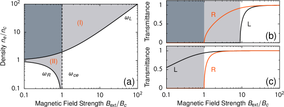
We focus on the transmittance of the R and L waves at the interface between the vacuum and a plasma target. Since the electromagnetic waves can propagate in plasmas only when is positive in the linear amplitude limit. Figure 1 indicates the propagation features along a magnetic field summarized in the density and magnetic field diagram ( vs. ), which is the so-called CMA (Clemmow-Mullaly-Allis) diagram Stix (1992). Here, the cold plasma approximation is adopted, and the ion mass is assumed to be much higher than the electron mass. The parameter space is divided into several regions by the cutoff conditions for the R and L waves ( and ) and the cyclotron resonance condition (), where the cutoff frequency for each wave is written as
| (3) | |||
| (4) |
This diversity in the propagation features is quite different from the normal cutoff condition ( or ) without the external magnetic field.
The forbidden regions for the R and L wave are different. An LP light is regarded as a combined wave of a right-hand CP (RCP) and a left-hand CP (LCP) wave. If one of the CP waves is allowed to enter the plasma target, but the other is forbidden, the plasma target will work as a filter to generate a CP wave from an LP light. Two regions satisfy such conditions, which are labeled by (I) and (II) in Fig. 1(a).
When the magnetic field strength is larger than the critical , the whistler-wave mode of the R wave propagates in plasmas at any density. On the other hand, there is a cutoff density for the L-wave component. Only the R wave is allowed to pass through the plasma target in the region (I). Since the L-cutoff density depends on the field strength as , the parameter range of the region (I) is given by
| (5) |
The transmittance of the R and L wave at the vacuum-plasma boundary is evaluated by the refractive indexes according to the Fresnel formula Budden (1961). The energy fraction of the transmitted wave relative to the injected energy of each CP wave is derived as , where the subscript denotes or . The reflectivity is then .
Figure 1(b) shows the transmittance and for a plasma density with . The region (I) corresponds that for this case, which is highlighted by light-gray in the figure. The most ideal situation for the R-wave generation is and . In the region (I), the L wave is perfectly reflected, whereas the transmittance for the R wave increases with the magnetic field strength. Then the highest transmittance for the whistler wave will be realized at just below the L-cutoff, that is . This magnetic field strength is the optimized condition by which the plasma foil target will work as an R-wave filter most efficiently. The higher transmittance could be realized for much denser targets as well, although the optimal strength of the magnetic field becomes larger .
By contrast, only the L wave is allowed to propagate in the region (II) of Fig. 1(a). The parameter range of the region (II) can be expressed as
| (6) |
The required strength of the magnetic field is much smaller compared to that of the region (I), which could be an advantage in terms of practical application. The transmittance for the case of is depicted in Fig. 1(c). The region (II) for this case is the range of . The transmittance of the L wave increases with , whereas the R wave starts to enter the plasma when . Then the best performance as an L-wave filter ( and ) will be achieved at just below the resonance condition, that is . Because of the lower density of the region (II), the relativistic effects may not be ignored when the incident laser amplitude is relativistic (see more Sec. V).
By controlling such propagation properties, we can design a plasma device that converts an LP light into CP waves. In this paper, we concentrate our discussion on the region (I) where only the whistler wave gets into the plasma. In the following, we will search for the optimal conditions of the plasma photonic device to generate CP lights with the help of multi-dimensional PIC simulations.
III Numerical Setup
The interaction between a short-pulse laser and a dense plasma foil is examined in our numerical experiment. We consider a simple situation in which a thin foil target of solid hydrogen is irradiated by a Gaussian-shape laser. The plasma target is assumed to be fully ionized initially. The number densities of the electrons and ions, , are spatially constant inside the target. For simplicity, the foil is in contact directly with the vacuum without any preplasma. The thickness of the target is set to be the same as the laser wavelength in the vacuum. Hereafter the length scale is normalized by the laser wavelength such as .
The injected laser is an LP light traveling in the direction. The pulse duration at half maximum amplitude is , where the unit of time scale is given by the laser period and is the speed of light. The incident angle of the laser is normal to the target surface, and the focal spot is in diameter. The peak laser intensity is parameterized by the normalized vector potential via the relation of , where is the laser electric field and is the vacuum permittivity. A uniform external magnetic field is applied parallel to the laser propagation direction.
Numerical simulations on the laser-plasma interaction in Cartesian coordinates (, ) are calculated by a PIC scheme, PICLS Sentoku and Kemp (2008). The collision term is ignored in this analysis, unless otherwise mentioned. The computational domain is set to be , and the plasma target is located at the middle . The escape boundary conditions for the electromagnetic waves and plasma particles are applied at both side of the boundaries, whereas the periodic boundary conditions are adopted in the direction. The spatial and time resolutions are and the particle number is 100 per each grid at the beginning. The third order interpolation algorithm is used to suppress the numerical heating. The time resolution should be sufficiently smaller than the electron gyration time as well as the plasma oscillation time to avoid the unphysical numerical heating in strongly magnetized plasmas.
The transmittance and reflectivity of the electromagnetic waves are assessed by integrating the energy of the waves passing through each side of the boundary. The calculations are continued long enough until the transmittance and reflectivity become constant with time, which is typically after the injected laser hits the target. The key parameters of this system are the target density , the magnetic field strength , and the laser amplitude . The fiducial values representing the region (I) are selected as , , and . The dimensional quantities of these fiducial parameters are estimated as a function of the laser wavelength . For instance, the laser intensity is given by W/cm2, where is the laser wavelength in microns. The critical density is calculated as m-3, and the critical magnetic field strength is kT. For this case, the unit time corresponds to fs.
IV Numerical Results
The transmittance and reflectivity of the injected LP laser light are evaluated by 2D PIC simulations. In this section, the density of the plasma target is fixed to be , and then we will seek conditions that only the whistler wave is selectively transmitted. The foil thickness is , and the amplitude and pulse duration of the laser are = 1 and . After enough time has passed since the laser-plasma interaction, the incident laser energy should be transferred to four different forms: the transmitted and reflected electromagnetic-wave energies and the absorbed ion and electron kinetic energies.
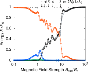
The outcome of the energy redistribution after the laser-plasma interaction depends on the strength of the external magnetic field. The transmittance and reflectivity in terms of the incident laser energy are depicted by the black and red circles in Fig. 2. The final state of the ion and electron kinetic energies are also shown by the green and blue circles, respectively. The energy conversion to plasmas is not significant except for the cases around , where the electrons absorb the wave energy through the cyclotron resonance Sano et al. (2017). Then, most of the laser energy remains in the form of electromagnetic waves.
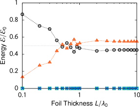
The numerically obtained transmittance is consistent with the theoretical estimation shown by the gray dashed curve in Fig. 2. Because an LP light is a sum of an RCP light and an LCP light, each having a half component, the total transmittance at a given is basically the average of and shown in Fig. 1(b). Note that the effect of multiple reflections on both sides of the target surface is taken into account in the theoretical curve. The numerical results of the transmittance seem to oscillate around the predicted curve in the range of . The oscillation is due to the interference by multiple reflections inside the target. The oscillation peaks in the transmittance appear when an integer multiple of the whistler wavelength () coincides with the optical path difference of (see the labels at the top of Fig. 2). When the target thickness becomes much thicker than the whistler wavelength (e.g., ), the oscillatory behavior disappears, and the numerical results exhibit an excellent agreement with the theory. If the target is sufficiently thicker than the electron skin depth , the transmittance feature is independent of (see Fig. 3).
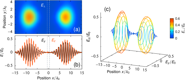
In this analysis, we look for the physical parameters of a plasma device that is transparent for the R wave and entirely reflective for the L wave. It is confirmed that the ideal situation as for a CP wave generator is realized when the magnetic field strength is just below the L-cutoff condition, that is . Figure 4 shows snapshot images of the electromagnetic waves in one of the best parameters as the plasma device. The field strength of this run is .
The spatial distribution of the perpendicular component of the electric field is indicated in Fig. 4(a). The target foil is located at the center, and the incident laser comes from the left. The energy conversion efficiency from the injected LP light to the transmitted wave is 0.47. At the time of the snapshot, the transmitted wave and the reflected wave exist almost symmetrically to the target. Figure 4(b) is a 1D distribution of the electric field along the -axis. The phase delay of between and indicates that the transmitted wave is the R wave and the reflected wave is the L wave. The amplitude of the transmitted and reflected wave is about half of the incident laser amplitude, . The polarization is mostly circular, but slightly elliptical. For example, the deviation of the amplitude between and is around 20% in the transmitted wave, which might be due to the contamination of components other than the whistler-wave mode. Figure 4(c) is a 3D plot of the direction of the vector shown in Fig. 4(b). It is evident that two CP waves are generated successfully after the laser-plasma interaction.
Note that both of the transmitted and reflected CP waves are RCP waves with respect to the propagation direction. The magnetic field direction is parallel to the laser injection. The transmitted wave is the R wave so that the circular polarization is right-hand to the propagation direction. The reflected wave, on the other hand, is the L wave, and then it has left-hand polarity to the magnetic field direction. Because the propagation direction is opposite to the magnetic field, the reflected wave is also right-hand to the propagation direction. Then, this plasma device generates two RCP waves propagating in the opposite direction. It might be possible to establish an optics system for combining these two CP lasers in practical experiments.
Interestingly, if the magnetic field direction is anti-parallel to the laser propagation (i.e., ), two LCP waves will be formed by the same process. Therefore, the polarity of the generated CP waves can be selected by the direction of the external magnetic field.
The laser-plasma interaction considered here is independent of the spatial dimensions of the simulations. In Fig. 2, the 1D and 3D PIC results are plotted by the solid curves and cross marks, respectively. As seen from the figure, all the data exhibit the same trend, and which indicates that the effect of the finite laser spot must be negligible. The numerical resolution of the 1D runs is identical to that of the 2D simulations. The conclusions illustrated by Fig. 2 are unaffected by the numerical resolutions, which has been tested by the higher resolution runs in 1D with . It is also verified by 1D runs that the inclusion of the collisional effects has little influence on the transmittance in our system. The fiducial run is also performed in 3D, where the grid resolution is and fewer particle numbers (20 per grid) are solved. These numerical results demonstrate that the discovered feature of this plasma device is robust and quite practical.
The most significant advantage of this plasma device is that it is applicable even for the relativistic amplitude of the wave. If the amplitude of the injected wave is relativistic, the transmitted wave amplitude could also be nearly relativistic. Figure 5 denotes the dependence of the transmittance on the laser amplitude . The fiducial parameters, and , are adopted for these 2D simulations. When , some particles have escaped from the computational domain, but those are not counted in the energies of this figure. The escaped energy is at most 10% of the injected laser energy.
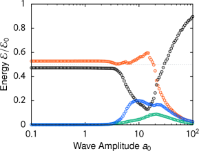
The transmittance is independent of the laser intensity until . The polarization property of the transmitted wave is also unchanged for this range of . These facts confirm the applicability of this mechanism in the relativistic intensity regime. It should be noticed that even when the amplitude of the transmitted whistler wave is relativistic, , the electron quiver velocity remains still non-relativistic, . It is because the magnetic field considered here is sufficiently large enough.
If the laser amplitude becomes further higher, there are two relativistic effects that prevent the CP wave generation. One is the electron heating through the cyclotron resonance. The external magnetic field in these runs is far beyond the resonance condition. However, due to the relativistic correction, the resonance condition becomes , where is the Lorentz factor of electrons. The electrons in the target gain the energy efficiently through the resonance when Sano et al. (2017). In fact, the electromagnetic energy entered into the target is largely absorbed by the electrons, and the transmittance decreases drastically in the range of .
The sudden rise in the transmittance at is caused by the other effect, that is the relativistic transparency Kaw and Dawson (1970); Sakagami and Mima (1996). The cutoff density for the relativistic-amplitude laser is approximately given by . The minimum intensity for the relativistic transparency is obtained by , where the quiver energy is assumed. This is also consistent with the numerical results shown in Fig. 5. Therefore, the maximum intensity valid for the CP wave generator could be managed by the field strength and the target density.
V Discussion
For practical use of this plasma photonic device, it might be difficult to align the magnetic field direction precisely the same as the laser direction. Then, it would be important to examine the angle dependence of the transmittance. The laser injection is kept to be along the -axis in the following analysis. We define as an angle between the laser and magnetic field directions in the unit of degree. Here the angle is assumed to vary within the - plane. The angle (0) denotes that the magnetic field direction is along the -axis (-axis).
2D PIC simulations reveal the angle dependence of the efficiency of our plasma device. The angle dependence of the phase velocity in the region (I) is characterized by a figure-eight shape of the wave normal surface Stix (1992). Thus, the transmittance of the R-wave branch should have a dependence on the angle . The polarization angle of the incident LP wave is another independent parameter, so that we examine two cases, and . In the former cases, the electric field of the incident laser has a parallel component to the external magnetic field. However, the laser electric field is always perpendicular to in the latter cases.
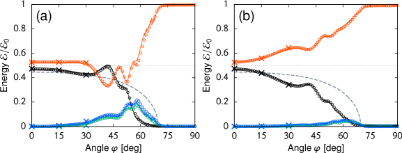
Figures 6(a) and 6(b) show the angle dependence of the energy redistribution for the cases that the initial electric field is parallel to the -axis and -axis, respectively. Except for the angle , the model parameters are identical to the fiducial run shown by Fig. 4, in which the plasma density is , the magnetic field strength is , and the incident laser amplitude is . The fiducial run corresponds to the angle case.
It is found that the transmittance feature is roughly independent of the angle when the angle is less than about 15 degrees. These results suggest the angle tolerance for the installation of this plasma device. The transmittance of the R-wave branch decreases with the increase of the angle. When the angle is , the injected wave is totally reflected. As a reference, the theoretical curve is indicated by the gray dashed curve in Fig. 6, which corresponds to half of the transmittance for the R-wave branch. There is a critical angle where the transmittance, or the phase velocity of the electromagnetic wave, becomes zero Stix (1992). When the electric field has the component [Fig. 6(a)], a fairly large amount of the plasma heating occurs near the critical angle . The parallel component of the electric field in terms of the external magnetic field is essential for the resonant absorption by electrons for this case. The 1D and 3D PIC results in Fig. 6 make sure that the angle dependence is unaffected by the spatial dimensions of the simulations.
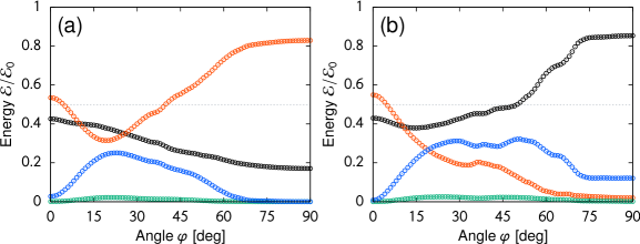
In Sec. IV, the transmittance of the R wave is examined intensively. However, as discussed in Sec. II, the extraction of only the L wave may also be possible in the parameter region (II). A benefit of the L-wave filter is that the required strength of the magnetic field is relatively smaller, so that it could be more feasible for practical use. On the other hand, a defect of the L wave extraction is a weaker limit in the laser intensity. Because of the relativistic transparency, the cases of are inappropriate for the LCP wave generation by our method. Furthermore, it turned out that there is a severe angle dependence in the transmittance of the L wave. The ideal transmittance of the L wave is realized only when the laser injection is strictly parallel to the external magnetic field. Otherwise, a large fraction of the laser energy goes to the thermal energy of electrons.
Figure 7 shows the angle dependence of the energy fraction after the laser-plasma interaction for a typical case in the region (II). The model parameters calculated here is the plasma density , the magnetic field strength , and the incident laser amplitude . The other parameters are the same as in Fig. 6. When the laser injection is parallel to the magnetic field (), both of the transmittance and reflectivity are nearly half of the injected energy. In this case, only the L-wave component is transparent, and thus it works as a converter to LCP waves from an LP laser. However, if the angle is not zero, the energy absorption by the electrons cannot be ignored. If underdense preplasmas form at the ablation side of the target, the electrons are accelerated effectively by the laser field through the force. The wave propagation is allowed at any angle for this case, which is the L wave at and the X wave at . The angle dependence of the transmittance and reflectivity exhibits complicated behavior, as seen in Figs. 7(a) and 7(b).
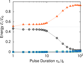
In this paper, the incident angle of the laser is assumed to be always normal to the target surface. Even when the laser has an incident angle to the target, if the magnetic field is parallel to the laser direction, the transmitted light should have circular polarization. It might be interesting to investigate the dependence of the transmittance on the laser incident angle together with the dependence. We ignore the effects of preplasmas in this analysis, because the preplasma has little influence on the propagation of the whistler wave. Throughout this analysis, we assume a relatively shorter pulse duration for the injected laser, . However, the stimulated Brillouin scattering could prevent whistler-wave propagation if the pulse duration becomes longer (see Fig. 8). The critical pulse length is determined by the growth time of the Brillouin instability, and thus it would depend largely on the laser intensity Sano et al. (2020). The dependence of the transmittance on the pulse duration would also be an exciting task to be studied.
VI Conclusions
We have investigated a unique mechanism of CP wave generation by controlling the laser-plasma interaction under a strong magnetic field. When a thin plasma foil is irradiated by an LP laser under some appropriate conditions, the transmitted and reflected lights become circularly polarized and have nearly the same intensity. The whistler-mode of the R wave passes through a thin plasma target when , while the L-wave component is totally reflected. To function as a conversion filter, the density of the plasma foil should be higher than . The optimal condition requires a strong external magnetic field with a size of along the incident light direction. The polarity of the CP waves can be switched by the direction of the magnetic field. The transmittance is unaffected by a small angle difference between the wave injection and the magnetic field less than about 15 degrees.
A significant result of this work is that linear analysis of this problem is quite adequate for assessing the behavior of this concept even for the relativistic laser intensity. The advantage of this plasma photonic device is a large amplitude of CP wave, which is valid even for the relativistic amplitude. Therefore, the high-intensity CP waves generated by this plasma device could be useful for high-energy-density plasma experiments, such as laser-driven ion acceleration Esirkepov et al. (2004); Fiuza et al. (2012) and ion heating in overdense plasmas Sano et al. (2019, 2020). It would be possible to propose plasma photonic devices for various different uses by appropriately selecting the plasma environment for the density and magnetic field strength. In the future, it will be meaningful to pursue further device developments for ultra-intense lasers while utilizing numerical simulations.
Acknowledgements.
We thank Ryosuke Kodama, Kunioki Mima, and Yoshitaka Mori for useful discussions. This research was partially supported by JSPS KAKENHI Grant No. JP19KK0072, JP20H00140, and JSPS Core-to-Core Program, B. Asia-Africa Science Platforms No. JPJSCCB20190003.References
- Kodama et al. (2004) R. Kodama, Y. Sentoku, Z. L. Chen, G. R. Kumar, S. P. Hatchett, Y. Toyama, T. E. Cowan, R. R. Freeman, J. Fuchs, Y. Izawa, M. H. Key, Y. Kitagawa, K. Kondo, T. Matsuoka, H. Nakamura, M. Nakatsutsumi, P. A. Norreys, T. Norimatsu, R. A. Snavely, R. B. Stephens, M. Tampo, K. A. Tanaka, and T. Yabuuchi, Nature 432, 1005 (2004).
- Kapteyn et al. (1991) H. C. Kapteyn, A. Szoke, R. W. Falcone, and M. M. Murnane, Opt. Lett. 16, 490 (1991).
- Michel et al. (2009) P. Michel, L. Divol, E. A. Williams, S. Weber, C. A. Thomas, D. A. Callahan, S. W. Haan, J. D. Salmonson, S. Dixit, D. E. Hinkel, M. J. Edwards, B. J. MacGowan, J. D. Lindl, S. H. Glenzer, and L. J. Suter, Phys. Rev. Lett. 102, 025004 (2009).
- Moody et al. (2012) J. D. Moody, P. Michel, L. Divol, R. L. Berger, E. Bond, D. K. Bradley, D. A. Callahan, E. L. Dewald, S. Dixit, M. J. Edwards, S. Glenn, A. Hamza, C. Haynam, D. E. Hinkel, N. Izumi, O. Jones, J. D. Kilkenny, R. K. Kirkwood, J. L. Kline, W. L. Kruer, G. A. Kyrala, O. L. Landen, S. LePape, J. D. Lindl, B. J. MacGowan, N. B. Meezan, A. Nikroo, M. D. Rosen, M. B. Schneider, D. J. Strozzi, L. J. Suter, C. A. Thomas, R. P. J. Town, K. Widmann, E. A. Williams, L. J. Atherton, S. H. Glenzer, and E. I. Moses, Nat. Phys. 8, 344 (2012).
- Malkin et al. (1999) V. M. Malkin, G. Shvets, and N. J. Fisch, Phys.l Rev. Lett. 82, 4448 (1999).
- Shi et al. (2017) Y. Shi, H. Qin, and N. J. Fisch, Phys. Rev. E 95, 023211 (2017).
- Carman et al. (1981) R. L. Carman, D. W. Forslund, and J. M. Kindel, Phys. Rev. Lett. 46, 29 (1981).
- Esirkepov et al. (2004) T. Esirkepov, M. Borghesi, S. V. Bulanov, G. Mourou, and T. Tajima, Phys. Rev. Lett. 92, 175003 (2004).
- Fiuza et al. (2012) F. Fiuza, A. Stockem, E. Boella, R. A. Fonseca, L. O. Silva, D. Haberberger, S. Tochitsky, C. Gong, W. B. Mori, and C. Joshi, Phys. Rev. Lett. 109, 215001 (2012).
- Sano et al. (2019) T. Sano, M. Hata, D. Kawahito, K. Mima, and Y. Sentoku, Phys. Rev. E 100, 053205 (2019).
- Sano et al. (2020) T. Sano, S. Fujioka, Y. Mori, K. Mima, and Y. Sentoku, Phys. Rev. E 101, 013206 (2020).
- Michel et al. (2014) P. Michel, L. Divol, D. Turnbull, and J. D. Moody, Phys. Rev. Lett. 113, 205001 (2014).
- Michel et al. (2020) P. Michel, E. Kur, M. Lazarow, T. Chapman, L. Divol, and J. S. Wurtele, Phys. Rev. X 10, 021039 (2020).
- Lehmann and Spatschek (2016) G. Lehmann and K. H. Spatschek, Phys. Rev. Lett. 116, 225002 (2016).
- Lehmann and Spatschek (2018) G. Lehmann and K. H. Spatschek, Phys. Rev. E 97, 063201 (2018).
- Stark et al. (2015) D. J. Stark, C. Bhattacharjee, A. V. Arefiev, T. Toncian, R. D. Hazeltine, and S. M. Mahajan, Phys. Rev. Lett. 115, 025002 (2015), 1412.1865 .
- Fujioka et al. (2013) S. Fujioka, Z. Zhang, K. Ishihara, K. Shigemori, Y. Hironaka, T. Johzaki, A. Sunahara, N. Yamamoto, H. Nakashima, T. Watanabe, H. Shiraga, H. Nishimura, and H. Azechi, Sci. Rep. 3, 1170 (2013).
- Santos et al. (2018) J. J. Santos, M. Bailly-Grandvaux, M. Ehret, A. V. Arefiev, D. Batani, F. N. Beg, A. Calisti, S. Ferri, R. Florido, P. Forestier-Colleoni, S. Fujioka, M. A. Gigosos, L. Giuffrida, L. Gremillet, J. J. Honrubia, S. Kojima, P. Korneev, K. F. F. Law, J.-R. Marquès, A. Morace, C. Mossé, O. Peyrusse, S. Rose, M. Roth, S. Sakata, G. Schaumann, F. Suzuki-Vidal, V. T. Tikhonchuk, T. Toncian, N. Woolsey, and Z. Zhang, Phys. Plasmas 25, 056705 (2018).
- Budden (1961) K. G. Budden, Radio waves in the ionosphere (Cambridge University Press, New York, 1961).
- Yang et al. (2015) X. H. Yang, W. Yu, H. Xu, M. Y. Yu, Z. Y. Ge, B. B. Xu, H. B. Zhuo, Y. Y. Ma, F. Q. Shao, and M. Borghesi, Appl. Phys. Lett. 106, 224103 (2015).
- Luan et al. (2016) S. X. Luan, W. Yu, F. Y. Li, D. Wu, Z. M. Sheng, M. Y. Yu, and J. Zhang, Phys. Rev. E 94, 053207 (2016).
- Ma et al. (2016) G. Ma, W. Yu, M. Y. Yu, S. Luan, and D. Wu, Phys. Rev. E 93, 053209 (2016).
- Weng et al. (2017) S. Weng, Q. Zhao, Z. Sheng, W. Yu, S. Luan, M. Chen, L. Yu, M. Murakami, W. B. Mori, and J. Zhang, Optica 4, 1086 (2017).
- Stix (1992) T. H. Stix, Waves in plasmas (Springer-Verlag, New York, 1992).
- Sentoku and Kemp (2008) Y. Sentoku and A. J. Kemp, J. Comp. Phys. 227, 6846 (2008).
- Sano et al. (2017) T. Sano, Y. Tanaka, N. Iwata, M. Hata, K. Mima, M. Murakami, and Y. Sentoku, Phys. Rev. E 96, 043209 (2017).
- Kaw and Dawson (1970) P. Kaw and J. Dawson, Phys. Fluids 13, 472 (1970).
- Sakagami and Mima (1996) H. Sakagami and K. Mima, Phys. Rev. E 54, 1870 (1996).