Designing drones by combining finite element and atomistic simulations: a didactic approach
Abstract
A didactic multiscale approach for drone modeling is proposed. Specifically, we investigate the drone structure at both macroscopic and microscopic scales, by making use of finite element and atomistic simulations, respectively. The structural analysis is performed with the aim to equip the drone with specific sensors and measuring instruments capable to detect the existence of volcanic ash, SO2, CO2 and other pollutants in the atmosphere after a vulcanic eruption. We show that, by modeling the tubular structure of the drone with a sandwich constituted by a a polystyrene core, carbon fiber skins and epoxy matrix, a weight saving of 7 grams for each drone arm can be obtained, in comparison to the standard commercial drones, although a slight worsening of the mechanical performances is observed. In addition, the molecular structure of the polystyrene chains has been investigated by using atomistic Molecular Dynamics simulations, providing further information on the local structure of the polymer chains. Additional improvements of the weight saving could be obtained by means of the the topological optimization techniques on the body of the drone and on the supports for landing.
I Introduction
The mechanical design of lightweight structures allows to obtain, through a
topological and material optimization, a lighter and more efficient
structure Sigmund:13 , capable of maintaining the same mechanical
performances as the native material, and in some cases improving them.
In the course of the last fifty years, composite materials such as carbon
fiber or kevlar have supplanted the use of metals as aluminum in the creation
of cockpits in various competitive sports as well as in the automotive
and offshore sectors Cucinotta:20 .
Over the past decade, many steps forward have been made
in additive manufacturing
(AM) Gardan:16 and thanks to topological optimization
techniques, it is possible to produced lightweight structures
quickly and efficiently Cucinotta:19 .
A widespread application of such a technology is constituted by drones, which
can be used in a large variety of context, from simple entertainment to the
monitoring of meteorological conditions and atmospheric pollutants.
For instance, it is possible to equip drones with proper sensors capable
of measuring the quantity of polluting gases in the upper atmosphere.
One of the building blocks constituting drones that requires a great care
during the assembly phase is the frame. Indeed, the latter must be capable to
withstand the large amount of stress to which the drone is usually subjected
during the flight phase. The frame of a drone typically consists of a support
constitued by plastic material, aluminum and carbon.
The behavior of plastic material, in particular, is crucial in order to
provide the necessary flexibility to the frame; at the same time, this
material must be strong enough to avoid breakages and also has to act as a
thermic and electrical insulator.
In the present work we didactically explain how is possible to model a drone
with the desired properties by making use of the finite elements simulations.
The proposed study is motivated by the possibility to use such a drone to
measure the amount of volcanic ash, SO2 and CO2 released in the atmosphere
during a volcanic eruption. In addition, the drone can also be used as an
efficient tool to provide early warning on the volcanic activity.
The possibility to perform these measurements
would constitute a strong validation of numerical models, such as the
Weather Research and Forecasting model coupled with chemistry
(WRF-Chem) Grell:05 ; Stuefer:13 ,
specifically developed to monitor the existence of pollutants in the
atmosphere. The WRF-Chem package is the generalization of the meteorological
WRF model Skamarock:08 ; Powers:17 , suited to investigate, among others,
convective motions Castorina:19 ,
nucleation processes Restuccia:18
and heavy rainfall events MTCaccamo:17 ; further atmospheric phenomena can
be modeled by using theoretical approaches, such as those based on adiabatic
expansion and compression MTCaccamo:19 ; Castorina:18 .
In addition, we also show how to investigate the microscopic behavior
of the plastic materials constituting the drone frame by using Molecular
Dynamics (MD) simulations which, along with experimental techniques like
X-ray scattering, has been largely used to investigate the fluid structure
of polymers and block copolymers Lombardo:19 .
Therefore, upon combining these two different methods,
we propose a simple approach to a multiscale modeling of drones.
Specifically, the MD-based investigation is focused on
the polystyrene,
a remarkable example of plastic material whose properties can be
succesfully detailed by using computer simulations.
In this context, the
MD technique has been largely adopted to perform simulation studies
of both polystyrene melts Harmandaris:11 ; Denicola:16
and composite materials obtained by filling the
polymer matrix with inorganic
particles Muller-Plathe:12 ; Ndoro:11 ; Munao:18a ; Munao:19 or
nanotubes Zhao:16 ; Donati:20 .
The employment of the MD techniques allows to gain
knowledge into the structural and dynamical properties of polymer chains,
which, in turn, determine the final properties of the material. In particular,
it is possible to estimate the chain relaxation, i.e. the time required
by a polymer chain to assume its equilibrium configuration, which strictly
depends on temperature, density and interactions with other chains and with
the solvent. In addition, the computation of the end-to-end distance,
gyration radius, chain orientation and density profiles allows to obtain
a general picture of the miscroscopic properties of the
material Munao:18a ; Sparnacci:20 .
As far as the finite elements simulations are concerned,
the case study investigated in the present work
is that of a commercial drone model DJI S900 for which we show
how to make the supporting structure lighter, at the same time leaving the
mechanical characteristics unchanged. This will allow for a greater battery
autonomy which translates into longer flight time.
The finite element software used in this work is the Siemens Nx Nastran.
The didactic approach proposed in this work, based on the
“learning by doing” method, is presented in the next section.
The design of the drone structure is described in Section III, while
details on the computational approaches
suited to investigate the structural properties of
polystyrene chains are given in Section IV. The finite element simulations
are presented and discussed in Section V, and finally conclusions
follow in the last section.
II Didactic methodology: learning by doing
The didactic approach proposed in the present manuscript can be fruitfully addressed through the “learning by doing” method. The learner is not a simple, passive, observer, but actively participates to the realization of the project target, at the same time learning the mechanisms behind it. Specifically, he will have to start designing the drone structure by following the prescriptions of finite element simulations. Also, he will have the possibility to learn the basis of Molecular Dynamics simulations. The required prerequisites are a basic knowledge of atomic and molecular chemistry, along with the knowledge of mechanics and statics of rigid bodies. Starting from these basis, the learner will have the possibility to design the system to be investigated; for instance, as detailed in Section IV, he will have to built a simulation box containing a certain number of polystyrene chains. Starting from different possible configurations, he could decide, for instance, to put many polymer chains of low molecular weight or rather few chains with high molecular weight: even if the total number of atoms is the same, the simulations could provide different results. In this way the learner will be able to infer which is the best compromise between speed calculation and model accuracy. A good combination of these two aspects is reported in Section IV. A similar approach holds for the finite element simulations, where the learner, upon modeling the tubular structure of the drone with a polystyrene matrix, will obtain a weight saving at the expense of mechanical properties. According to this didactic approach, the main target is not to memorize the procedure, bur rather to understand the whole mechanism, enabling the learner to face new problems.
III The drone structure
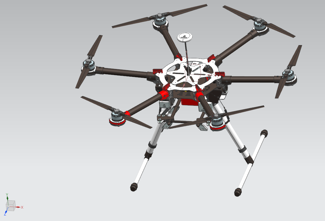
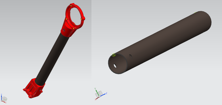
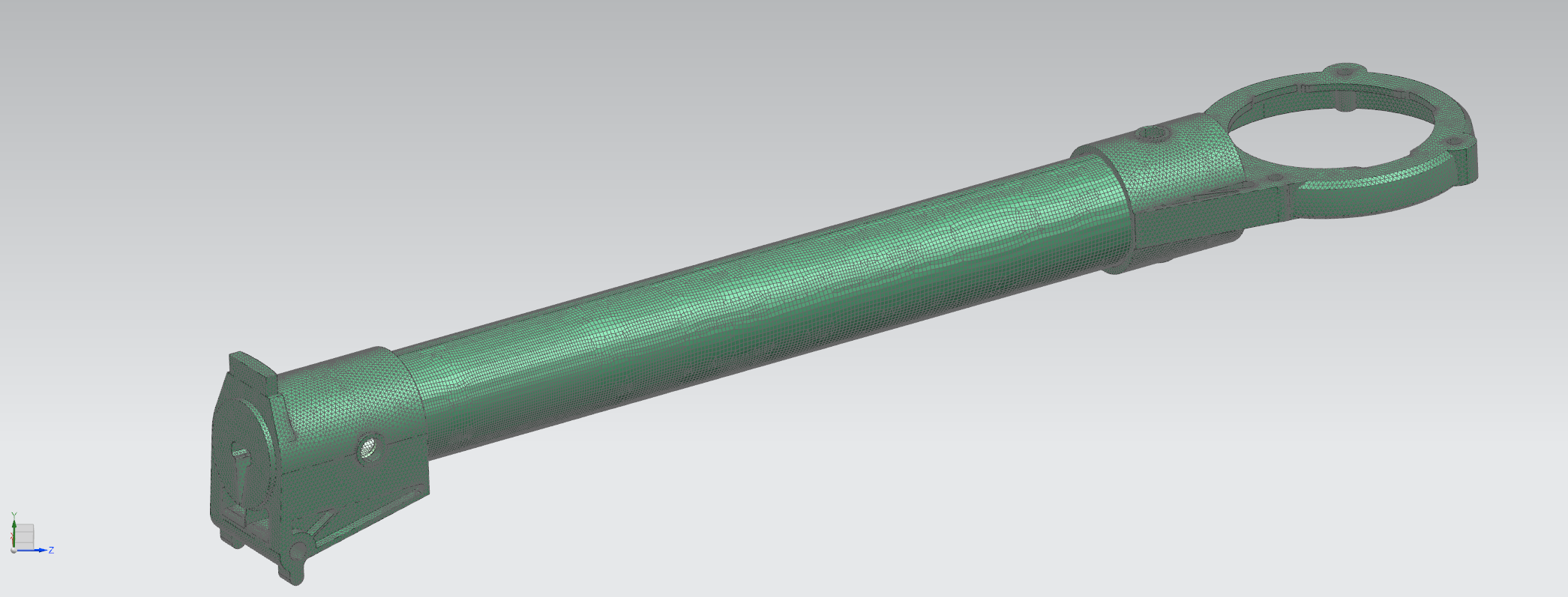
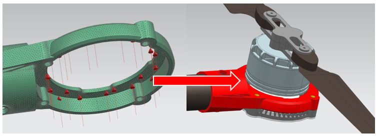
In the present work we simulate the realization of a drone after the replacement of the laminate of the supporting structure of the rotors (made up of only carbon fiber and epoxy resin) with a sandwich consisting of a polystyrene core (center) and a skin made of carbon fiber and epoxy resin; the two laminates will be compared both as regards the weight and the mechanical performances obtained. The use of polystyrene has already been studied either as the core of a sandwich or doped with other elements such as carbon nanotubes Qian:00 ; Teodorescu:08 ; Potter:17 . The drone considered in this work is the marketed DJI S900, a hexacopter with six arms that support the six rotors. The main features include a maximum motor power of 500 watts, a total weight (including batteries) of 3.3 Kg and a takeoff weight of 8 Kg. The tubular laminate of the drone arm (with a thickness of 1 mm) is realized in carbon fiber; the rotor fixing and arm anchoring to the body of the drone is made in aluminum; the drone body for electronic control housing is constituted by plastic materials. The reverse engineering of the drone is reported in Fig. 1. The aim of the present study is to analyze the drone performaces upon replacing the epoxy matrix of the rotor bearing structure with a polystyrene matrix. The rotor bearing structure is formed by a tube with a thickness of 1 mm. In Fig. 2 it is possible to observe the Computer-Aided Design (CAD) of one of the arms studied in this work: the red components are made in aluminum, while the tubular part is a laminate in carbon fiber.
The mechanical characteristics of the materials used for simulating the drone realization are reported in Tab. 1. In particular, we show the values of densities (in g/cm3), Young modulus E (in GPa), Poisson coefficient and yield stress (in MPa) of fiber carbon, epoxy, polystyrene and aluminum. The Poisson coefficient is defined as the ratio between transverse and longitudinal deformation, therefore is adimensional.
| [g/cm3] | E [GPa] | [MPa] | |||
|---|---|---|---|---|---|
| Fiber carbon | 1.8 | 240 | 0.2 | 4500 | |
| Epoxy | 1.3 | 3 | 0.37 | 27 | |
| Polystyrene | 1.01 | 3.5 | 0.45 | 30 | |
| Aluminum 6061 | 2.71 | 69 | 0.33 | 276 |
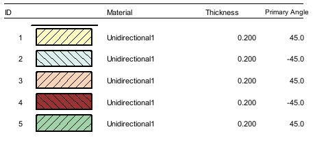
The structure of the laminate (top panel of Fig. 3) consists of five layers with the orientation of the fibers at +/- and with a thickness of 0.2 mm for each layer.
 |
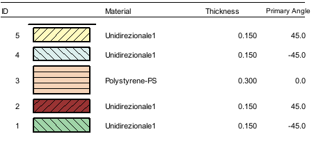 |
In the bottom panel of Fig. 3 it is shown the lamination plane of the sandwich. This is formed by a central core of polystyrene with a thickness of 0.3 mm and by two leathers placed both in the upper and lower part with fibers oriented to +/- 45∘ and thickness 0.15 mm. The NX Nastran software has a practical built-in tool that allows to create the laminate. We start by defining the datasheets of the materials constituting the composite, followed by the matrix, the reinforcement fiber and the volumetric fraction, defined as the ratio between the volume of the fibers (or matrix) and the total volume of the composite. In the laminate investigated in the present work the volumetric fraction of the matrix has been set to and for the fibers to . After defining the materials used, we move on to the mesh phase, whose main feature is to discretize the continuous body in a grid made up of elements of various shapes (triangles, quadrilaterals for 2D domains or tetrahedrals for 3D mesh) connected together through points called nodes. This is done because in the calculation of the mechanical performance of a body, the calculator does nothing but apply the laws of classical mechanics ( differential equations) to nodes. This procedure is necessary, since, upon applying them to a continuous body, we would obtain infinite results; conversely, by properly discretizing the matter with a mesh, the mechanical behavior of the body can be approximated as close as possible to the real one, obtaining an advantage in the calculation speed. The denser the mesh (therefore the elements between the nodes are very small) the more precise the calculation will be at the expense of computational resources and computation time. As a consequence, a balance must be found between the mesh size and the computation time. In this work, the body was discretized with elements with a tetrahedral shape for the aluminum parts, while for the laminate quad elements were used and a size equal to 1 mm was set (see Fig. 4).
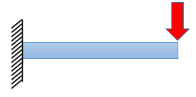
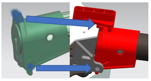
The boundary conditions of the system are two: the joint that holds the arm in the right position and the rotor that generates the lift force for pushing the drone upwards. The equivalent system is nothing more than a beam stuck on one side while the force is applied on the opposite side, as schematicaly shown in the left panel of Fig. 5.
|
|
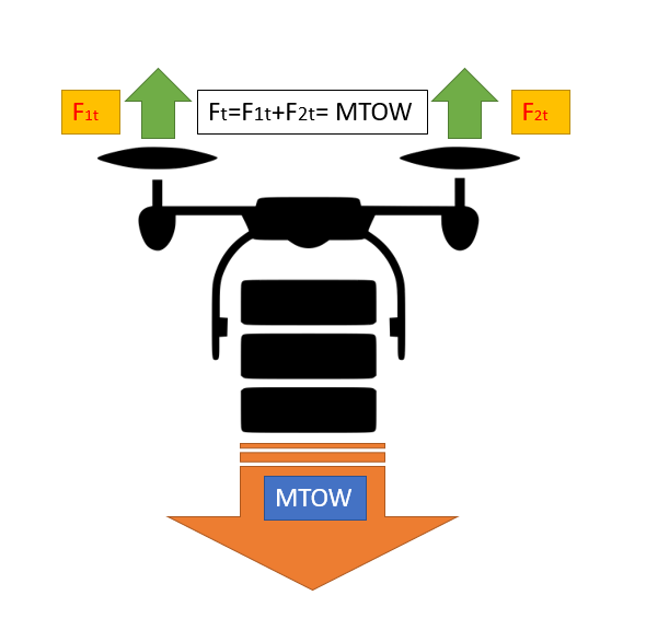
The joint is shown in the right panel of Fig. 5 and the drone arm remains in position thanks to a bottom hinge and a top stop colored in blue; this type of constraint blocks each of the six available degrees of freedom for each body. As regards the boost exerted by the six rotors, an important datum is given by the maximum takeoff weight (MTOW), which indicates the maximum weight at which the drone is able to take off. This value depends on the limits of the structure or on the limits of the motors: therefore in our study we have considered the most stressed condition, corresponding to a weight of 8 kg. In order to sustain the flight, the drone must have rotors capable of generating a boost at least equal to or greater than the weight transported, as shown in the left panel of Fig. 6. Given the maximum takeoff weight, the corresponding force that must be overcame is therefore:
| (1) |
where is the gravity acceleration. This force value must be divided by the number of rotors, therefore for each arm that supports the rotor it must exist a force equal to 13 N (see right panel of Fig. 6); this in turn will stress the arm with a bending moment.
IV Atomistic simulations of the polystyrene melt
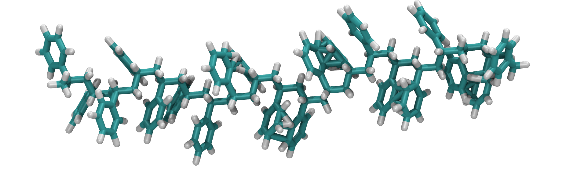
In the present section we briefly explain how to build a simplified model of the polystyrene melt by using the GROMACS Gromacs MD simulations. The whole procedure described herein is framed into a didactic approach and some specific details are missed in order to make the protocol as clear as possible. In this study we have investigated polystyrene chains constituted by 162 atoms, as reported in Fig. 7: specifically, a single polymer chain is constituted by 80 carbon atoms and 82 hydrogen atoms. The number of atoms is high enough to model a realistic polystyrene chains, but not so high as to become computationally expensive. Then, a cubic simulation box containing 68 polystyrene chains (and hence 11016 total atoms) has been built by using the Packmol program Packmol , which allows to randomly put the desired number of atoms and molecules inside a box with a given volume.
The box length has been fixed to 5 nm, in order to have a volume of 125 nm2 and therefore a polystyrene density of 950 kg/m2. Once built the initial configuration, we have made use of the OPLS force field Jorgensen:88 to set the intra and intermolecular potentials between the polystyrene chains. The bond distances between C and H atom, along with the numerical expression of bond stretching potential and the force constant are reported in Tab. 2. Here, and indicate the bond stretching and the equilibrium atomic distance, respectively.
| Bond | (nm) | kr(kJ mol-1 nm | |||
|---|---|---|---|---|---|
| C-C | 0.1380 | ||||
| C-H | 0.1070 |
| Atom | (nm) | (kJ mol | (e) | ||||
|---|---|---|---|---|---|---|---|
| C | 0.375000 | 0.439000 | 0.000 | ||||
| H | 0.235200 | 0.092000 | 0.000 |
In Tab. 3 we report all the non-bonded interactions, i.e. the interactions between atom pairs whose distance is not fixed by the connectivity. Specifically, in this table we have defined:
| (2) |
|
|
corresponding to the Lennard-Jones potential, which is calculated
through the interaction energy and the close-contact
distance . The chosen values for H atoms have been taken from
Ref. Munao:18 .
In principle, the total intermolecular potential is given by the sum of
the Lennard-Jones contribution and the Coulombic interaction.
However, in our simplified approch, the partial charges have been set to zero
everywhere, therefore this contribution does not influence the total
intermolecular potential.
In the present work all atomistic simulations have been performed in a
cubic simulation box with
periodic boundary conditions. The polymer melt has been simulated in a
canonical ensemble (NVT), in which temperature, volume and particle number have
been kept fixed. The temperature has been maintained contant at
by using the Nose-Hoover thermostat. This temperature has been chosen in order
to guarantee a fast relaxation of the polymer chains. According to the
simulation protocol followed in the present work, we first performed a
minimization procedure of 10 ps, with a time step of 1 fs, in order to
remove the possible atoms overlap. After this preliminary run, we have
performed an equilibration run of 30 ps, followed by a production run of
40 ps, where the final properties of the polymer melts have been calculated.
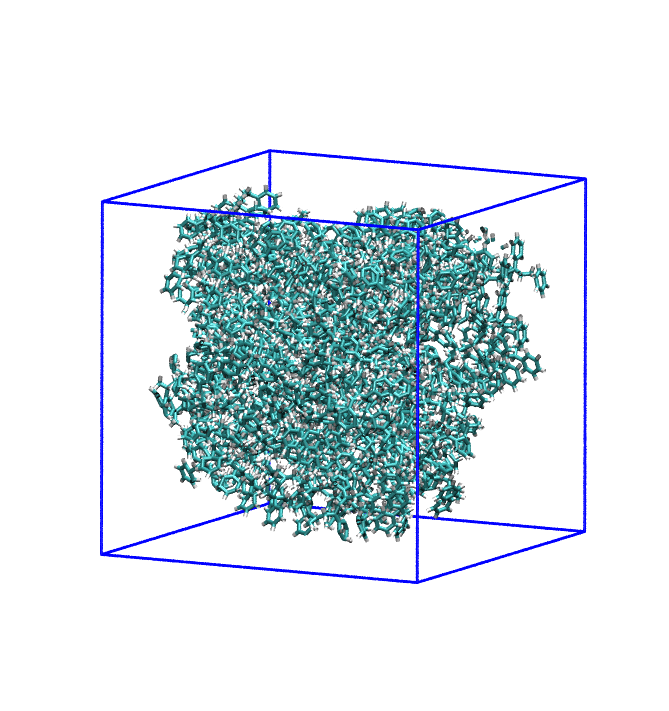
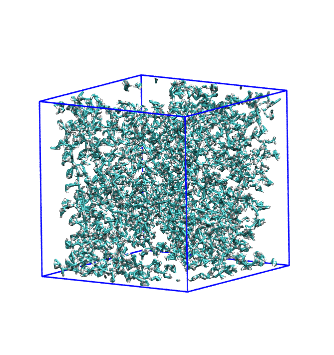
Two snapshots of the system at the beginning and at the end of the overall
simulation run are shown in Fig. 8.
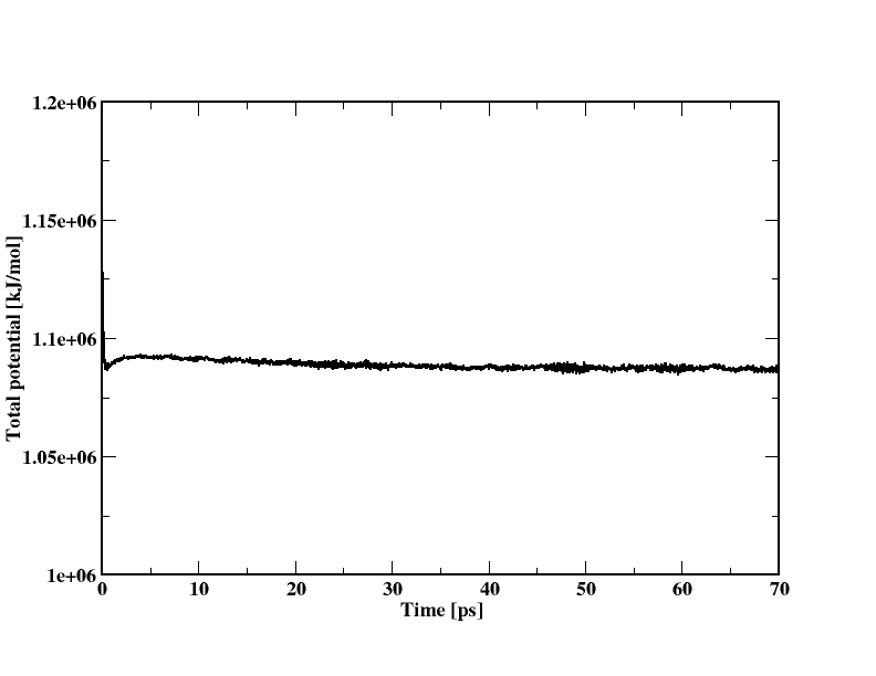
In order to ascertain whether the system reached the thermodynamic
equilibrium, it is possible to check the behavior of the total system energy
as a function of the simulation time. Indeed, the equilibrium occurs
when the energy does no longer chains with the time. In the left panel
of Fig. 9 the behavior of the system energy as a function of
the simulation time is reported: as visible, after a first decay, the energy
achieves a constant value of kJ/mol, after 30 ps.
Therefore, the properties of polystyrene chains have been calculated along the
next 40 ps, corresponding to the production stage.
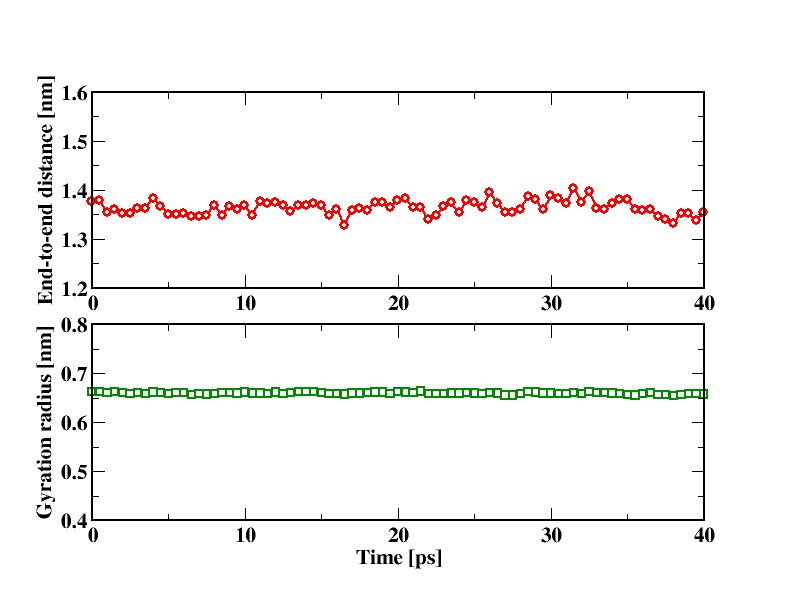
Once gained the thermodynamic equilibrium, many different
structural and thermodynamic properties of the system can be calculated.
As an example, we report
in the right panel of Fig. 9 the time dependence of the
end-to-end distance and the gyration radius of the polystyrene chains
investigated in this work. Their average values amount to 1.36 and 0.66 nm,
respectively. More detailed investigations, including the possible addition
of fillers inside the polymer matrix, are outside the scope of the present
work, but nonethless they can be performed, although more refined approaches
are required.
The multiscale approach presented in this work is then completed by
performing the finite element simulations, whose main results are reported
in the next section.
V Finite element simulations
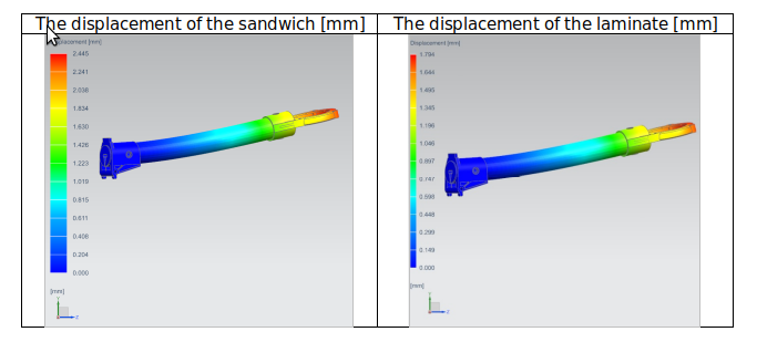
The finite element simulations have been performed through the Siemens Nx Nastran software and are divided into two steps. The first one is the preprocessing, where the mechanical properties of the material are set, including density, Young modulus of elasticity and yield stress. In this phase, the mesh is also created using the tool inside the software that allows the choice of the size of the element and its shape. The smaller the cell size of the element, the greater the calculation load of the calculator, and therefore the longer the processing time. The second phase concerns the applications of the boundary conditions, such as constraints, forces, contacts between bodies and application of frictions. Finally it is possible to choose the type of solution to adopt; some possible choices include linear, dynamic, non-linear static simulations, as well as the study of the ways of vibrating of a given structure. In this work we have chosen to use a linear static solution, which, for the software at issue, is called SOL 101. The displacement produced by the applied force is shown in Fig. 10; it is worth noting that the sandwich has lower mechanical performances than the laminate used on the commercial drone.
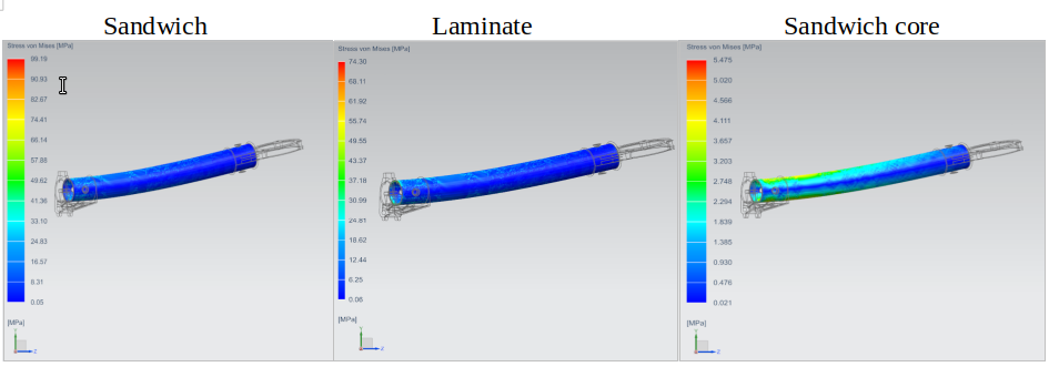
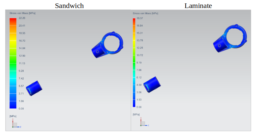
We have then computed the von Mises stress for sandwich and laminate, in order to predict the yielding of these materials under complex loading from the results of uniaxial tensile tests. Indeed, according to its definition, a given material start yielding when the von Mises stress reaches the yield stress . In Fig. 11 it is possible to see that the maximum von Mises stress is higher for the sandwich (left panel) in comparison to the laminate (center panel). Better results would be obtained upon increasing the thickness of the hides at the expense of the total weight. The maximum stress occurs at the joint: in the right panel of Fig. 11 the most stressed layer and the trend of the tensions on the sandwich core are reported. On the latter, it may be worth noting the characteristic distribution of the tensions in the presence of a bending stress.
In Fig. 12 it is shown the maximum von Mises stress in the 6061 aluminum elements: we note that this tension is substantially identical as well as its distribution in the material in the two cases considered.
Finally, it is worth noting that also the weight of the tubular structure have been considered. Indeed, in the preprocessing phase, corresponding to the setting of the software of the material, the body has been discretized with the mesh, and the materials density have been entered. Once known volume and density of laminate and sandwich, the software automatically calculates their mass. As a result, the weight of a laminate in carbon fiber only and epoxy matrix amounts to 28 grams, while the weight of a sandwich with a polystyrene core, carbon fiber skins and epoxy matrix amounts to 21 grams. This result saves 7 grams of weight for each arm of the drone, resulting in a total saving of 42 grams. Further improvements could be obtained by performing a lightening of the drone body also. In particular, thanks to recent studies on titanium and laser processing Fotovvati:18 it is possible to replace the supporting structure with titanium elements printed with additive manufacturing processes.
VI Conclusions
In the present work we have proposed a didactic approach suited to design the drone structure by making use of finite element and atomistic simulations, hence giving rise to a multiscale approach. The study is motivated by the possibility to equip the drone with proper sensors suited to measure the concentration of volcanic ash, SO2, CO2 and other pollutants in the atmosphere. This is particularly interesting in case of volcanic eruptions, where a massive amount of ash and gases are emitted in a relatively short time. For such an aim, we have modeled the tubular structure of the drone with a sandwich constituted by a a polystyrene core, carbon fiber skins and epoxy matrix. The polystyrene structure has been also investigated in detail by using atomistic Molecular Dynamics simulations, which allowed to calculate the end-to-end distance and the gyration radius of polystyrene chains constituted by 162 atoms. As a main result of the present study, we have documented a weight saving of 7 grams for each arm of the drone in comparison to the standard commercial drones, although a slight worsening of the mechanical performances is observed. The weight saving is limited, but the study has focused only to the tubular structure of the drone; in future works we plan to show how the weight saving can be improved by using the topological optimization techniques on the body of the drone and on the supports for landing.
Acknowledgements
The present work frames within the PON project titled “Impiego di tecnologie, materiali e modelli innovativi in ambito aeronautico AEROMAT”, avviso1735/Ric, 13 luglio 2017.
References
- (1) O. Sigmund and K. Maute, “Topology optimization approaches: A comparative review - structural and multidisciplinary optimization,” Struct. Multidiscip. O., vol. 48, pp. 1031–1055, 2013.
- (2) F. Cucinotta, M. Raffaele, and F. Salmeri, “A topology optimization of a motorsport safety device,” in Lecture Notes in Mechanical Engineering, pp. 400–409, Springer, 2020.
- (3) J. Gardan, “Additive manufacturing technologies: State of the art and trends,” Int. J. Prod., vol. 54, pp. 3118–3132, 2016.
- (4) F. Cucinotta, M. Raffaele, and F. Salmeri, “A stress-based topology optimization method by a voronoi tessellation additive manufacturing oriented,” Int. J. Adv. Manuf. Tech., vol. 103, pp. 1965–1975, 2019.
- (5) G. A. Grell, S. E. Peckham, R. Schmitz, S. A. McKeen, G. Frost, W. C. Skamarock, and B. Eder, “Fully coupled ”online” chemistry within the wrf model. atmos. environ,” Atmos. Environ., vol. 39, pp. 6957–6975, 2005.
- (6) M. Stuefer, S. R. Freitas, G. Grell, P. Webley, S. Peckham, S. A. McKeen, and S. D. Egan, “Inclusion of ash and so2 emissions from volcanic eruptions in wrf-chem: development and some applications,” Geosci. Model Dev., vol. 6, pp. 457–468, 2013.
- (7) W. C. Skamarock and J. B. Klemp, “A time-split nonhydrostatic atmospheric model for weather research and forecasting applications,” J. Comput. Phys., vol. 227, pp. 3465–3485, 2008.
- (8) J. G. Powers et al., “The weather research and forecasting model overview, system efforts, and future directions,” Bull. Am. Meteoro. Soc., vol. 98, pp. 1717–1737, 2017.
- (9) G. Castorina, M. T. Caccamo, and S. Magazù, “Study of convective motions and analysis of the impact of physical parametrization on the wrf-arw forecast model,” A.A.P.P., vol. 97, p. A19, 2019.
- (10) G. Castorina, M. T. Caccamo, S. Magazù, and L. Restuccia, “Multiscale mathematical and physical model for the study of nucleation processes in meteorology,” A.A.P.P., vol. 96, p. A6, 2018.
- (11) M. T. Caccamo, G. Castorina, F. Colombo, V. Insinga, E. Maiorana, and S. Magazù, “Weather forecast performances for complex orographic areas: Impact of different grid resolutions and of geographic data on heavy rainfall event simulations in sicily,” Atmos. Res., vol. 198, pp. 22–33, 2017.
- (12) M. T. Caccamo, G. Castorina, F. Catalano, and S. Magazù, “Rüchardt’s experiment treated by fourier transform,” Eur. J. Phys., vol. 40, p. 025703, 2019.
- (13) G. Castorina, M. T. Caccamo, and S. Magazù, “A new approach to the adiabatic piston problem through the arduino board and innovative frequency analysis procedures,” in New Trends in Physics Education Research (S. Magazù, ed.), pp. 133–156, Nova science publishers, 2018.
- (14) D. Lombardo, G. Munaò, P. Calandra, L. Pasqua, and M. T. Caccamo, “Evidence of pre-micellar aggregates in aqueous solution of amphiphilic pdms–peo block copolymer,” Phys. Chem. Chem. Phys., vol. 21, pp. 11983–11991, 2019.
- (15) V. A. Harmandaris, G. Floudas, and K. Kremer, “Temperature and pressure dependence of polystyrene dynamics through molecular dynamics simulations and experiments,” Macromolecules, vol. 44, pp. 393–402, 2011.
- (16) A. De Nicola, T. Kawakatsu, F. Müller-Plathe, and G. Milano, “Fast relaxation of coarse-grained models of polymer interphases by hybrid particle-field molecular dynamics: Polystyrene-silica nanocomposites as an example,” Eur. Phys. J. Special Topics, vol. 225, p. 1817, 2016.
- (17) A. Ghanbari, T. V. M. Ndoro, F. Leroy, M. Rahimi, M. C. Böhm, and F. Müller-Plathe, “Interphase structure in silica-polystyrene nanocomposites: A coarse-grained molecular dynamics study,” Macromolecules, vol. 45, p. 572, 2012.
- (18) T. V. M. Ndoro, E. Voyiatzis, A. Ghanbari, D. N. Theodorou, M. C. Böhm, and F. Müller-Plathe, “Interface of grafted and ungrafted silica nanoparticles with a polystyrene matrix: Atomistic molecular dynamics simulations,” Macromolecules, vol. 44, p. 2316, 2011.
- (19) G. Munaò, A. Pizzirusso, A. Kalogirou, A. De Nicola, T. Kawakatsu, F. Müller-Plathe, and G. Milano, “Molecular structure and multi-body interactions in silica-polystyrene nanocomposites,” Nanoscale, vol. 10, p. 21656, 2018.
- (20) G. Munaò, A. De Nicola, F. Müller-Plathe, T. Kawakatsu, A. Kalogirou, and G. Milano, “Influence of polymer bidispersity on the effective particle–particle interactions in polymer nanocomposites,” Macromolecules, vol. 52, pp. 8826–8839, 2019.
- (21) Y. Zhao, M. Byshkin, Y. Cong, T. Kawakatsu, L. Guadagno, A. De Nicola, N. S. Yu, G. Milano, and B. Dong, “Self-assembly of carbon nanotubes in polymer melts: Simulation of structural and electrical behaviour by hybrid particle-field molecular dynamics,” Nanoscale, vol. 8, p. 15538, 2016.
- (22) G. Donati, A. De Nicola, G. Munaò, M. Byshkin, L. Vertuccio, L. Guadagno, R. Le Goff, and G. Milano, “Simulation of self-heating process on the nanoscale: a multiscale approach for molecular models of nanocomposite materials,” Nanoscale Advances, 2020.
- (23) K. Sparnacci, R. Chiarcos, V. Gianotti, M. Laus, T. J. Giammaria, M. Perego, G. Munaò, G. Milano, A. De Nicola, M. Haese, L. P. Kreuzer, T. Widmann, and P. Müller-Buschbaum, “Effect of trapped solvent on the interface between ps-b-pmma thin films and p(s-r-mma) brush layers,” ACS Appl. Mater. Inter., vol. 12, pp. 7777–7787, 2020.
- (24) D. Qian, E. C. Dickey, R. Andrews, and T. Rantell, “Load transfer and deformation mechanisms in carbon nanotube-polystyrene composites,” Appl. Phys. Lett., vol. 76, p. 2868, 2000.
- (25) H. Teodorescu, S. Vlase, D. L. Motoc, I. Popa, D. Rosu, and F. Teodorescu, “Mechanical behavior of an advanced sandwich composite structure,” in WSEAS Int. Conference on Engineering Mechanics, Structures, Engineering Geology (EMESEG ’08), Heraklion, Greece, pp. 280–285, 2008.
- (26) H. R. Tabatabaiefar, B. Mansoury, M. J. K. Zand, and D. Potter, “Mechanical properties of sandwich panels constructed from polystyrene/cement mixed cores and thin cement sheet facings,” J. Sandw. Struct. Mater., vol. 19, pp. 456–481, 2017.
- (27) S. Pronk, S. Pall, R. Schulz, P. Larsson, P. Bjelkmar, R. Apostolov, M. R. Shirts, J. C. Smith, P. M. Kasson, D. van der Spoel, B. Hess, and E. Lindahl, “Gromacs 4.5: a high-throughput and highly parallel open source molecular simulation toolkit,” Bioinformatics, vol. 29, p. 845, 2013.
- (28) L. Martinez, R. Andrade, E. G. Birgin, and J. M. Martinez, “Packmol: A package for building initial configurations for molecular dynamics simulations,” J. Comput. Chem., vol. 30, p. 2157, 2009.
- (29) W. L. Jorgensen and J. Tirado-Rives, “The opls force field for proteins. energy minimizations for crystals of cyclic peptides and crambin,” J. Am. Chem. Soc., vol. 110, pp. 1657–1666, 1988.
- (30) G. Munaò, A. Correa, A. Pizzirusso, and G. Milano, “On the calculation of the potential of mean force between atomistic nanoparticles,” EPJ E, vol. 41, p. 38, 2018.
- (31) B. Fotovvati, N. Namdari, and A. Dehghanghadikolaei, “Fatigue performance of selective laser melted ti6al4v components: State of the art,” Mater. Res. Express, vol. 6, p. 012002, 2018.