Deposition of a particle-laden film on the inner wall of a tube
Abstract
The withdrawal of a liquid or the translation of a liquid slug in a capillary tube leads to the deposition of a thin film on the inner wall. When particles or contaminants are present in the liquid, they deposit and contaminate the tube if the liquid film is sufficiently thick. In this article, we experimentally investigate the condition under which particles are deposited during the air invasion in a capillary tube initially filled with a dilute suspension. We show that the entrainment of particles in the film is controlled by the ratio of the particle and the tube radii and the capillary number associated with the front velocity. We also develop a model which suggests optimal operating conditions to avoid contamination during withdrawal of a suspension. This deposition mechanism can also be leveraged in coating processes by controlling the deposition of particles on the inner walls of channels.
I Introduction
Multiphase flows involving liquid phases, gas, and solid particles are ubiquitous in the dispensing of liquid, coating of tubings, and flows in porous media Ingham and Pop (1998); Blunt (2001); Koch and Hill (2001); Schwarzkopf et al. (2011). The presence of particles in porous media is especially important since it can lead to clogging events Dressaire and Sauret (2017). The liquid initially filling the tube or the pores is commonly displaced by a non-miscible fluid, e.g., air Maxworthy (1989); Strait et al. (2015). As an invading fluid pushes the other fluid forward in a tube, this latter leaves behind a thin liquid layer or a series of drops depending on fluid properties and velocity Aussillous and Quéré (2000); Magniez et al. (2016); Zhao et al. (2018); Hayoun et al. (2018). The situation of a slug of wetting liquid pushed by an immiscible fluid has been considered in various studies, because of its relevance in liquid dispensing and coating of tubing Taylor (1961); Reinelt and Saffman (1985); Giavedoni and Saita (1997); Aussillous and Quéré (2000). When the gravitational and inertial forces are negligible, the thickness of the liquid film deposited on the inner wall of a capillary of radius by a Newtonian fluid of dynamic viscosity and surface tension for a front velocity is governed by the competition between viscous and surface tension forces, captured through the capillary number (see, e.g., Aussillous and Quéré, 2000; Balestra et al., 2018). The film thickness in a capillary tube has initially been predicted by Bretherton in the limit : Bretherton (1961). The evolution of the film thickness for a broader range of parameters has been obtained through experiments and simulations (see, e.g., Balestra et al., 2018). In particular, the thickness of the film resulting from air invasion in a capillary filled with a Newtonian liquid is captured by the empirical relation Aussillous and Quéré (2000):
| (1) |
Different extensions of this model have considered curved Muradoglu and Stone (2007) and non-cylindrical channels Hazel and Heil (2002). For a partially wetting fluid, the contact line motion also plays a role in determining the deposition patterns Cueto-Felgueroso and Juanes (2012); Zhao et al. (2018). Most past studies have considered one fluid pushed by a second immiscible fluid. The influence of particles on the deposition and the composition of the thin film coating the inner wall of the capillary remains elusive. This configuration is nevertheless relevant to model the flow of suspensions in porous media and contamination of tubings. A description of the thin film formation is required to account for the influence of the particles dispersed in the liquid. However, because the film thickness and the diameter of the particles can be of the same order of magnitude, the particles deform the air/liquid interface and may modify the interfacial dynamics.
Previous works with particulate suspensions have shown that fluid-fluid interfaces can reduce the length scale of the flow to less than a few particle diameters Bonnoit et al. (2010). This situation occurs between two fluid-fluid interfaces, for instance, during the pinch-off of suspension, which is strongly modified by the presence of particles Furbank and Morris (2004); Bonnoit et al. (2012); Château et al. (2018), and during the spreading and fragmentation of suspension sheets Raux et al. (2020). When extruding a suspension from a nozzle, the ligament of liquid thins out and eventually pinches off to generate a droplet due to interfacial effects. In tubings and porous media, the situation becomes even more complex because of the presence of solid surfaces. This type of particle confinement is at play during the drainage of suspension films Buchanan et al. (2007), impact of a suspension drop on a substrate Lubbers et al. (2014); Grishaev et al. (2017), the dip coating of suspensions Xu et al. (2016); Kim et al. (2017); Luo et al. (2018); Xu and Lee (2019); Kudrolli et al. (2020), viscous fingering Xu et al. (2016); Kim et al. (2017), and bubble rise in confined suspensions Madec et al. (2020). The displacement of the particles is controlled by the capillary force, the drag force exerted by the fluid, and the friction on the solid substrate. The complexity of such a situation was recently considered by Yu et al. Yu et al. (2017), who investigated the coating of the air/liquid interface of a long gas bubble translating in a mixture of glycerol and particles exhibiting a finite contact angle. Yu et al. also reported the possible separation of a bidisperse suspension by size using the motion of a confined bubble Yu et al. (2018a). The influence of the coupling between particles and interfacial dynamics has also recently been considered in the dip coating configuration, where a substrate is withdrawn from a particulate suspension Gans et al. (2019); Palma and Lhuissier (2019). In this situation, it has been shown that particles dispersed in a wetting fluid are entrained in the coating film when the thickness at the stagnation point is larger than a certain fraction of the particle diameter Colosqui et al. (2013); Sauret et al. (2019); Dincau et al. (2019, 2020). These experiments have shown that particles up to six times larger than the liquid film can contaminate the withdrawn surface Sauret et al. (2019). Besides, this criterion was also found to be observed with biological microorganisms. The flow topology associated with the dip-coating configuration shares common features with the flow of a slug of liquid in a tube and the withdrawal of a liquid from a circular capillary. In particular, both configurations involve the presence of a stagnation point that governs the thickness of the coating film. Therefore, a similar condition for particle entrainment based on the particle size and the film thickness at the stagnation can be expected. To the best of our knowledge, no accurate determination of this threshold, which controls the possible entrainment of particles in a coating film on the wall of a capillary tube, has been obtained.
In this article, we report the deposition of particles during the invasion of air in a capillary tube initially filled with a dilute suspension. We predict the entrainment threshold of particles in the film and show that this situation shares common features with the dip-coating configuration, suggesting that particle entrainment is universal in the formation of thin-films governed by a stagnation point.
II Experimental methods
In our experiments, we initially fill a cylindrical glass capillary tube open to the atmosphere on the other side. The dilute suspension of non-Brownian particles is then withdrawn at a constant velocity , leaving a liquid film of thickness on the inner wall of the tube [Fig. 1(a)]. The experiments are performed in capillary tubes (borosilicate glass from Vitrocom) of inner radii placed vertically. Between experiments, the capillary tubes were thoroughly cleaned with Isopropanol (IPA), acetone, and DI water and properly dried with an air gun. The suspension consists of spherical polystyrene (PS) particles (Dynoseeds TS from Microbeads) dispersed in silicone oil (, ), which perfectly wets the capillary tube and the particles. We used three different particle sizes and measured the size distribution of each batch through image analysis. The different particle radii used in this study are , and . The density of the particles was measured by mixing them with a mixture of DI water and Sodium Chloride (NaCl) until we reach a close density match. For the particles used here, the density is found to be . The dilute suspensions are prepared using a precision scale (Ohaus, PX series), and the particles are dispersed in the silicone oil using a mechanical stirrer (Badger Air-Brush Paint Mixer). The density matching between the particles and the liquid allows us to consider that the particles are neutrally buoyant over the timescale of an experiment. Small volume fractions are considered, , so that collective effects between particles can be neglected, and the viscosity is not significantly modified Boyer et al. (2011); Guazzelli and Pouliquen (2018). The Reynolds number is small , and inertial effects can be neglected.
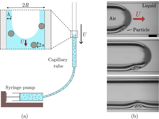
We connect one end of the capillary tube to a syringe filled with the dilute suspension. The other end of the capillary tube is open to the atmosphere. The suspension is first injected in the capillary and then withdrawn at a constant flow rate using a syringe pump. Withdrawing the suspension, instead of injecting compressible air, allows us to reach a constant velocity of the air-liquid front quickly. The velocity of the air-liquid interface is directly related to the withdrawal flow rate through the relation and is also measured by image processing using ImageJ. To visualize the motion of the suspension, the air-liquid meniscus, and the particles deposited on the wall of the capillary, we use a backlight LED Panel (Phlox). The motion and the final morphology of the coating film are recorded with a DSLR camera (Nikon D5300) and, when needed, with a high-speed camera (Phantom VEO 710L) equipped with a macro-lens (Nikkor 200mm) and microscopic lens (Mitutoyo). The curved surface of the cylindrical glass capillary tube leads to optical distortion, and does not allow clear visualization of the liquid film and of the particles deposited on the inner wall. Therefore, we inserted the cylindrical capillary tube in a square capillary, and injected glycerol between the capillaries as its refractive index matches the index of the borosilicate glass. This method ensured that the optical distortions due to the curved walls of the inner capillary are avoided Zhao et al. (2018). The threshold velocity for particle entrainment in the coating film is determined as the average of the largest value of the air/liquid front velocity where no isolated particles are visible in the film and the smaller value of the air/liquid front velocity where individual particles are entrained.
An example of the experiment is shown in Fig. 1(b), where air invades the capillary tube in the presence of particles. We observe that (i) the particle reaches the meniscus, (ii) deforms the liquid/air interface, and (iii) is entrained in the coating film whereas its diameter is larger than the film thickness. After being deposited, the particle strongly deforms the film and does not move anymore, coating the inner wall of the tube. This example shows that particle of diameter larger than the film thickness can be entrained contrary to the situation of two rigid boundaries where sieving effects would occur Sauret et al. (2014); Dressaire and Sauret (2017); Sauret et al. (2018).
III Results
III.1 Coating of Newtonian fluids
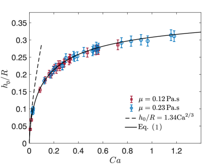
We first performed the experiments without particles for two silicone oils of different viscosities in a capillary tube of radius . The experimental data, reported in figure 2, are captured by the Taylor’s law [Eq. (1)] in the entire range of capillary numbers considered here Balestra et al. (2018); Aussillous and Quéré (2000). Besides, the prediction given by , valid in the limit of small capillary numbers , agrees with the Taylor’s law, within around 10%, for . We shall see later that for the experimental parameters considered here the entrainment of particles dispersed in the liquid occurs for capillary numbers , thus the Bretherton’s law, , is expected to give a good prediction and will be used in the following.
III.2 Deposition threshold of particles in the coating film
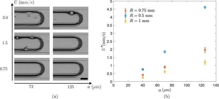
The no-deposition and deposition regimes are illustrated in Fig. 3(a). At low front velocity , no particles are visible in the film. Particles start to be entrained in the film beyond a threshold velocity . The particles are randomly dispersed, and the number of particles per surface area increases with the velocity. The threshold velocity depends both on the radius of the particles and the radius of the tube [Fig. 3(b)]. The situation observed here is reminiscent of the results reported for dip coating Sauret et al. (2019). Besides, for every configuration considered here, particles are able to squeeze into films thinner than the particle diameter.
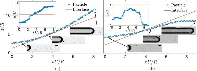
Examples of the time-evolution of the position of a particle are reported in Fig. 4(a) and 4(b) for the no-deposition and deposition regimes, respectively. When a particle is not entrained in the film, it first approaches the interface before recirculating in the bulk [inset of Fig. 4(a)]. In this regime, all particles follow similar dynamics. The entrainment case exhibits different dynamics, as illustrated in Fig. 4(b). The particle first approaches the interface in a similar way, but the velocity of the particle remains smaller than the front velocity. The particle is then entrained in the coating film where it reaches a zero velocity in the frame of reference of the laboratory, i.e., and the particle is deposited on the inner wall of the capillary [inset of Fig. 4(b)]. Once deposited on the tube inner wall, the particle is trapped between the wall and the air/liquid interface so that it does not move anymore and remains deposited.
These two distinct behaviors suggest that the presence of a stagnation point on the air/liquid front is a key parameter. Indeed, the streamlines ending at this location separate the region where the fluid flows into the film and a recirculation region within the bulk. Therefore, we expect that the thickness at the stagnation point is the relevant parameter that controls the entrainment of particles in the film Colosqui et al. (2013); Sauret et al. (2019).
IV Discussion
IV.1 Theoretical thickness at the stagnation point
We consider the air invasion in a cylindrical tube in the limit leading to the deposition of a film of uniform thickness on the wall. The thickness also corresponds to the thickness observed far from the front and rear menisci during the translation of a long bubble Bretherton (1961). In this limit, the lengthscale , associated with the meniscus, and , associated with the liquid film thickness far from the meniscus, satisfy and Bretherton (1961). Besides, , so that locally the situation is 2D and we use the cartesian coordinates system (, ), where is along the capillary and is oriented inward. The interface is given by , and the front is translating at the velocity . The Reynolds number remains small and we use the Stokes’ equations in the lubrication analysis:
| (2a) | |||||
| (2b) | |||||
| (2c) | |||||
On the wall of the capillary tube, the velocity field satisfies no-slip boundary conditions, so that in the reference frame moving with the air/liquid front and . The boundary conditions at the free surface at the leading order in are and , where . Equation 2(c) shows that the pressure field is only a function of . Integrating equation 2(b) twice with respect to , and using the boundary conditions leads to:
| (3) |
To simplify this expression, we consider the classical lubrication equation (see e.g., Eggers and Fontelos, 2015)
| (4) |
In the reference frame moving with the front at the velocity , the solution is of the form . The previous equation can be integrated with respect to together with the boundary conditions and so that
| (5) |
which corresponds to the canonical Landau–Levich–Derjaguin–Bretherton equation. The velocity of the interface is obtained using Eq. (3) and Eq. (5) and by setting :
| (6) |
The surface velocity changes sign along the interface at least once since far from the meniscus, i.e., , so that , and for , i.e., at the meniscus, so that . The thickness at the stagnation point corresponds to the point where the surface velocity vanishes, leading to
| (7) |
This result is similar to the dip coating of a plate Sauret et al. (2019) and a fiber Dincau et al. (2020). Note that this analytical results applies, a priori, only when the Bretherton law is valid, i.e., and .
IV.2 Numerical simulation
We performed numerical simulations of the fluid flow to characterize the prefactor in the range of , where particles are experimentally entrained. The model relies on the method developed by Balestra et al. Balestra et al. (2018) and uses a laminar two phase-flow approach with moving mesh, where the fluid-fluid interface is resolved in each step by an Arbitrary Lagrangian-Eulerian (ALE) method. The initial velocity of the outer liquid is imposed as . then denotes the average velocity on the surface of the droplet. The capillary number associated with the droplet is given by , where is the surface tension at the interface of the droplet and is the viscosity of the surrounding liquid. The ratio between the inner and outer viscosity, , was fixed at 0.01 since it has been shown that this value of gives the same flow profile and film thickness as those obtained at smaller values of Balestra et al. (2018). The ratio of densities does not affect the results and is thus set to 1. The model converges to a stationary solution when the droplet reaches its equilibrium shape and moves with a steady velocity . The moving mesh helps to avoid large deformations of the mesh associated with the moving droplet. Furthermore, the problem is solved in the moving frame of reference attached to the droplet, the droplet hence practically does not change its position. The inlet in the model is imposed as a laminar Poiseuille flow, with mean velocity . The velocity at the walls is imposed as , and the velocity of the bubble is determined and recalculated at each time step. We benchmarked the code by ensuring that the numerical simulation recovered the experimental results of Aussillous & Quéré for Aussillous and Quéré (2000). More details on the numerical procedure can be found in Ref. Balestra et al. (2018).
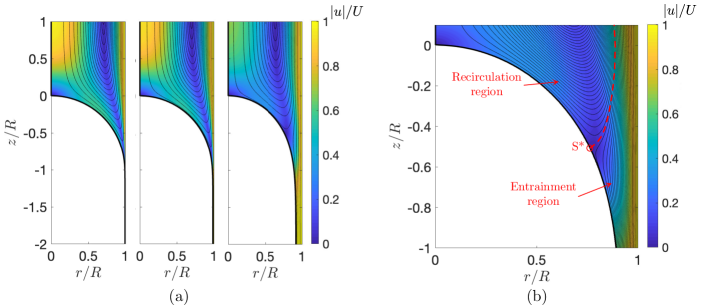
Examples of streamlines observed numerically are shown in Fig. 5(a) for various capillary numbers. The numerical results report that the main features of the flow remain similar, but the thickness of the liquid film on the wall of the capillary increases when increasing the capillary number. Fig. 5(b) shows a zoom in the region surrounding the stagnation point that delimitates the region where the fluid flows into the film and a recirculation region within the bulk.
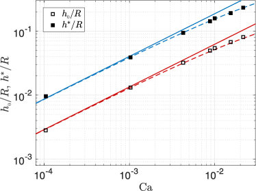
We measure the thickness in the uniform film region. The stagnation point corresponds to the location at the interface where the surface velocity vanishes allowing us to measure . The dimensionless thicknesses and are reported in Fig. 6. The simulations agree with the theoretical expression (7). Furthermore, the numerical results demonstrate that the coefficient obtained analytically can also be used with the Taylor’s law given by Eq. (1) for a better prediction of for so that:
| (8) |
IV.3 Entrainment threshold
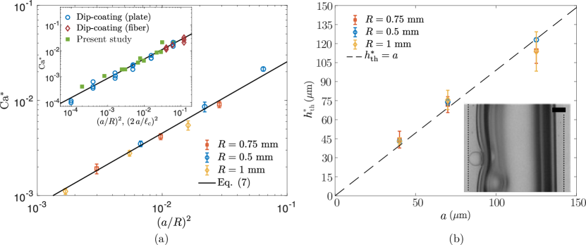
Fig. 7(a) reports that the threshold capillary number for particle entrainment increases with . The larger the particle is, the larger the coating film must be, and thus the associated capillary number, to entrain the particle. A particle is entrained if the thickness at the stagnation point is larger than a fraction of the particle diameter leading to the condition , where . The particle can be entrained only if it follows the streamlines entering the coating film, corresponding to the condition . Besides, if the particle does not deform the air/liquid interface, no capillary force is exerted on the particle, which will always be entrained in the film, so that an upper bound is . Assuming that an isolated particle does not significantly modify the flow topology and using Eq. (8), we obtain the capillary threshold value for particle entrainment:
| (9) |
Fig. 7(a) shows that all the experiments performed collapse on a master curve given by Eq. (9), where . The coupling of the liquid/air interface and the particle is complex. However, we can provide some rationalization of the value of by considering the force acting on the particle near the stagnation point that controls its entrainment into the coating film.
IV.4 Force acting on the particle near the stagnation point
The entrainment of the particle is initially controlled by the passive advection of the particle that follows the streamlines. Once the particle approaches the stagnation point, the experimental observations show that the particle strongly deforms the air/liquid interface. The particle is assumed to be in contact with the substrate, owing to its surface roughness of order 100 nm Deboeuf et al. (2009); Lubbers et al. (2014). Therefore, the entrainment of a particle is governed by the competition between the interfacial force, the viscous drag, and the friction on the substrate. The three phases situation (particle, air, liquid) leads to a complex interplay, and we try here to estimate the forces acting on the particle. The experimental results show that the entrainment threshold occurs for a thickness at the stagnation point of the same order as the particle radius [Fig. 7(b)]. Therefore, we consider the force acting on a particle of radius located at the stagnation point of thickness . We further assume that far from the particle, the interface has a shape similar to the situation without particle.
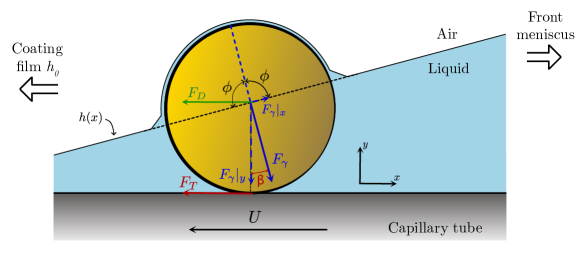
A schematic of a particle fully wetted by a liquid of thickness around the stagnation point is shown in Fig. 8. Below, we detail the amplitude and orientation of the different forces to estimate their influence on particle entrainment. We consider the situation in the frame of reference moving with the front. Besides, close to the entrainment threshold, the velocity of the particle nearly vanished at the stagnation point before being able to be entrained in the coating film. The experimental parameters imposed that inertial effects are negligible since .
An estimate of the viscous drag acting on the particle can be obtained by considering the average viscous stress acting on the particle: Lubbers et al. (2014). Furthermore, the viscous stress acts over half of the particle since so that the total drag is of order
| (10) |
The drag force acts along the -axis and acts as a driving force to entrain the particle (see Fig. 8).
Since the particle is totally wetted by the liquid (contact angle: ), the capillary force is acting downard, pushing the particle against the wall of the capillary tube. The amplitude of the capillary force is given by (see, e.g., Gómez-Suárez et al. (2001)):
| (11) |
where is the radius of the particle, the interfacial tension, the filling angle and here since the silicone oil perfectly wets the particle. For a liquid film of thickness , the absolute value of the amplitude of the capillary force reduced to . The capillary force is maximum for , corresponding to , so that an order of magnitude of the capillary force acting on the particle is
| (12) |
As illustrated in Fig. 8 the capillary force can be decomposed in its component that pushes the particle toward the surface of the capillary tube
| (13) |
and an axial force acting to keep the particle in the liquid reservoir (in the direction of the front):
| (14) |
The angle comes from the inclination of the air/liquid interface between the front and the region of uniform coating thickness. Note that we have neglected the radial curvature of the capillary since both and are very small compared to . The slope at the interface close to the stagnation point is obtained by linearizing the Landau-Levich-Derjaguin-Bretherton (LLDB) equation for the thickness Colosqui et al. (2013); Landau and Levich (1942):
| (15) |
As a result, an approximate solution of the slope is . In the range of parameters considered here leading to the entrainment of the particles , so that .
The resistance of the particle motion when the front is advancing and trapping of the particle at the stagnation point occurs because the particle becomes in physical contact with the glass substrate Lubbers et al. (2014). The particle is thus subject to a dynamic friction , where is an estimate of the dynamic friction coefficient between the immersed polystyrene particle and the glass substrate Tapia et al. (2019) and denotes the normal force confining the particle against the substrate, i.e. the component of the capillary force given by Eq. (13). Therefore, the dynamic friction force, oriented along and opposed to the motion of the front, is
| (16) |
We can now estimate the order of the magnitude of the two opposite forces induced by the deformation of the interface by the particles. The -component of the capillary force tends to keep the particle within the bulk liquid, whereas the -component confine the particle and leads to the friction force that favors the particle entrainment during the translation of the air/liquid front. Using Eqs. (14) and (16) together with the expression of , leads to an order of magnitude of the ratio of these forces:
| (17) |
For the order of magnitude of capillary number leading to capillary entrainment in this study, , we found that this ratio is of order unity (between 0.8 and 1.85). Therefore, the effects of the capillary force induced by the deformation of the interface mostly balance each other.
Using the order of magnitude of the experimental parameters used in this study, we can estimate the drag force and the friction force that also contribute to entrain the particle in the coating film and the capillary force along that prevents the deposition of the particle in the coating film. An order of magnitude of the ratio of these two opposite effects is given by
| (18) |
The two components of the capillary forces mainly balance each other owing to the friction force induced by the contact of the particle on the wall. The main limitation to entrain the particle in the film is thus the possibility for a particle to follow the streamlines leading to the coating flow, corresponding to the condition as observed experimentally.
The value of is also in quantitative agreement with previous experiments on dip-coating of plates and thin fibers Sauret et al. (2019); Dincau et al. (2020) as reported in the inset of Fig. 7 (note that the because of the flat geometry, the relevant parameter for the plate configuration is to account for the difference in geometry). Therefore, the entrainment of particles in a coating film governed by a stagnation point is controlled by a universal mechanism for dip coating, coating of the inner wall of a tube, and is expected to hold for a confined air bubble in a perfectly wetting fluid. The translation of a long bubble beyond the entrainment threshold would lead to similar results, except that particles will first be trapped in the liquid film and then released in the liquid at the rear of the bubble. In particular, contrary to the recent experiments of Yu et al. Yu et al. (2018b), no attachment of particles at the air/water interface of the bubble would be observed because the liquid fully wets the particles.
We should emphasize that we have considered diluted suspension in this work so that particles can be considered as isolated Sauret et al. (2019). For larger volume fractions of the suspension, the entrainment of clusters may be observed as well as the accumulation of particles near the meniscus. We should emphasize that we have never observed clogging of the tube for the perfectly wetting fluid considered here, but we have observed, from time to time, the entrainment of some clusters near the entrainment threshold.
V Conclusion
In this article, we have shown that the liquid coating the inner wall of a capillary tube exhibits different regimes in the presence of particles: liquid only and deposition of particles. We demonstrated that a particle is entrained in the film even if its diameter is larger than the film thickness. Considering the thickness at the stagnation point, the experimental results have been quantitatively rationalized. In particular, we have provided some physical insights to rationalize the order of magnitude of the parameter . A similar physical mechanism underlies the entrainment of particles as observed in both this configuration and in dip coating Colosqui et al. (2013); Sauret et al. (2019). This result comes from the common features between this configuration and the dip-coating of a substrate, the most important of which is the presence of a stagnation point. Therefore, preventing the contamination of substrate by particles and biological microorganisms using this strategy, as reported for the dip coating system Sauret et al. (2019), is also valid in tubings and can provide guidelines for dispensing of suspensions and contaminated liquid in tubes. These results are also relevant to environmental processes involving the transport of small particles in confined geometries, such as the dissemination of colloid and microorganisms in porous media Saiers et al. (2003) and provide guidelines to improve the coating of tubings by suspensions Primkulov et al. (2020). This filtering mechanism could also be an ingredient to explain the increase of bubble rise speed observed recently in confined suspension Madec et al. (2020). The influence of the wettability of the particle can further refine the value of the prefactor and is the topic of an ongoing study.
Acknowledgements.
This material is based upon work supported by the National Science Foundation under NSF CAREER Program Award CBET No. 1944844 and by the ACS Petroleum Research Fund 60108-DNI9. We thank F. Gallaire and L. Keiser for their help with the numerical model and B. Dincau for a careful reading of the manuscript.References
- Ingham and Pop (1998) D. B. Ingham and I. Pop, Transport phenomena in porous media (Elsevier, 1998).
- Blunt (2001) M. J. Blunt, “Flow in porous media: pore-network models and multiphase flow,” Current Opinion in Colloid & Interface Science 6, 197–207 (2001).
- Koch and Hill (2001) D. L. Koch and R. J. Hill, “Inertial effects in suspension and porous-media flows,” Annual Review of Fluid Mechanics 33, 619–647 (2001).
- Schwarzkopf et al. (2011) J. D. Schwarzkopf, M. Sommerfeld, C. T. Crowe, and Y. Tsuji, Multiphase flows with droplets and particles (CRC press, 2011).
- Dressaire and Sauret (2017) E. Dressaire and A. Sauret, “Clogging of microfluidic systems,” Soft Matter 13, 37–48 (2017).
- Maxworthy (1989) T. Maxworthy, “Experimental study of interface instability in a hele-shaw cell,” Physical Review A 39, 5863 (1989).
- Strait et al. (2015) M. Strait, M. Shearer, R. Levy, L. Cueto-Felgueroso, and R. Juanes, “Two fluid flow in a capillary tube,” in Collaborative Mathematics and Statistics Research (Springer, 2015) pp. 149–161.
- Aussillous and Quéré (2000) P. Aussillous and D. Quéré, “Quick deposition of a fluid on the wall of a tube,” Physics of Fluids 12, 2367–2371 (2000).
- Magniez et al. (2016) J. C. Magniez, M. Baudoin, C. Liu, and F. Zoueshtiagh, “Dynamics of liquid plugs in prewetted capillary tubes: from acceleration and rupture to deceleration and airway obstruction,” Soft Matter 12, 8710–8717 (2016).
- Zhao et al. (2018) B. Zhao, A. A. Pahlavan, L. Cueto-Felgueroso, and R. Juanes, “Forced wetting transition and bubble pinch-off in a capillary tube,” Physical Review Letters 120, 084501 (2018).
- Hayoun et al. (2018) P. Hayoun, A . Letailleur, J. Teisseire, F. Lequeux, E. Verneuil, and E. Barthel, “Film thickness selection for partially wetting, low-viscosity liquids challenges the standard model of triple line dynamics,” arXiv preprint arXiv:1805.12030 (2018).
- Taylor (1961) G. I. Taylor, “Deposition of a viscous fluid on the wall of a tube,” Journal of Fluid Mechanics 10, 161–165 (1961).
- Reinelt and Saffman (1985) D. A. Reinelt and P. G. Saffman, “The penetration of a finger into a viscous fluid in a channel and tube,” SIAM Journal on Scientific and Statistical Computing 6, 542–561 (1985).
- Giavedoni and Saita (1997) M. D. Giavedoni and F. A. Saita, “The axisymmetric and plane cases of a gas phase steadily displacing a newtonian liquid-a simultaneous solution of the governing equations,” Physics of Fluids 9, 2420–2428 (1997).
- Balestra et al. (2018) G. Balestra, L. Zhu, and François Gallaire, “Viscous taylor droplets in axisymmetric and planar tubes: from bretherton’s theory to empirical models,” Microfluidics and Nanofluidics 22, 67 (2018).
- Bretherton (1961) F. P. Bretherton, “The motion of long bubbles in tubes,” Journal of Fluid Mechanics 10, 166–188 (1961).
- Muradoglu and Stone (2007) Metin Muradoglu and Howard A Stone, “Motion of large bubbles in curved channels,” Journal of Fluid Mechanics 570, 455 (2007).
- Hazel and Heil (2002) Andrew L Hazel and Matthias Heil, “The steady propagation of a semi-infinite bubble into a tube of elliptical or rectangular cross-section,” Journal of fluid mechanics 470, 91–114 (2002).
- Cueto-Felgueroso and Juanes (2012) L. Cueto-Felgueroso and R. Juanes, “Macroscopic phase-field model of partial wetting: bubbles in a capillary tube,” Physical Review Letters 108, 144502 (2012).
- Bonnoit et al. (2010) C. Bonnoit, J. Lanuza, A. Lindner, and E. Clement, “Mesoscopic length scale controls the rheology of dense suspensions,” Physical Review Letters 105, 108302 (2010).
- Furbank and Morris (2004) R. J. Furbank and J. F. Morris, “An experimental study of particle effects on drop formation,” Physics of Fluids 16, 1777–1790 (2004).
- Bonnoit et al. (2012) C. Bonnoit, T. Bertrand, E. Clément, and A. Lindner, “Accelerated drop detachment in granular suspensions,” Physics of Fluids 24, 043304 (2012).
- Château et al. (2018) J. Château, É. Guazzelli, and H. Lhuissier, “Pinch-off of a viscous suspension thread,” Journal of Fluid Mechanics 852, 178–198 (2018).
- Raux et al. (2020) Pascal S Raux, Anthony Troger, Pierre Jop, and Alban Sauret, “Spreading and fragmentation of particle-laden liquid sheets,” Physical Review Fluids 5, 044004 (2020).
- Buchanan et al. (2007) M. Buchanan, D. Molenaar, S. de Villiers, and R. M. L. Evans, “Pattern Formation in Draining Thin Film Suspensions,” Langmuir 23, 3732–3736 (2007).
- Lubbers et al. (2014) L. A. Lubbers, Q. Xu, S. Wilken, W. W. Zhang, and H. M. Jaeger, “Dense suspension splat: Monolayer spreading and hole formation after impact,” Physical Review Letters 113, 044502 (2014).
- Grishaev et al. (2017) V.r Grishaev, C. S. Iorio, F. Dubois, and A. Amirfazli, “Impact of particle-laden drops: Particle distribution on the substrate,” Journal of Colloid and Interface Science 490, 108–118 (2017).
- Xu et al. (2016) F. Xu, J. Kim, and S. Lee, “Particle-induced viscous fingering,” Journal of Non-Newtonian Fluid Mechanics 238, 92–99 (2016).
- Kim et al. (2017) J. Kim, F. Xu, and S. Lee, “Formation and destabilization of the particle band on the fluid-fluid interface,” Physical Review Letters 118, 074501 (2017).
- Luo et al. (2018) Rui Luo, Yun Chen, and Sungyon Lee, “Particle-induced viscous fingering: Review and outlook,” Physical Review Fluids 3, 110502 (2018).
- Xu and Lee (2019) Feng Xu and Sungyon Lee, “The enhancement of viscous fingering with bidisperse particle suspension,” Journal of Fluid Mechanics 860, 487–509 (2019).
- Kudrolli et al. (2020) Arshad Kudrolli, Rausan Jewel, Ram Sudhir Sharma, and Alexander P Petroff, “Unstable invasion of sedimenting granular suspensions,” Physical Review Letters 125, 054501 (2020).
- Madec et al. (2020) Christopher Madec, Brivaël Collin, J Jerome, and Sylvain Joubaud, “Puzzling bubble rise speed increase in dense granular suspensions,” Phys. Rev. Lett. (in press) (2020).
- Yu et al. (2017) Y. E. Yu, S. Khodaparast, and H. A. Stone, “Armoring confined bubbles in the flow of colloidal suspensions.” Soft Matter 13, 2857–2865 (2017).
- Yu et al. (2018a) Y. E. Yu, S. Khodaparast, and H. A. Stone, “Separation of particles by size from a suspension using the motion of a confined bubble,” Applied Physics Letters 112, 181604 (2018a).
- Gans et al. (2019) A. Gans, E. Dressaire, B. Colnet, G.e Saingier, M. Bazant, and A. Sauret, “Dip-coating of suspensions,” Soft Matter 15, 252–261 (2019).
- Palma and Lhuissier (2019) S. Palma and H. Lhuissier, “Dip-coating with a particulate suspension,” Journal of Fluid Mechanics 869 (2019).
- Colosqui et al. (2013) Carlos E Colosqui, Jeffrey F Morris, and Howard A Stone, “Hydrodynamically Driven Colloidal Assembly in Dip Coating,” Physical Review Letters 110, 188302 (2013).
- Sauret et al. (2019) A. Sauret, A. Gans, B. Colnet, G. Saingier, M. Bazant, and E. Dressaire, “Capillary filtering of particles during dip coating,” Physical Review Fluids 4, 054303 (2019).
- Dincau et al. (2019) B. M. Dincau, M. Z. Bazant, E. Dressaire, and A. Sauret, “Capillary sorting of particles by dip coating,” Physical Review Applied 12, 011001 (2019).
- Dincau et al. (2020) Brian M. Dincau, Ethan Mai, Quentin Magdelaine, Alex J. Lee, Martin Bazant, and Alban Sauret, “Entrainment of particles during the withdrawal of a fibre from a dilute suspension,” Journal of Fluid Mechanics 903 (2020).
- Boyer et al. (2011) F. Boyer, E. Guazzelli, and O. Pouliquen, “Unifying suspension and granular rheology,” Physical Review Letters 107, 188301 (2011).
- Guazzelli and Pouliquen (2018) Élisabeth Guazzelli and Olivier Pouliquen, “Rheology of dense granular suspensions,” Journal of Fluid Mechanics 852 (2018).
- Sauret et al. (2014) Alban Sauret, Erin C Barney, Adeline Perro, Emmanuel Villermaux, Howard A Stone, and Emilie Dressaire, “Clogging by sieving in microchannels: Application to the detection of contaminants in colloidal suspensions,” Applied Physics Letters 105, 074101 (2014).
- Sauret et al. (2018) Alban Sauret, Katarzyna Somszor, Emmanuel Villermaux, and Emilie Dressaire, “Growth of clogs in parallel microchannels,” Physical Review Fluids 3, 104301 (2018).
- Eggers and Fontelos (2015) Jens Eggers and Marco Antonio Fontelos, Singularities: formation, structure, and propagation, Vol. 53 (Cambridge University Press, 2015).
- Deboeuf et al. (2009) Angélique Deboeuf, Georges Gauthier, Jérôme Martin, Yevgeny Yurkovetsky, and Jeffrey F Morris, “Particle pressure in a sheared suspension: A bridge from osmosis to granular dilatancy,” Physical review letters 102, 108301 (2009).
- Gómez-Suárez et al. (2001) Cristina Gómez-Suárez, Henk J Busscher, and Henny C van der Mei, “Analysis of bacterial detachment from substratum surfaces by the passage of air-liquid interfaces,” Applied and environmental microbiology 67, 2531–2537 (2001).
- Landau and Levich (1942) L. D. Landau and B. V. Levich, “Dragging of a liquid by a moving plate,” Acta Physicochimica URSS 17, 42 (1942).
- Tapia et al. (2019) Franco Tapia, Olivier Pouliquen, and Élisabeth Guazzelli, “Influence of surface roughness on the rheology of immersed and dry frictional spheres,” Physical Review Fluids 4, 104302 (2019).
- Yu et al. (2018b) Yingxian Estella Yu, Lailai Zhu, Suin Shim, Jens Eggers, and Howard A Stone, “Time-dependent motion of a confined bubble in a tube: transition between two steady states,” Journal of Fluid Mechanics 857 (2018b).
- Saiers et al. (2003) James E Saiers, George M Hornberger, Drew B Gower, and Janet S Herman, “The role of moving air-water interfaces in colloid mobilization within the vadose zone,” Geophysical research letters 30 (2003).
- Primkulov et al. (2020) BK Primkulov, AA Pahlavan, L Bourouiba, JWM Bush, and R Juanes, “Spin coating of capillary tubes,” Journal of Fluid Mechanics 886 (2020).