TEL: Low-Latency Failover Traffic Engineering in Data Plane
Abstract
Modern network applications demand low-latency traffic engineering in the presence of network failure, while preserving the quality of service constraints like delay and capacity. Fast Re-Route (FRR) mechanisms are widely used for traffic re-routing purposes in failure scenarios. Control plane FRR typically computes the backup forwarding rules to detour the traffic in the data plane when the failure occurs. This mechanism could be computed in the data plane with the emergence of programmable data planes.
In this paper, we propose a system (called TEL) that contains two FRR mechanisms, namely, TEL-C and TEL-D. The first one computes backup forwarding rules in the control plane, satisfying max-min fair allocation. The second mechanism provides FRR in the data plane. Both algorithms require minimal memory on programmable data planes and well-suited with modern line rate match-action forwarding architectures (e.g., PISA). We implement both mechanisms on P4 programmable software switches (e.g., BMv2 and Tofino) and measure their performance on various topologies. The obtained results from a datacenter topology show that our FRR mechanism can improve the flow completion time up to 4.6x–7.3x (i.e., small flows) and 3.1x–12x (i.e., large flows) compared to recirculation-based mechanisms, such as F10, respectively.
Index Terms:
Traffic engineering, network monitoring, programmable data plane, low-latency, link failure, reinforcement algorithm.I Introduction
Recent cloud datacenters run numerous applications on their networks that are interconnected through several servers. The applications have low-latency requirements and demand fast rerouting in the case of any failure. To address these requirements, Fast Re-Route (FRR) mechanisms are widely used to reroute the traffic [1]. Control plane FRR typically computes the backup forwarding rules to detour the traffic in the data plane when the failure occurs. This proactive way of maintaining the backup forwarding rules in the switches improves the network robustness and availability.
The control plane FRR solutions are widely adopted by the network equipment vendors. Such solutions allow the network administrators to implement the network functionalities as a black-box option [1]. Nevertheless, these mechanisms provide less flexibility to the network operators for customized packet processing. Recent advances in programmable data planes [2] offer flexible packet header processing, which is useful in many use-cases, including network monitoring [3], and traffic load balancing [4] to state few examples. Packet recirculation can be used as a simple mechanism in the programmable pipelines to detour the traffic to the pipeline’s input port. Then, the pipeline can select the different egress port when the failure is detected. However, this solution decreases the packet processing throughout and increases its latency [1].
Some business networking applications have stringent Quality of Service (QoS) requirements such as latency and bandwidth. Control plane FRR solutions could satisfy the QoS requirements by using mechanisms such as max-min fair allocation [5, 6]. In contrast, data plane solutions are fast in rerouting the traffic but unaware of QoS constraints dictated by the traffic policies. The reason is that the selected nodes in the path may not have enough capacity to steer the traffic.
I-A Motivations
In literature, several schemes exist to deal with link failures in programmable data plane [1, 7, 8, 9, 10, 11, 12]. For instance, F10 [12] recirculates the traffic of failed ports until an alternative port is explored. However, packet recirculation has a low performance [1]. Besides, the authors in [1] create a set of new FRR primitives and implement them in P4 [2] to preserve high availability and low latency. Blink [10] is a fast data-driven remote failures algorithm to deal with inter-domain failures in P4. It tracks failure signals and monitors the link rate to reroute the traffic automatically. FlexGate [11] proposes a rule placement algorithm to mitigate the link failure on various network functions at high throughput. Nevertheless, none of these approaches simultaneously consider the control plane and data plane FRR mechanisms. Motivated by these considerations, our intention in this paper is to propose two FRR mechanisms that implement on control- and data planes simultaneously. The first one is a control plane-based mechanism that preserves QoS requirements using max-min fair allocation (i.e., traffic engineering). The second one provides low-latency FRR in the data plane. Both mechanisms require minimal memory on programmable data planes and well-suited with modern line rate match-action forwarding architectures (e.g., PISA). Specifically, we respond to the following questions: i) Is it possible to provide failover traffic engineering? (see Section II) ii) How can we preserve a set of QoS constraints in the steering traffic of different users? (see Section III-B) And, iii) How can we solve the max-min fair allocation problem in a linear time? (see Section III-B).
I-B The goal of the paper and contributions
We propose two FRR mechanisms, i.e., one in the control plane and one in the data plane, to detour the traffic in the case of failure. The control plane solution, TEL-C, can satisfy max-min fair allocation in assigning flows to the network links. This solution is a proactive solution and should be executed before network operations. To accomplish this, we use the Distributed Learning Automaton (DLA) to explore the paths while considering multiple QoS constraints, such as delay and capacity of the link. This problem is known to be an NP-hard problem [13], and our approach finds each candidate solution in linear time. It is an iterative approach to find the best optimal path among all possible paths.
The second solution, TEL-D, is similar to the state-of-the-art data plane solutions. In this solution, we select a random egress port from the available list of ports to reroute the traffic when a failure occurs. It is well-suited in datacenter topologies.
The proposed solutions avoid recirculations and lead to the following goals:
-
•
Low latency and high throughput: In case of failure, the traffic will rapidly reroute to the next available port without performance degradation and irrespective of the number of failures.
-
•
Memory cost: Our proposed FRR mechanisms occupy minimal memory on the P4-enabled devices.
-
•
Flexibility: The proposed FRR mechanisms could guarantee a set of link failures. It provides two sets of primary and backup forwarding rules.
Hence, we summarize our main contributions as follows:
-
•
We formalize the traffic engineering with QoS requirements as a max-min fair allocation problem.
-
•
To solve it, we propose a control-based FRR mechanism using a reinforcement learning algorithm that selects shortest paths using DLA, which finds primary and backup paths for each traffic demand of each network application/service.
-
•
We propose a data plane FRR mechanism that can be used as an FRR primitive in programmable data planes.
-
•
We checked the feasibility of both FRR mechanisms in P4 and BMv2 and Tofino software switches.
-
•
Finally, we evaluate our solutions on various topologies. To be precise, we compare TEL-C against Yen’s K-shortest path algorithm on the length of shortest paths, the algorithms’ running time and traffic load. Also, our evaluation on a datacenter topology shows that TEL-D can improve the Flow Completion Time (FCT) up to 4.6x–7.3x (i.e., small flows) and 3.1x–12x (i.e., large flows) compared to recirculation-based mechanisms, such as F10 [12], respectively.
I-C Roadmap
We organize the paper below. Section II describes the system model explaining the optimization problem. In Section III, we present our FRR mechanisms. Section IV presents the proof-of-concept in P4-enabled devices. The simulation results are presented in Section V. We explain the practical appliance of our proposed FRR mechanisms in Section VI. The related work comes in Section VII. Finally, we conclude our work in Section VIII.
II System Model
| Type | Symbol | Definition | Type - Unit | Appears in Eq. |
|---|---|---|---|---|
| Set | Set of P4 switches, where | - | - | |
| Set of edges, where | - | - | ||
| Set of paths | - | - | ||
| Set of flows | - | - | ||
| Index | Index of flow, | Integer - [units] | - | |
| Index of node/switch, | Integer - [units] | - | ||
| Index of node/switch, | Integer - [units] | - | ||
| Required bandwidth for flow | Continuous - [bps] | (1) | ||
| Crossing traffic ratio to total bandwidth of each link | Continuous - [units] | (1) | ||
| Input Parameters | Matrix of link bandwidth between switch and | Continuous - [bps] | (1) | |
| Network resource assignment matrix between switch and for flow | Binary - [units] | (1),(2),(3),(4) | ||
| Source switch for flow | Continuous - [units] | (2) | ||
| Destination switch for flow | Continuous - [units] | (2) | ||
| Maximum tolerable delay for path | Continuous - [ms] | (3) | ||
| Propagation delay between switch and | Continuous - [ms] | (3),(6) | ||
| Bandwidth usage between switch and | Continuous - [bps] | (6) | ||
| Cost of flow while crossing switch and | Continuous - [units] | (5) | ||
| Steering traffic cost between switch and | Continuous - [units] | (5), (6) | ||
| ,, | Coefficients | Continuous - [units] | (6) | |
| Var | Network resource assignment matrix between node and | Continuous - [units] | (6) | |
| A path from to | Continuous - [units] | (3), (5) |
In this section, we formalize the traffic engineering with QoS requirements as a max-min fair allocation problem. Then, we define an objective function to proactively find paths for flows over multiple rounds. Finally, we give an example for the problem before and after a link failure. Table I presents the main notation used in the paper.
II-A Link Capacity, Flow Conservation, Delay, and Cost
We assume that we have bi-directed graph where is a set of P4 switches which are connected to each other (where, ) and is a set of edges where . Also, we can transfer a set of flows between two pairs of switches.
Link capacity. Equation (1) ensures the link capacity between each pair of P4 switches ( and ). Let be a single flow crossing link and , .
| (1) |
where is the required bandwidth for the -th flow; is a ratio of crossing traffic to total bandwidth of each link; is the matrix of link bandwidth between and , and is the network resource assignment matrix between and for the flow .
Flow conservation. Equation (2) indicates the flow conservation and its limitation applied in the presented topology. If a flow leaves its source switch , then it can not return to the source (no loop– see the first equality). If a flow enters a destination switch , it remains there (see the second equality). Finally, the total input flows from a node should be the same as the total output flows on the same node () (see the third equality).
| (2) |
Propagation delay. We can control the propagation delay of each flow within a path using Eq. (3). This equation ensures that the total delay of encountered pair switches per-flow of a path should be at most equal to maximum tolerable delay for each or . Equation (3) satisfies loop prevention for each flow . This equation ensures that the delay of the path is less than the threshold value .
| (3) |
where is the propagation delay of link ; is a path from to consisting a set of links between a source and a destination. Equation (4) ensures that each flow crosses each link once.
| (4) | |||
Cost. We model the cost of steering traffic flows from path as follows.
| (5) |
where is the cost of flow while crossing link .
II-B Objective Function
Our main objective is to allocate the flows according to the available resources using max-min fair allocation. Equation (6) calculates this function which implies the weighted function per link .
| (6) |
where the fraction is the bandwidth utilization (or link utilization) and is the cost of steering traffic from switch to (it is an input of the problem); , and are the coefficients and have values between 0 and 1. In this way, if the priority is given to the delay, we require to define high ratio for . Otherwise, if the link cost is the highest priority we need to provide higher ratio for , and finally, if link utilization is the importance criterion for the application, we need to have higher value for coefficient in the objective function. Herein, we state some example use-cases. Many cloud service providers, e.g., Google, Amazon, Microsoft, offer network services with different QoS requirements to the users in different locations [14]. For example, network services that offer critical business transactions are sensitive to delay and bandwidth rather than cost. While other services, offered by Content Delivery Network (CDN) providers, that transfer a large volume of data dictate high data transmission cost [15, 16]. Furthermore, in 5G use-cases, we require to provide Ultra-Reliable Low-Latency Communication (URLLC) channel to satisfy mobile users’ demands [17]. Therefore, depending on the use-case, the coefficient for the different parameters can be set.
Here, we apply a max-min fair allocation [18] considering the for each link. The network administrator can select the related coefficient of network latency and bandwidth usage according to the network (flow) requirements. Specifically, large flows demand high bandwidth while the short flows are sensitive to delays. Therefore, according to the flow sizes, desired values for the coefficients of the participant terms in (6) are adjusted. The QoS is a priority given to each flow according to the application requirements. For example, an application can request low transmission delay [19].
Definition: Flow bottlenecks at link if the following conditions occur:
-
1.
;
-
2.
Flow obtains the maximum rate of all flows crossing link .
Running example: Fig. 1 presents a network without failure with 3 links carrying 2 flows. The max-min fair allocation of flow 2 (red) with , which is bottlenecked at link , and flow 1 (green) with , which is bottlenecked at link . Link has spare since (green) flow 2 is bottlenecked elsewhere.
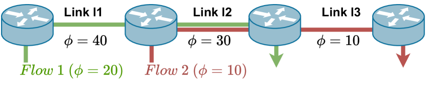
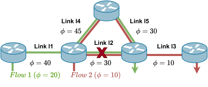
Fig. 2 illustrates max-min fair allocation in the the presence of a link failure (). The traffic steers from links and after failing to link with satisfying the max-min fair allocation.
III TEL: The Solution
In this section, we describe our contribution to failover traffic engineering. After modeling the network requirements, we should gather the network information to find the best paths while preserving the QoS constraints. We first explain TEL-C. Then, we describe TEL-D (see Section III-D). TEL-C has three different phases, namely, network monitoring, path selection and rule generation. In the first phase (Section III-A), the information of the network is collected by the P4 runtime to use it as the input for the path selection phase. We select unique shortest paths for network services/applications using the concept of DLA to carry the flows in the path selection phase (see Section III-B). Finally, TEL-C generates a set of proper forwarding rules according to the chosen shortest paths in the previous phase (see Section III-C).
III-A Network Monitoring
To obtain the network information, we should send a set of probe packets periodically to the network. These packets can be sent either by the controller or end-hosts because there is no packet generation mechanism available in a P4-enabled device. We use P4 runtime to obtain the information on the network. The controller of TEL uses probe packets to get network information like the propagation delay and bandwidth. Each probe packets contains a set of fields used to collect the link information. The information of links is cloned to the controller to build the network topology. The time to send such probe packets can be tuned depending on the user’s needs. However, the path selection phase requires network information before applying the selection procedure. We also assume that the network topology is known in advance to the controller.
III-B Path Selection
Selecting an optimal forwarding path with multi-constrained QoS requirements is a well-known NP-hard problem [13], and we limit NP-hard discussions here. Instead, we focus on the detail of our approach. We use the concept of DLA, which is a reinforcement learning approach to solve a problem. Each DLA is a network of Learning Automaton (LA). LA is used for learning simple actions using some simple agents. However, its functionality is limited to the purpose of this work while considering several network-related parameters. Interestingly, DLA is composed of a network of LAs and can be applied to complex network problems. Therefore, for the need of this paper, we adopted a DLA solution. Also, the convergence of a solution using DLA was proven by using Martingale Theorem [20].
In the LA concept, there is a set of actions for each LA to pick at any time, and the LA randomly selects one of them. There is a probability associated with each action. The random environment supplies the reinforcement signal to the chosen action of an LA agent. The LA updates the action probability based on the received signal. This is called the training phase of LA, like the other reinforcement learning-based mechanisms. When the learning phase ends, the LA selects the best action among the available actions. To do so, the LA checks the probability of its actions and returns the action’s index with the highest probability as the best action.
We create a corresponding DLA graph of the network graph. Each node in the DLA graph has an LA helping it to choose the best action. The number of actions for each LA is equal to the number of outgoing edges from each node in the network graph. The initial probability of each action is . Selecting an action by the LA of each node corresponds to selecting a neighbor node in the network graph.
Specifically, in this paper, we utilize variable-structure automata [21] on a P-model LA ( is a fixed value: zero or one). We select this automaton because we require to decide if the explored path is better than the previous one (a binary decision).
Let and be the action probability vectors at the and round of learning, respectively. Hence, we define learning algorithm in Eq. (7):
| (7) |
We define the operation of the LA below. Considering as an action probability vector, the LA arbitrarily chooses an action and applies it to the environment. When we receive the feedback from the environment, the LA algorithm updates its action probability vector using Eq. (8) for and (9) for :
| (8) | ||||
| (9) | ||||
where is the number of actions; is the probability of action ; is the probability of action ; is the reward, and is the penalty parameters, respectively.
Algorithm 1 presents the pseudo code of our path selection algorithm. This algorithm runs in several iterations (lines 1-1), and the DLA explores a solution among all the candidate solutions in each iteration. Here, the DLA finds a path from a source to a destination from the network graph . At the end of each iteration, the chosen path is examined based on Eq. (6) (see line 1). If the result of evaluating the current path’s objective function is better than the previous value, the environment generates a reward for the selected path. Then, all the chosen actions by the LA of each node are rewarded based on Eq. (8) that results in placing all the chosen nodes in as the best-selected path until now (see line 1). This procedure continues until the stop condition is met. We define a fixed integer value of as the stop condition (see line 1). The nodes in the will be chosen as the path for the requested traffic flow. At the end of this phase, Algorithm 2 updates the capacity of the links in the network graph by applying the requested flow in the chosen path . After finding a path for each flow request, the network graph should be updated with a new objective function. Thus, this parameter varies over time, and DLA learns to choose the best paths for the flows using the updated network graph.
Running the above procedure results in a path selection. In a provider network which has different service demands, we need to select a path for each one. To do so, we repeat the same procedure times to find a path for each requested service.
Pruning rules. We use a Boolean value along with each action of LA to determine if the action can be chosen by the DLA. The LA can select an action if and only if the corresponding value to that action is . We apply several pruning rules to speed up the running time of the algorithm and its convergence as follows:
-
•
The corresponding actions of the nodes that are selected in each iteration are disabled. This helps in reducing the search space in the DLA graph. At the end of each iteration, all the disabled actions are enabled again to contribute to the next round of the path selection process. Disabling the corresponding action of the chosen edge avoids any routing instability. It also helps to improve the convergence of the algorithm.
-
•
The DLA removes a node from the currently selected path if there is no possible action selected from that node. This rule prevents dead-end path selection in each round.
-
•
We disable the corresponding actions of the links in each LA that do not have spare bandwidth to place other flows. This rule prevents capacity oversaturation.
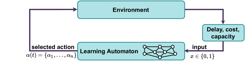
Fig. 3 presents the interaction of LA and the random environment in the DLA theory. The adjacency list of each node in the network graph forms the action-list of each LA. We also add the relevant parameters of TEL-C to show how they interact. We prune each LA’s action list to speed up the convergency of LA to the optimal action. In such cases, if an action of LA is disabled during an iteration, then the probability of that action remains unchanged while the probability of other action updates according to Eq. (8).
Time complexity of path selection. We describe the time complexity of Algorithm 1. Each round of the DLA algorithm requires to find a path where is the number of edges in the DLA graph. This procedure repeats times to find the best path from a source to a destination. Thus, the running time of lines 1 to 1 is . However, we run this procedure times to find different paths. Therefore, the total running time of the path selection phase is .
The above time complexity show that TEL-C can solve the problem in a linear time by preserving the QoS constraints for different network applications.
III-C Rule Generation
The rule generation phase creates a proper set of table entries for the corresponding switches (i.e., the selected nodes) in each path. These rules should be installed on the switches using the P4 agent to steer the traffic. However, to differentiate the traffic of different flows that we use an ID for each path (see more detail in Section IV-B).
To generate the forwarding rules, we keep track of all paths from the sources to the destinations, including the intermediate nodes. There might be multiple paths available between each pair of sources and destinations, but TEL-C exploits the ones explored during the path selections phase. Therefore, to generate each forwarding rule for a given P4 switch, we have to check the proper egress port. Suppose that we have a path from . When we generate the forwarding rule for , we check the network graph for the egress port of that is connected to . Then, the egress port number of along with the source and destination IP addresses of this path is inserted as a forwarding rule into . We follow the same procedure for and in this path.
III-D TEL-D
TEL-C proactively computes paths, i.e., primary and backup using DLR by checking the network. A simplified version of the path selection algorithm of TEL-C without the need for the control plane interaction is called TEL-D. TEL-D is suitable for datacenter topologies where the servers are within a few hops distance from each other and link latencies are short. Thus, we use the basic idea of path selection in the DLA manner in TEL-D.
TEL-D firstly checks all the active ports when the failing occurs to find all the available active ports. We use one bit per port in each switch to set the status of them. By performing a XOR on the value of each port with 0b1, we check if the port is active. Following this operation for all ports, we can list all the available active ports. TEL-D randomly selects one of its outgoing egress ports and forwards the flows through that port. Algorithm 3 shows the pseudo code of TEL-D in detail.
IV Proof-Of-Concept
We implement path selection reported in Section III-B and rule generation (see Section III-C) parts of TEL-C in Python with around 600 lines of code. We now explain the architecture of TEL-C with the PISA switch model (see Section IV-A). Then, we explain the P4 code implementation (see Section IV-B). Finally, we briefly explain the TEL-D (see Section III-D).
IV-A TEL-C Architecture
Fig. 4 presents an abstraction of P4 PISA pipeline [22] with TEL-C. The P4 implementation of TEL-C is carried out in P4_16 [23] using the BMv2 [22] switch. It contains the control and data plane layers. The control plane is in charge of monitoring the network and selecting the paths according to the network requirements (see Section III). The data plane forwards the packets based on the forwarding rules generated by the control plane. The presented model in the data plane includes forwarding pipelines, namely, ingress and egress. In this figure, the network operators can configure the parser to match arbitrary packet header fields. Each pipeline includes a sequence of match-action stages. The ingress and egress pipelines can be programmed using P4 runtime as the control plane agent.
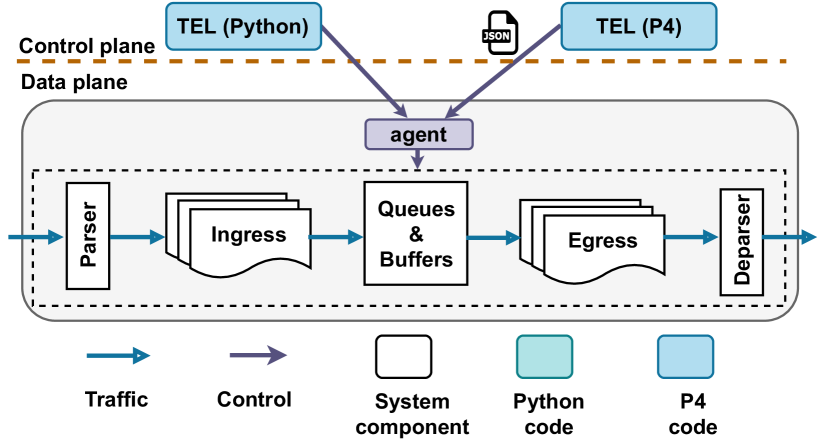
We compile the P4 implementation of TEL-C and generate the JSON representation to load on the switches. In this abstraction model, the forwarding rules for the switches are generated using the Python part of TEL-C.
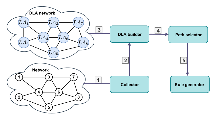
Fig. 5 depicts the internal architecture of TEL-C that is implemented in Python. In the beginning, the Collector component monitors the network and obtains the required information (see 1). To gather the network information, a set of probe packets are generated. Each switch replies to the probe packets accordingly. Then, the information are fed 3 into DLA builder component that makes the corresponding DLA graph from the network graph (see 4). The Path selector performs path selection using the DLA network and link information. TEL-C chooses each path according to the algorithm in Section III. After computing the paths, we need to generate the forwarding rules through Rule generator component and load them into the switches (see 5). We use the P4 local agent for this purpose. The switch is now ready to steer the network traffic.
IV-B P4 Implementation
To implement our solution in P4, we need to keep the state of all paths in each switch. We use the P4 registers for this purpose by assigning a bit for each path. We call this register path_status, which has 0 value to show a primary path and 1 to indicate the backup one. The overall number of bits is equal to the given number of paths for the topology, i.e., in Section III-B. We use bits for this purpose.
We use two tables to implement TEL-C. The first table, table_1, matches packets based on the set of source and destination IP addresses that pass a set of links as discussed in Section II and assigns a set of IDs as the flow_set IDs. We use P4 metadata to store the flow_set IDs. The metadata are memory units that can carry packet data within the switch. Each flow_set has bits length. All the incoming flows pass table_1 to get the proper ID along with a proper value from the registers for path_status.
In the second table, table_2, the packets are matched based on the flow_set ID and path_status and forwarded to a proper egress port. We use the basic IPv4 forwarding to forward the traffic of each path. We have two set of rules to install on each switch, namely, primary and backup rules. Both sets are proactively installed. We use the P4 local agent to update the path_status register in the case of any path failure to set the proper values. Fig. 6 depicts the ingress control of TEL-C in P4.
Bandwidth monitoring. To acquire the link information, we should collect the relevant information and forward them along with probe packets. P4 enables the customized header definition, and we use this feature to monitor the information of links. Therefore, we define the probe packet header, including the number of sent bytes, the last timestamp, and the probe packets’ current timestamp. Depending on the number of egress ports in the network, a suitable port for the monitoring information of egress ports can also be defined in the new header fields. The required information of fields for the probe packets is collected by checking the switch’s standard_metadata of the switch.
To obtain the available bandwidth information, we need the number of bytes sent since the last probe packet plus the previous and current packets’ timestamps. This information is cloned to the controller for the available bandwidth measurements. Afterward, we calculate the link utilization information at the controller. We use P4 registers in each switch to store the number of transmitted bytes and the packet timestamps—the value of these registers updates when a new probe packet enters a switch.
Handling failure. When a failure occurs on a link, the corresponding bit to that link’s status should be set to 0. We use path_status metadata to carry the status of the egress port for the packet. The packets are forwarded according to this metadata’s value, either using a primary or backup path. The packets match with path_status metadata along with the flow_set ID in table_2. Then, the packet is forwarded to the proper egress port accordingly.
TEL-D implementation. We implement TEL-D in P4 using two tables. The first table is used to assign a failure ID (FID) to each failure based on the port status. TEL-D uses the second table to forward the packet to an egress port based on FID. For example, if a switch has four ports <1,2,3,4>, then we indicate each port’s status with one bit, i.e., 1 to indicate the port is up and 0 to show the port is down. We use FID in the second table to find the FWD_SET that is a list of candidate active ports to forward the packets. A random number within the list of FWD_SET is chosen to use as the final egress port to steer the traffic of failed link.
|
|
|
|||||||||||||||||||||||||||||||
Tofino implementation. We successfully test TEL-C and TEL-D on Tofino P4 software switches. Hence, this confirms that the proposed approaches could be applied in real P4 programmable switches. In both approaches, we need to have two tables to install the forwarding rules. Interestingly, we do not need complex match operations in both tables to match the traffic.
V Performance Evaluation
In this section, first, we describe the memory cost of using TEL and testbed. Then, we report the result of comparisons with Yen’s K-shortest path algorithm. After that, we compare TEL-D against the state-of-the-art FRR mechanism, F10 [12], by leveraging circular FRR sequences. Moreover, we compare TEL-C with DDC [8] for WAN topologies. Finally, we report the differences between our mechanisms with MPLS and OSPF IP FRRs.
Memory cost. TEL-C uses extra memory to store the backup paths. Considering 25 paths, we use 7 bits for flow_set to encode each path ID and one bit to determine the backup path’s usage. We require this encoding to differentiate the traffic of the end-hosts. Otherwise, the traffic could not be forwarded to the right destination. All in all, we need 8 bits in each switch to encode all the paths. We also require the information of the new egress port, i.e., 9 bits, and the MAC address, i.e., 48 bits, for the new path to steer the traffic of the failed path. Therefore, the switches that handle each failure require extra 57 bits for this purpose.
Each failed path influences the rule update in two switches, and here we explain the reason by providing an example. Assume that there are two paths from node ’A’ to node ’D’, i.e., A B D and A C D. If the link (A, B) fails, we need to update the forwarding rules in node ’A’ and ’D’ to forward the traffic through node ’C’. Thus, nodes ’A’ and ’D’ require extra 65 bits to handle the failure. TEL-C installs additional forwarding rules on the network devices. To have a resilient and robust system, we should prepare the system for the network changes like a failure. For each link failure, TEL-C installs two additional forwarding rules, i.e., one rule in table_1 and one rule in table_2.
The memory usage of TEL-D depends on the number of ports per switch for port_set and FWD_SET fields.
Testbed. We conduct the simulation using Mininet network emulator [24] on an Intel Xeon CPU E5-2667 3.3GH VM with 190 GB RAM and 32 CPU cores running Ubuntu server 18.04. We will make results of TEL fully reproducible in [25].
V-A Comparison with K-shortest Path
In this section, we compare the performance of TEL-C with Yen’s K-shortest path algorithm. The Yen’s K-shortest path algorithm finds shortest paths between a source and a destination. This algorithm’s time complexity is where is the number of calls, is the number of edges, and is the number of vertices in the graph, respectively.
K-shortest path algorithm implementation. To implement Yen’s K-Shortest Path (KSP) algorithm, we use Dijkstra’s algorithm to find paths for each source-destination pair. After selecting each path, we update the available bandwidth of the selected links to choose the subsequent paths. Then, we select the best path among the paths as the primary path. We choose the other paths as a backup when needed.
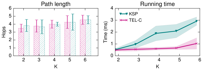
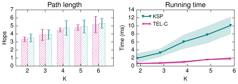
To evaluate the algorithms’ performance, we select some pairs of random sources and destinations in Goodnet and AttMpls networks in terms of the average number of hops and running time for various . The value of varies from 2 and 6 so that in failure scenarios, both algorithms can support up to 6 failed paths. Fig. 8 shows both algorithms explore paths with a similar number of hops. However, TEL-C needs around an order of magnitude less time to find paths when . TEL-C prunes the search space when looking for a path, which significantly reduces the running time.
Quantification of link load: To measure the routing performance of the algorithms, we assess the throughput of each link when every possible link in the network fails. To do so, we take the maximum link utilization over each link failure for all links. We compute the load of individual links as follows.
| (10) |
We compute this measurement for various failure scenarios per pair of sources and destinations. Furthermore, to satisfy this requirement, the network graphs should be 2-connected. Therefore, we report the results for 2-connected network topologies.
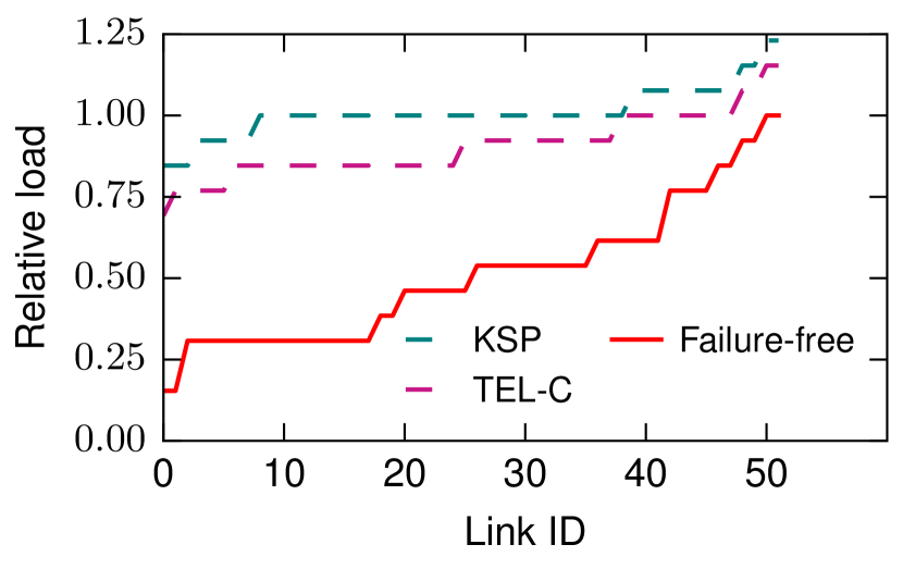
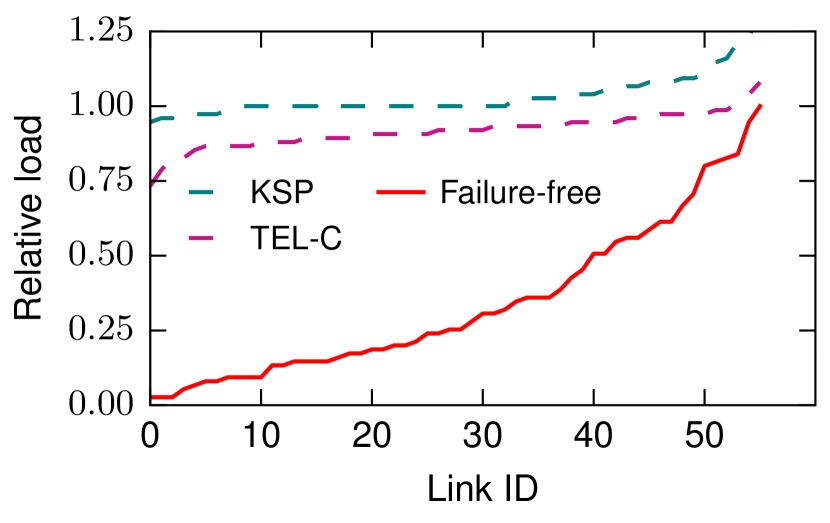
Fig. 9 shows the maximum link load on each link for COST239 [26] and AttMpls networks for failure-free, TEL-C , and KSP algorithms. We replace the Goodnet network with COST239 since the Goodnet topology is not 2-connected, and we cannot run the link load experiment for our scenarios on this network. We order the link IDs in this figure for presentation purposes. The general trend reports that the maximum load of each link increases when the network faces a link failure. For some scenarios, we see that the maximum link load is over 100% with TEL-C and KSP due to the theoretical analysis, i.e., we consider theoretical link utilizations without packet drops. Furthermore, we observe that TEL-C better distributes the load of the network for various failure scenarios.
V-B Performance on Datacenter Topology
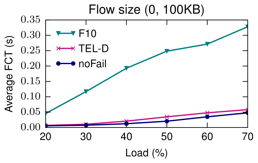
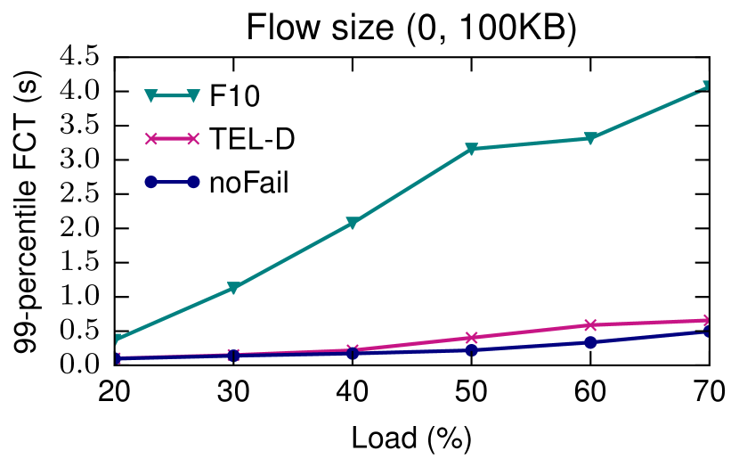
In this part, we compare TEL-D with F10 [12] as the state-of-the-art FRR mechanism. We use leaf-spine topology for comparison with 4 leaf- and spine switches (see Fig. 10). Each link is 100 Mbps. Each leaf switch is connected to 4 servers. Since we are using the Mininet emulator, no additional link delays are applied between switches. We also use the recommendation in [27] to achieve high bandwidth throughput of BMv2.
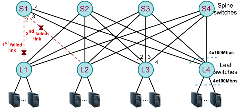

F10 implementation in P4. F10 [12] is one of the state-of-the-art FRR mechanisms that we implement in our datacenter topology. Considering a datacenter topology with a set of spine and leaf switches with links between them, F10 can tolerate up to -1 link failures. It also guarantees loop-free packet forwarding. F10 circularly routes the packets. For example, in our topology in Fig. 10, when links (S1, L1) and (S1, L2) fail, F10 forwards packets through port 3 of S1, which is the next available port in the circular sequence. In this example, the packets of failed links are sent to L3, and then we apply FRR on L3, and the packets reach node S4. From there, they will be forwarded to the right destination.
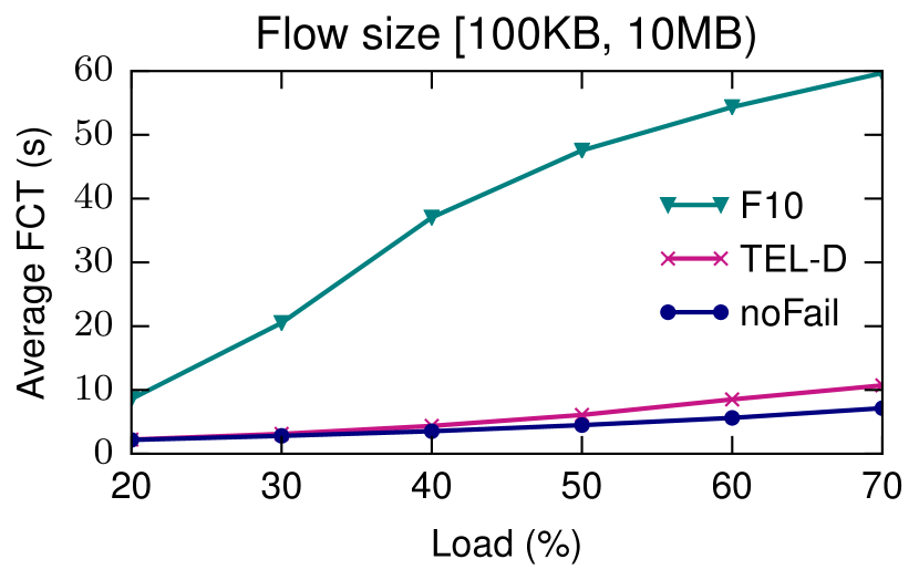
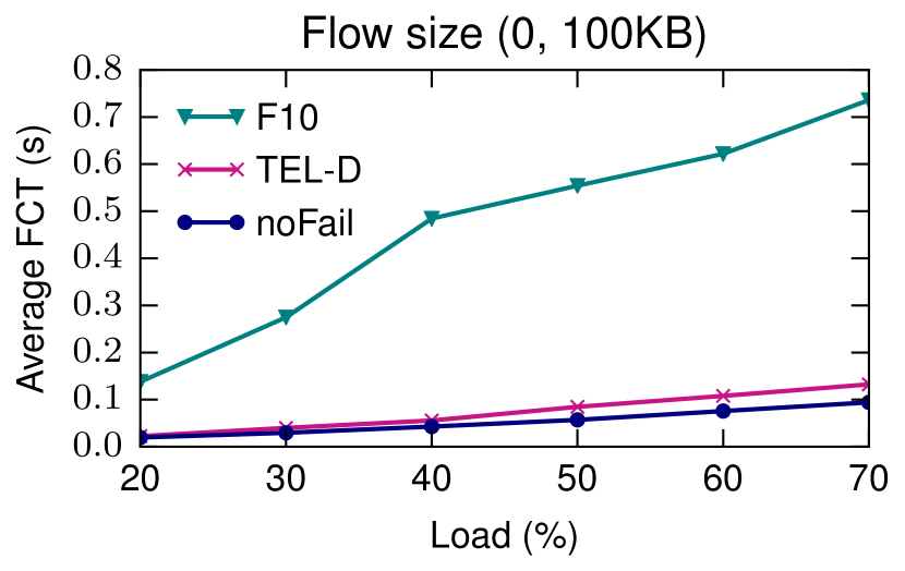
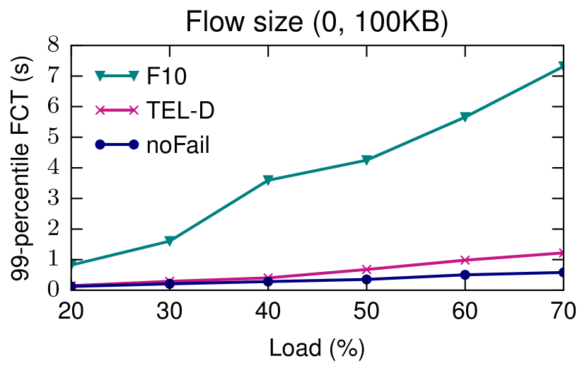
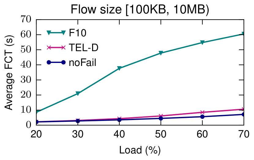
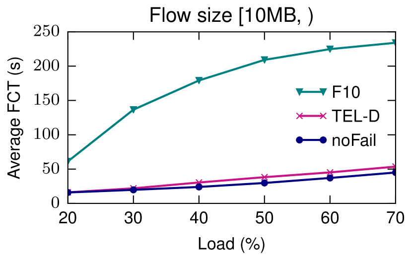
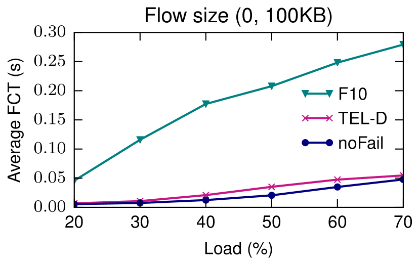
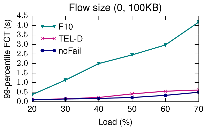
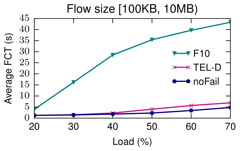
Workloads. We use the two most popular empirically-derived realistic workloads, i.e., web-search [28] and cache-follower [29]. In either workloads, the distributions of the traffic are heavy-tailed. We use the traffic generator in [30] to generate the desired flows in the network according to a Poisson distribution of each workload and the network load. The load varies in the range 20% and 70%. The traffic generator generates different flow sizes as follows. Small flows have the size 100 KB, while mid-size flows are [100 KB, 10 MB). Large flows have the size 10 MB. We send 500 flows, and the results are averaged over 10 different runs.
Routing and congestion control. TEL-D in a datacenter topology relies on ECMP for load balancing which splits traffic using hash-based mechanism. In this mechanism, the incoming traffic to each leaf switch is randomly forwarded to a spine switch. The spine switch forwards the traffic to the destination leaf switch.
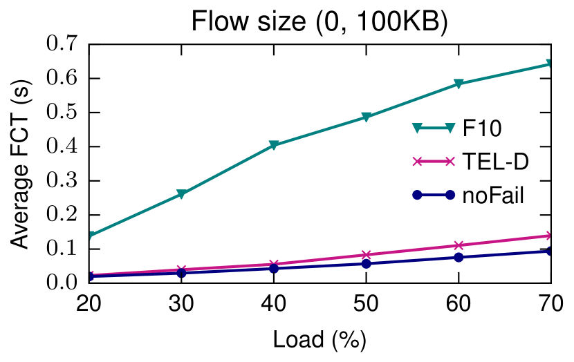
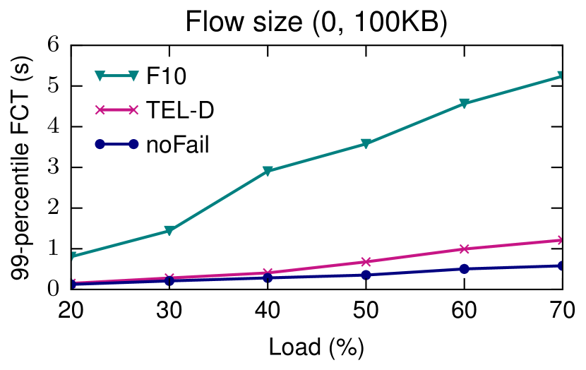
FCT of flows in web-search workload. Focusing on small flows, TEL-D significantly improves the FCT of small flows in the datacenter topology. The results of our experiments for web-search workload were shown in Fig 11. When one link fails in the topology, TEL-D improves the average FCT of small flows between 4.6x to 7.3x compared to F10 in Fig. 11(a). TEL-D improves 4.3x to 7.1x the 99-percentile FCT of small flows when the topology faces a link failure in Fig. 11(b). Focusing on mid-size flows, TEL-D enhances the average FCT between 3.8x to 7.8x compared to F10 in Fig. 11(c). Focusing on large flows, TEL-D improves the average FCT between 3.8x to 6.2x compared to F10 in Fig. 11(d). Similar trends exist for 2 link failures. Interestingly, TEL-D performs very close to noFail case, especially for the scenarios with load 40%, because TEL-D can select one random egress port among the available active ports to steer the traffic.
FCT of flows in cache-follower workload. Focusing on small flows, TEL-D significantly improves the FCT of small flows in the datacenter topology. The results of our experiments for cache-follower workload were shown in Fig. 12. When one link fails in the topology, TEL-D improves the average FCT of small flows between 4x to 11.3x compared to F10 in Fig. 12(a). TEL-D improves 3.6x to 9.7x the 99-percentile FCT of small flows when the topology faces a link failure in Fig. 12(b). Focusing on mid-size flows, TEL-D enhances the average FCT between 3.1x to 12x compared to F10 in Fig. 12(c). Similar to web-search workload results, all the approaches perform similarly in cache-follower workload for 2 link failures. We observe that TEL-D performs very close to noFail case in cache-follower workload. Note that since we run the experiments for 500 flows, we do not have large flows results in Fig. 12.

V-C Performance on WAN topology
In this section, we measure the performance of TEL-C and compare it with DDC [8]. DCC relies on Gafni-Bertsekas’s link reversal algorithms [31] to provide connectivity with two versions, namely, partial and full reversal. We implement full reversal due to its simplicity. DDC keeps the nodes’ state, such as the direction of each link, and we use P4 registers for this purpose. It also keeps a state in the packet header to compare the sequence number of arrived packets. We define a one-bit header field for the sequence number our implementation in P4.
Each network topology has a different number of nodes and ports. Depending on the number of egress ports of each node, we need to keep a different number of bits in the registers. This is not feasible by having a unique P4 code for all nodes. Therefore, we template the P4 code of DDC using Python Jinja2. To provide full connectivity among the nodes, we need to keep one DAG per node since GB’s algorithm is based on DAG. Currently, the P4 language does not support the register of registers and thus, we rely on a single DAG for the evaluation. Note that when running the network topology using Mininet, we load node-specific P4 code on each node.
We use path stretch for comparison, which is defined as the ratio between the length of the path taken by a specific algorithm, i.e., TEL-C and DCC, and the shortest path in the current network. Path stretch is affected by the topology, the choice of source and destination, and the number of failed links [8].
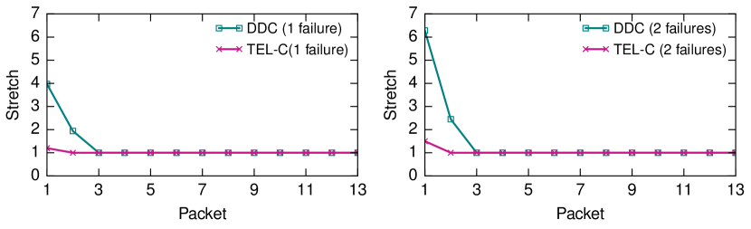
We compare TEL-C and DDC on different topologies such as those of RocketFuel [32] similar to DCC paper, and report some representative results. Fig. 13 shows the 99th percentile stretch of TEL-C and DDC on AS3967 for first 13 packets after link failures. Both algorithms find routes around the failed links after some packets. Generally, by increasing the packets, the stretch decreases to some points, and more link failures result in a higher stretch. TEL-C finds routes for failed links faster than DDC. We also checked the median value of stretch for the 13 packets. Both TEL-C and DDC have a median value of 1 in Fig. 13.
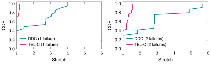
We now check the steady-state stretch of the chosen path. Fig. 14 report the 99th percentile cumulative distribution function (CDF) of stretch for AS3967 with 1 and 2 link failures. Generally, more link failures result in a higher stretch for both algorithms. Since TEL-C leverages the idea of backup paths, the stretch is smaller than those of DDC in both 1 and 2 link failures.
V-D Comparison with MPLS FRR
Multiprotocol Label Switching (MPLS) is widely used to provide FRR in the order of a few 10s of milliseconds delay to repair label-switched path (LSP) tunnels [33]. Similar to TEL-C , the backup LSPs are proactively generated to the desired failures. Therefore, the router detours the traffic from the failed port to an alternative by swapping the packet’s label on the MPLS stack. The packets follow the new paths until reaching the merge point. At this point, the label of the packets swaps from the backup to primary LSP. However, Resource Reservation Protocol-Traffic Engineering (RSVP-TE) signals establishing backup LSPs among routers.
Unlike MPLS FRR, TEL-C does not require a complex signaling mechanism to swap to backup paths. Instead, the controller in the control plane has an overview of the network and provides the required forwarding rules for the backup paths. There is also no need to carry extra labels in the network for the traffic of failed paths.
V-E Comparison with OSFP IP FRR
OSFP IP FRR reduces the reaction time to failure into a few 10s of milliseconds by proactively computing alternative paths. If the primary path fails, then it can rapidly switch to the backup path when the failure is detected. Moreover, OSFP IP FRR requires signal events to its neighbor by using Interior Gateway Protocol (IGP) to recompute the paths for all affected prefixes. Additionally, OSPF Loop-Free Alternate (LFA) FRR can provide a different level of failure protection depending on the network topology.
Unlike OSFP IP FRR, TEL-C does not require a signaling mechanism to swap to backup paths. Instead, the controller in the control plane has an overview of the network and updates the required forwarding rules for the backup paths. Interestingly, TEL-C allows the selection of more factors in path selection.
VI Applying on Practical Applications
Modern networking applications demand ultra-low-latency delay, and link failure can cause many issues. There have been several network issues during recent years leading to wide Internet outages in different continents such as Asia [34]. These kinds of outages result in losing hundreds of thousands of dollars for Google [15], affecting thousands of British Airways airline passengers [35], or disrupting the emergency network [36].
Each small delay in many networking applications can lead to a significant drop in business. For example, Akamai in 2017 reported that every 100 milliseconds of delay have a determinant impact in dropping the customers of online businesses [37]. Other networking applications like voice have around 150 milliseconds of tolerable delay, while for gaming applications, this is about 80 milliseconds [38].
We now explain another practical scenario for big data applications. Distributed stream processing systems like Apache Flink [39] receive data from many resources such as the Internet of Things (IoT) devices, user clicks, and financial transactions. The intermediate results of running a query in such systems should be transferred to the central locations for decision making. The underlying network may fail due to link failure and the highly time-sensitive data require to be rerouted. In such applications, each millisecond of delay is essential for decision making.
In all the above application scenarios, the failure in delivering traffic can lead to the loss of massive revenues, and TEL can be used in any application scenarios that demand low-latency traffic engineering.
VII Related Work
| Reference | Link capacity | Flow conservation | Propagation delay | Link cost | Operation mode | Tools |
| Data Plane | ||||||
| [1] | Decentralized | NS3/Mininet | ||||
| [9] | Centralized | Mininet | ||||
| [40] | Decentralized | |||||
| [41] | Centralized | |||||
| [42] | Centralized | |||||
| [43] | Decenterilized | NS3/Mininet | ||||
| [44] | Distributed | Mininet | ||||
| [45] | Distributed | Mininet | ||||
| [46] | Centralized | Mininet/BMv2 | ||||
| TEL | Decentralized | Mininet/BMv2 | ||||
| Control Plane | ||||||
| [47] | Centralized | |||||
| [48] | Centralized | |||||
| [49] | Centralized | |||||
| [50] | Distributed | |||||
| [51] | Centralized | Mininet/OVS |
In this section, we give a summary of different types of failures that have been proposed on the data plane (see Section VII-A) and the control plane (see Section VII-B). The failure on the L2 switch can be detected in legacy networks that require at least 20 milliseconds [52]. Considering even 20 milliseconds of delay in detecting failure results in losing a considerable amount of traffic while having Tbps of traffic [52, 53].
VII-A Data Plane failure algorithms
In the data plane, we can detect the failures by analyzing the control verification flags of TCP/IP protocol of the metadata of each packet. A summary of FRR solutions in the data plane is reported in [54]. For example, the work in [40] detects the failure by continuously checking the TCP/IP checksum verification and monitors the increment of bit error ratio while decreasing the data rate quality. The work in [41] identifies the failure by validating the throughput plunging and increasing data transmission delay. According to [42], finding a failure on the IP and overlay network is categorized as active and passive solutions. In the former solutions, as reported in [44], they propose a fast failure detection method called BFD that achieves based on the live communication between the neighboring nodes. In the latter solutions, such as [45], the failure state can be detected based on data packet delivery that is given to other nodes. In this case, the neighbors’ nodes can check the packet structure and confirm the links and required operations. However, this type of failure detection requires receiving data flow regularly from the neighbor nodes. Also, the authors in [43] design a DAG-based algorithm to minimize the number of entries required on the SDN switches. Besides, it decreases the local restoration latency for a failed node/link such that the SDN controller will not be affected. This solution performs only based on the standard features of OpenFlow and avoids inconsistent forwarding tables during updates. The authors in [46] design SPIDER, a new failure recovery approach that provides a fully programmable abstraction and re-routing policies in SDN. SPIDER aims to minimize the recovery delay and guarantees the failover even when the controller is not reachable. Besides, the work [55] implements a fast failover algorithm in OpenFlow to re-route traffics based on the gathered information from packet headers. This method monitors the packet movement on various routes. It analyzes them based on multiple traversal network graph mechanisms, such as depth-first search and breath-first search. The routing is carried out using failure-carrying packets [56] algorithm. TEL-D significantly improves the FCT of flows compared to the state-of-the-art FRR mechanisms.
VII-B Control Plane failure algorithms
Failure faces several routing and data steering issues in SDN, minimizing packet losses and increasing transmission delay. Applying a failure detection mechanism in the control plane leads to having resilient routing in an Ethernet network. In [47], the authors designed a tool based on Spanning Tree Protocol (STP) on the IEEE 802.1D to avoid forwarding loops while providing necessary restoration capabilities. STP also guarantees to establish a unique path between any two nodes. However, it is not equipped to cover failure recovery, and its convergence speed is prolonged up to 50 seconds [48], which is not an efficient method for real-time applications in large networks.
Some failure recovery solutions are based on MPLS, which can be managed through a data plane. For example, the paper [49] utilizes label switching routers to handle the steering packets along with switches by labeling the packet header. They design a label distribution protocol to manage the labeled packets and understand the failure that may happen in the network. Also, the solution’s extension is tested and validated on the label distribution protocol reported in [50]. Recently, in [51], the authors design two FRR algorithms managed through a control plane on MPLS. These algorithms can rapidly index the shortest recovery paths and the shortest guaranteed-cost path method to decrease the recovery path’s delay cost in an SDN. Unlike the above techniques, TEL-C can satisfy the max-min fair allocation. Table II presents a comparison of approaches. The goal of the first category is to present the features of solutions applying in the data plane while the second category does the same for the control plane. Also, the symbol "" indicates that the approach supports the property; Otherwise, we used "". Besides, we classify the operational mode into centralized, decentralized, and distributed.
VIII Conclusion
This paper presents two FRR mechanisms for programmable data plane to steer the traffic with a low failover latency in the failure scenarios. We propose one proactive and one reactive FRR mechanisms. The first one, TEL-C, calculates the primary and backup paths in the control plane satisfying max-min fair allocation and insert the forwarding rules into the network devices. When failure occurs, the network device can reroute the traffic according to the backup paths. The second one, TEL-D, reroutes the traffic in the data plane, making it suitable for self-driving programmable networks. In the future, we plan to extend the TEL-C by considering sophisticated traffic policies like priority-based traffic engineering. Also, we plan to extend the TEL-D for load balancing scenarios. Furthermore, we plan to extend our learning algorithm with many robust ones such as the max-logit and b-logit [57].
Acknowledgment
This work was funded by the German Ministry for Education and Research as BIFOLD - Berlin Institute for the Foundations of Learning and Data (ref. 01IS18025A and 01IS18037A). Mohammad Shojafar is supported by Marie Curie Global Fellowship funded by European Commission with grant agreement MSCA-IF-GF-839255.
References
- [1] M. Chiesa, R. Sedar, G. Antichi, M. Borokhovich, A. Kamisiundefinedski, G. Nikolaidis, and S. Schmid, “Purr: A primitive for reconfigurable fast reroute: Hope for the best and program for the worst,” in Proceedings of the 15th International Conference on Emerging Networking Experiments And Technologies, ser. CoNEXT ’19, 2019, p. 1–14.
- [2] P. Bosshart, D. Daly, G. Gibb, M. Izzard, N. McKeown, J. Rexford, C. Schlesinger, D. Talayco, A. Vahdat, G. Varghese et al., “P4: Programming protocol-independent packet processors,” ACM SIGCOMM Computer Communication Review, vol. 44, no. 3, pp. 87–95, 2014.
- [3] R. Ben Basat, S. Ramanathan, Y. Li, G. Antichi, M. Yu, and M. Mitzenmacher, “Pint: Probabilistic in-band network telemetry,” in Proceedings of the Annual Conference of the ACM Special Interest Group on Data Communication on the Applications, Technologies, Architectures, and Protocols for Computer Communication, ser. SIGCOMM ’20, 2020, p. 662–680.
- [4] N. Katta, M. Hira, C. Kim, A. Sivaraman, and J. Rexford, “Hula: Scalable load balancing using programmable data planes,” in Proceedings of the Symposium on SDN Research, ser. SOSR ’16, 2016.
- [5] L. Jose, S. Ibanez, M. Alizadeh, and N. McKeown, “A distributed algorithm to calculate max-min fair rates without per-flow state,” Proceedings of the ACM on Measurement and Analysis of Computing Systems, vol. 3, no. 2, pp. 1–42, 2019.
- [6] G. Li, Y. Qian, and Y. R. Yang, “On max-min fair allocation for multi-source transmission,” SIGCOMM Comput. Commun. Rev., vol. 48, no. 5, p. 2–8, Jan. 2019.
- [7] A. Markopoulou, G. Iannaccone, S. Bhattacharyya, C.-N. Chuah, Y. Ganjali, and C. Diot, “Characterization of failures in an operational ip backbone network,” IEEE/ACM transactions on networking, vol. 16, no. 4, pp. 749–762, 2008.
- [8] J. Liu, A. Panda, A. Singla, B. Godfrey, M. Schapira, and S. Shenker, “Ensuring connectivity via data plane mechanisms,” in Presented as part of the 10th USENIX Symposium on Networked Systems Design and Implementation (NSDI 13), 2013, pp. 113–126.
- [9] T. Qu, R. Joshi, M. C. Chan, B. Leong, D. Guo, and Z. Liu, “Sqr: In-network packet loss recovery from link failures for highly reliable datacenter networks,” in 2019 IEEE 27th International Conference on Network Protocols (ICNP). IEEE, 2019, pp. 1–12.
- [10] T. Holterbach, E. C. Molero, M. Apostolaki, A. Dainotti, S. Vissicchio, and L. Vanbever, “Blink: Fast connectivity recovery entirely in the data plane,” in 16th USENIX Symposium on Networked Systems Design and Implementation (NSDI 19), 2019, pp. 161–176.
- [11] K. Qian, S. Ma, M. Miao, J. Lu, T. Zhang, P. Wang, C. Sun, and F. Ren, “Flexgate: High-performance heterogeneous gateway in data centers,” in Proceedings of the 3rd Asia-Pacific Workshop on Networking 2019, 2019, pp. 36–42.
- [12] V. Liu, D. Halperin, A. Krishnamurthy, and T. Anderson, “F10: A fault-tolerant engineered network,” in 10th USENIX Symposium on Networked Systems Design and Implementation (NSDI 13), Lombard, IL, Apr. 2013, pp. 399–412.
- [13] Zheng Wang and J. Crowcroft, “Quality-of-service routing for supporting multimedia applications,” IEEE Journal on Selected Areas in Communications, vol. 14, no. 7, pp. 1228–1234, Sep. 1996.
- [14] G. Smaragdakis, N. Laoutaris, K. Oikonomou, I. Stavrakakis, and A. Bestavros, “Distributed server migration for scalable internet service deployment,” IEEE/ACM Trans. Netw., vol. 22, no. 3, p. 917–930, Jun. 2014.
- [15] D. Tweney, “5-minute outage costs google $545,000 in revenue,” 2013, http://venturebeat.com/2013/08/16/3-minute-outage-costs-google-545000-in-revenue/.
- [16] A. B. pricing, “Data transferred out of azure data centers,” 2021, https://azure.microsoft.com/en-us/pricing/details/bandwidth/.
- [17] E. Grossman, C. Gunther, P. Thubert, P. Wetterwald, J. Raymond, J. Korhonen, Y. Kaneko, S. Das, Y. Zha, B. Varga et al., “Deterministic networking use cases,” RFC 8578, Internet Engineering Task Force (IETF), 2019.
- [18] J.-Y. Le Boudec, “Rate adaptation, congestion control and fairness: A tutorial.”
- [19] E. Crawley, R. Nair, B. Rajagopalan, and H. Sandick, “A framework for qos-based routing in the internet,” 1998.
- [20] M. R. M. Meybodi and M. R. Meybodi, “Extended distributed learning automata,” Applied Intelligence, vol. 41, no. 3, pp. 923–940, 2014.
- [21] K. S. Narendra and M. A. Thathachar, Learning automata: an introduction. Courier corporation, 2012.
- [22] P4 Language Consortium, “Behavioral model (bmv2),” 2020, https://github.com/p4lang/behavioral-model.
- [23] ——, “P4 language specification,” 2020, https://p4.org/p4-spec/docs/P4-16-v1.2.0.pdf.
- [24] B. Lantz, B. Heller, and N. McKeown, “A network in a laptop: rapid prototyping for software-defined networks,” in Proceedings of the 9th ACM SIGCOMM Workshop on Hot Topics in Networks, 2010, pp. 1–6.
- [25] “TEL source code,” 2020, https://gitlab.inet.tu-berlin.de/habib/TEL.
- [26] M. O’Mahony, “Results from the cost 239 project. ultra-high capacity optical transmission networks,” in Proceedings of European Conference on Optical Communication, vol. 2, 1996, pp. 11–18 vol.2.
- [27] P4 Language Consortium, “Performance of bmv2,” 2020, https://github.com/p4lang/behavioral-model/blob/main/docs/performance.md.
- [28] M. Alizadeh, A. Greenberg, D. A. Maltz, J. Padhye, P. Patel, B. Prabhakar, S. Sengupta, and M. Sridharan, “Data center tcp (dctcp),” in Proceedings of the ACM SIGCOMM 2010 conference, 2010, pp. 63–74.
- [29] A. Roy, H. Zeng, J. Bagga, G. Porter, and A. C. Snoeren, “Inside the social network’s (datacenter) network,” in Proceedings of the 2015 ACM Conference on Special Interest Group on Data Communication, ser. SIGCOMM ’15, 2015, p. 123–137.
- [30] W. Bai, L. Chen, K. Chen, and H. Wu, “Enabling ECN in multi-service multi-queue data centers,” in 13th USENIX Symposium on Networked Systems Design and Implementation (NSDI 16), 2016, pp. 537–549.
- [31] E. Gafni and D. Bertsekas, “Distributed algorithms for generating loop-free routes in networks with frequently changing topology,” IEEE Transactions on Communications, vol. 29, no. 1, pp. 11–18, 1981.
- [32] N. Spring, R. Mahajan, and D. Wetherall, “Measuring isp topologies with rocketfuel,” SIGCOMM Comput. Commun. Rev., vol. 32, no. 4, p. 133–145, Aug. 2002.
- [33] P. Pan, G. Swallow, A. Atlas et al., “Fast reroute extensions to rsvp-te for lsp tunnels,” 2005.
- [34] R. Chirgwin, “Google routing blunder sent japan’s internet dark on friday,” 2017, https://www.theregister.co.uk/2017/08/27/google_routing_blunder_sent_japans_internet_dark/.
- [35] G. Corfield, “British airways’ latest total inability to support upwardness of planes caused by amadeus system outage,” 2017, https://www.theregister.co.uk/2018/07/19/amadeus_british_airways_outage_load_sheet/.
- [36] C. Gibbs, “Att’s 911 outage result of mistakes made by att, fcc’s pai says,” 2017, https://www.fiercewireless.com/wireless/at-t-s-911-outage-result-mistakes-made-by-at-t-fcc-s-pai-says.
- [37] J. Young and T. Barth, “Web performance analytics show even 100-millisecond delays can impact customer engagement and online revenue,” 2017, Akamai Online Retail Performance Report.
- [38] J. Saldan, “Delay limits for real-time services,” 2016, IETF Drafft.
- [39] “Apache Flink,” 2020, https://flink.apache.org/.
- [40] ITU-TEC, “G.975: Forward error correction for submarine systems,” International Telecommunication Union, Tech. Rep., 2000.
- [41] P. Cholda and A. Jajszczyk, “Recovery and its quality in multilayer networks,” Journal of Lightwave Technology, vol. 28, no. 4, pp. 372–389, 2009.
- [42] S. Q. Zhuang, D. Geels, I. Stoica, and R. H. Katz, “On failure detection algorithms in overlay networks,” in Proceedings IEEE 24th Annual Joint Conference of the IEEE Computer and Communications Societies., vol. 3. IEEE, 2005, pp. 2112–2123.
- [43] S. Avallone and U. Ashraf, “A dag-based forwarding paradigm for large scale software defined networks,” IEEE Transactions on Network and Service Management, vol. 17, no. 1, pp. 577–591, 2020.
- [44] D. Katz, D. Ward et al., “Bidirectional forwarding detection (bfd),” 2010.
- [45] R. Steinert and D. Gillblad, “Towards distributed and adaptive detection and localisation of network faults,” in 2010 Sixth Advanced International Conference on Telecommunications. IEEE, 2010, pp. 384–389.
- [46] C. Cascone, D. Sanvito, L. Pollini, A. Capone, and B. Sanso, “Fast failure detection and recovery in sdn with stateful data plane,” International Journal of Network Management, vol. 27, no. 2, p. e1957, 2017.
- [47] IEEE Std 802.1D-2004 (Revision of IEEE Std 802.1D-1998), “Ieee standard for local and metropolitan area networks: Media access control (mac) bridges,” 2020, https://standards.ieee.org/standard/802_1D-2004.html.
- [48] K. Elmeleegy, A. L. Cox, and T. E. Ng, “On count-to-infinity induced forwarding loops ethernet networks,” in Proceedings IEEE INFOCOM 2006. 25TH IEEE International Conference on Computer Communications. IEEE, 2006, pp. 1–13.
- [49] E. Rosen, A. Viswanathan, R. Callon et al., “Multiprotocol label switching architecture,” 2001.
- [50] L. Andersson, I. Minei, and B. Thomas, “Ldp specification,” 2007, https://tools.ietf.org/html/rfc5036.
- [51] K. Qiu, J. Zhao, X. Wang, X. Fu, and S. Secci, “Efficient recovery path computation for fast reroute in large-scale software-defined networks,” IEEE Journal on Selected Areas in Communications, vol. 37, no. 8, pp. 1755–1768, 2019.
- [52] “Common Interval Support in Bidirectional Forwarding Detection,” 2020, https://tools.ietf.org/html/rfc7419.
- [53] “Bidirectional Forwarding Detection (BFD) for Multipoint Networks,” 2020, https://tools.ietf.org/html/rfc8562.
- [54] M. Chiesa, A. Kamisiński, J. Rak, G. Rétvári, and S. Schmid, “Fast recovery mechanisms in the data plane,” 2020.
- [55] M. Borokhovich, L. Schiff, and S. Schmid, “Provable data plane connectivity with local fast failover: Introducing openflow graph algorithms,” in Proceedings of the Third Workshop on Hot Topics in Software Defined Networking, ser. HotSDN ’14. Association for Computing Machinery, 2014, p. 121–126.
- [56] K. Lakshminarayanan, M. Caesar, M. Rangan, T. Anderson, S. Shenker, and I. Stoica, “Achieving convergence-free routing using failure-carrying packets,” SIGCOMM Comput. Commun. Rev., vol. 37, no. 4, p. 241–252, Aug. 2007.
- [57] G. Fragkos, E. E. Tsiropoulou, and S. Papavassiliou, “Artificial intelligence enabled distributed edge computing for internet of things applications,” in 2020 16th International Conference on Distributed Computing in Sensor Systems (DCOSS), 2020, pp. 450–457.
![[Uncaptioned image]](/html/2009.13640/assets/HMostafaei.jpg) |
Habib Mostafaei is currently a postdoctoral researcher at the Internet Network Architectures (INET) of Technische Universität Berlin. He received a Ph.D. in Computer Science and Engineering from Roma Tre University in 2019. He currently works as a senior researcher in the BIFOLD-BBDC project on networking problems for big data analytics. In 2018, he spent eight months as a visiting researcher at the University of Tuebingen. Before the Ph.D. education, he worked as a full-time faculty member at the Computer Engineering Department of Azad University (2009-2015). Currently, his main research fields include networked systems, network management, and distributed systems. For additional information: https://inet.tu-berlin.de/~habib |
![[Uncaptioned image]](/html/2009.13640/assets/MShojafar.jpeg) |
Mohammad Shojafar (M’17-SM’19) is a Senior Lecturer (Associate Professor) in the network security and an Intel Innovator, and a Marie Curie Alumni, working in the 5G Innovation Centre (5GIC) at the University of Surrey, UK. Before joining 5GIC, he was a senior researcher and a Marie Curie Fellow in the SPRITZ Security and Privacy Research group at the University of Padua, Italy. Also, he was a CNIT senior researcher at the University of Rome Tor Vergata contributed to the 5G PPP European H2020 “SUPERFLUIDITY” project. Dr. Mohammad was a PI of the PRISENODE project, a 275k euro Horizon 2020 Marie Curie global fellowship project in the areas of Fog/Cloud security collaborating at the University of Padua. He also was a PI on an Italian SDN security and privacy project (60k euro) supported by the University of Padua in 2018 and a Co-PI on an Ecuadorian-British project on IoT and Industry 4.0 resource allocation (20k dollars) in 2020. He was contributed to some Italian projects in telecommunications like GAUChO, SAMMClouds, and SC2. He received his Ph.D. degree from Sapienza University of Rome, Rome, Italy, in 2016 with an “Excellent” degree. He is an Associate Editor in IEEE Transactions on Consumer Electronics, IEEE Systems Journal and IET Communications. For additional information: https://www.surrey.ac.uk/people/mohammad-shojafar |
![[Uncaptioned image]](/html/2009.13640/assets/MConti.png) |
Mauro Conti is Full Professor at the University of Padua, Italy. He is also affiliated with TU Delft and University of Washington, Seattle. He obtained his Ph.D. from Sapienza University of Rome, Italy, in 2009. After his Ph.D., he was a Post-Doc Researcher at Vrije Universiteit Amsterdam, The Netherlands. In 2011 he joined as Assistant Professor the University of Padua, where he became Associate Professor in 2015, and Full Professor in 2018. He has been Visiting Researcher at GMU, UCLA, UCI, TU Darmstadt, UF, and FIU. He has been awarded with a Marie Curie Fellowship (2012) by the European Commission, and with a Fellowship by the German DAAD (2013). His research is also funded by companies, including Cisco, Intel, and Huawei. His main research interest is in the area of Security and Privacy. In this area, he published more than 350 papers in topmost international peer-reviewed journals and conferences. He is Area Editor-in-Chief for IEEE Communications Surveys & Tutorials, and Associate Editor for several journals, including IEEE Communications Surveys & Tutorials, IEEE Transactions on Dependable and Secure Computing, IEEE Transactions on Information Forensics and Security, and IEEE Transactions on Network and Service Management. He was Program Chair for TRUST 2015, ICISS 2016, WiSec 2017, ACNS 2020, and General Chair for SecureComm 2012, SACMAT 2013, CANS 2021, and ACNS 2022. He is Senior Member of the IEEE and ACM. He is member of the Blockchain Expert Panel of the Italian Government. He is Fellow of the Young Academy of Europe. For additional information: http://www.math.unipd.it/~conti/. |