Charge-Spin Interconversion in Epitaxial Pt Probed by Spin-Orbit Torques in a Magnetic Insulator
Abstract
We measure spin-orbit torques (SOTs) in a unique model system of all-epitaxial ferrite/Pt bilayers to gain insights into charge-spin interconversion in Pt. With negligible electronic conduction in the insulating ferrite, the crystalline Pt film acts as the sole source of charge-to-spin conversion. A small field-like SOT independent of Pt thickness suggests a weak Rashba-Edelstein effect at the ferrite/Pt interface. By contrast, we observe a sizable damping-like SOT that depends on the Pt thickness, from which we deduce the dominance of an extrinsic spin-Hall effect (skew scattering) and Dyakonov-Perel spin relaxation in the crystalline Pt film. Furthermore, our results point to a large internal spin-Hall ratio of 0.8 in epitaxial Pt. Our experimental work takes an essential step towards understanding the mechanisms of charge-spin interconversion and SOTs in Pt-based heterostructures, which are crucial for power-efficient spintronic devices.
I Introduction
Spin-orbit torques (SOTs) Sinova et al. (2015); Ramaswamy et al. (2018) have been recognized as a viable means to manipulate magnetization in thin-film heterostructures. A prototypical SOT-driven medium consists of a ferro(ferri)magnetic metal (FM) interfaced with a nonmagnetic heavy metal (HM) with strong spin-orbit coupling (e.g., Pt). In a conventional picture of SOTs in such a bilayer, an in-plane charge current through the HM (or its surface) generates non–equilibrium spin accumulation via the spin-Hall effect (or Rashba-Edelstein effect) Sinova et al. (2015); Ramaswamy et al. (2018); Hoffmann (2013); Manchon et al. (2015). This charge-to-spin conversion then results in SOTs Sinova et al. (2015); Ramaswamy et al. (2018); Brataas and Hals (2014); Haney et al. (2013), typically classified into (1) a “damping-like” torque that either enhances or counteracts damping in the magnetic layer and (2) a “field-like” torque that acts similarly to a torque from an external magnetic field.
Although SOTs are often attributed to charge-to-spin conversion effects in the HM, recent studies point to other effects that impact SOTs in metallic FM/HM bilayers Taniguchi et al. (2015); Amin and Stiles (2016); Amin et al. (2018); Humphries et al. (2017); Baek et al. (2018); Gibbons et al. (2018); Iihama et al. (2018); Safranski et al. (2019); Wang et al. (2019); Wu et al. (2019); Zhou et al. (2015); Garello et al. (2013); Pai et al. (2015); Rojas-Sánchez et al. (2014); Chen and Zhang (2015); Dolui and Nikolić (2017); Berger et al. (2018); Zhu et al. (2019a); Zhang et al. (2015a); Caminale et al. (2016). For example, current shunted through the FM can generate additional SOTs through spin-dependent scattering within the FM or across the FM/HM interface Taniguchi et al. (2015); Amin and Stiles (2016); Amin et al. (2018, 2019); Humphries et al. (2017); Baek et al. (2018); Gibbons et al. (2018); Iihama et al. (2018); Safranski et al. (2019); Wang et al. (2019); Wu et al. (2019). Roughness at the interfaces of FM/HM bilayers, which are typically disordered (i.e., polycrystalline or amorphous), may also contribute to SOTs Zhou et al. (2015); Garello et al. (2013); Pai et al. (2015). Even with atomically sharp FM/HM interfaces, SOTs may be intrinsically impacted by spin-memory loss Rojas-Sánchez et al. (2014); Chen and Zhang (2015); Dolui and Nikolić (2017); Berger et al. (2018); Zhu et al. (2019a) and proximity-induced magnetism Zhang et al. (2015a); Caminale et al. (2016) due to orbital hybridization.
These possible complications in FM/HM bilayers make it difficult to elucidate the fundamental mechanisms of SOTs and, more generally, the underlying charge-to-spin conversion phenomena. These factors also impede reconciling the wide spread of reported spin transport parameters – particularly for the often-used HM of Pt, with its spin diffusion length in the range 1-10 nm and its spin-Hall ratio 0.01-1 Liu et al. (2011a); Morota et al. (2011); Kondou et al. (2012); Zhang et al. (2013); Niimi et al. (2013); Rojas-Sánchez et al. (2014); Wang et al. (2014); Isasa et al. (2015); Boone et al. (2015); Zhang et al. (2015b); Sagasta et al. (2016); Nguyen et al. (2016); Stamm et al. (2017); Berger et al. (2018); Tao et al. (2018); Swindells et al. (2019); Zhu et al. (2019b); Dai et al. (2019).
Here, we demonstrate a clean ferrimagnetic-insulator/heavy-metal (FI/HM) model system where SOTs originate solely in the HM layer, permitting a simpler analysis of charge-to-spin conversion mechanisms. Specifically, we investigate SOTs at room temperature in FI/HM bilayers where the FI is an epitaxial spinel ferrite film of MgAl0.5Fe1.5O4 (MAFO) Emori et al. (2018a) and the HM is an epitaxial film of Pt, whose high crystallinity is enabled by its excellent lattice match to the spinel Lee et al. (2019). The insulating nature of MAFO removes all complications from electronic spin transport in the magnetic layer Taniguchi et al. (2015); Amin and Stiles (2016); Amin et al. (2018, 2019); Humphries et al. (2017); Baek et al. (2018); Gibbons et al. (2018); Iihama et al. (2018); Safranski et al. (2019); Wang et al. (2019); Wu et al. (2019), and the Pt layer with a sharp crystalline interface minimizes roughness-induced mechanisms Zhou et al. (2015); Garello et al. (2013); Pai et al. (2015). Spin-memory loss and proximity-induced magnetism are also expected to be significantly weaker in FI/HM Emori et al. (2018b); Valvidares et al. (2016); Gray et al. (2018a); Riddiford et al. (2019) compared to FM/HM Rojas-Sánchez et al. (2014); Chen and Zhang (2015); Dolui and Nikolić (2017); Berger et al. (2018); Zhu et al. (2019a); Caminale et al. (2016); Zhang et al. (2015a) due to weaker interfacial hybridization Dolui and Nikolić (2017).
We leverage the low damping of MAFO Emori et al. (2018a) to quantify both the damping-like and field-like SOTs in a straightforward manner through dc-biased spin-torque ferromagnetic resonance (ST-FMR) Liu et al. (2011b); Kasai et al. (2014); Nan et al. (2015); Tiwari et al. (2017); Kim et al. (2018). We observe a large damping-like SOT due to the spin-Hall effect in the bulk of Pt Hoffmann (2013); Sinova et al. (2015), along with an order-of-magnitude smaller field-like SOT attributed to the interfacial Rashba-Edelstein effect Manchon et al. (2015); Gambardella and Miron (2011). Modeling the Pt thickness dependence of the damping-like SOT and spin-pumping damping indicates that the skew scattering Hoffmann (2013); Sinova et al. (2015); Sagasta et al. (2016); Karnad et al. (2018) and Dyakonov-Perel Ryu et al. (2016); Freeman et al. (2018) mechanisms primarily govern charge-to-spin conversion and spin relaxation, respectively, in epitaxial Pt. This combination of mechanisms is distinct from the intrinsic spin-Hall effect and Elliott-Yafet spin relaxation often found in Pt-based systems Nguyen et al. (2016); Stamm et al. (2017); Swindells et al. (2019); Zhu et al. (2019b); Du et al. (2020). Our modeling results point to a large internal spin-Hall ratio of 0.8 in Pt, while a small spin-mixing conductance of 1 m-2 primarily limits the efficiency of the damping-like SOT in the MAFO/Pt bilayer. Our work demonstrates a unique material system and experimental approach to uncover the mechanisms of charge-spin interconversion in Pt, with minimal spurious influence from the adjacent magnetic layer.
II Film growth and structural properties
MAFO is a low-damping FI with a Curie temperature of 400 K, which can be grown epitaxially on spinel MgAl2O4 (MAO) substrates Emori et al. (2018a). We first deposit epitaxial MAFO films on (001)-oriented single-crystal MAO by pulsed laser ablation. A sintered ceramic target of stoichiometric MgAl0.5Fe1.5O4 is ablated in 10 mTorr of O2 at a fluence of 2 J/cm2, repetition rate of 1 Hz, target-to-substrate separation of 75 mm, and substrate temperature of 450 ∘C. No post-annealing at a higher temperature is performed. All MAFO films are grown to be 13 nm thick, which is within the optimal thickness range that ensures coherently strained growth and low Gilbert damping Emori et al. (2018a); Wisser et al. (2019a). Broadband ferromagnetic resonance (FMR) measurements confirm a Gilbert damping parameter of for these MAFO films, similar to prior reports Emori et al. (2018a); Wisser et al. (2019a); Riddiford et al. (2019). Then, 3-19 nm thick Pt layers are sputtered onto the MAFO films in 3 mTorr of Ar at room temperature. To avoid surface damage, we used a low dc power of 15 W.
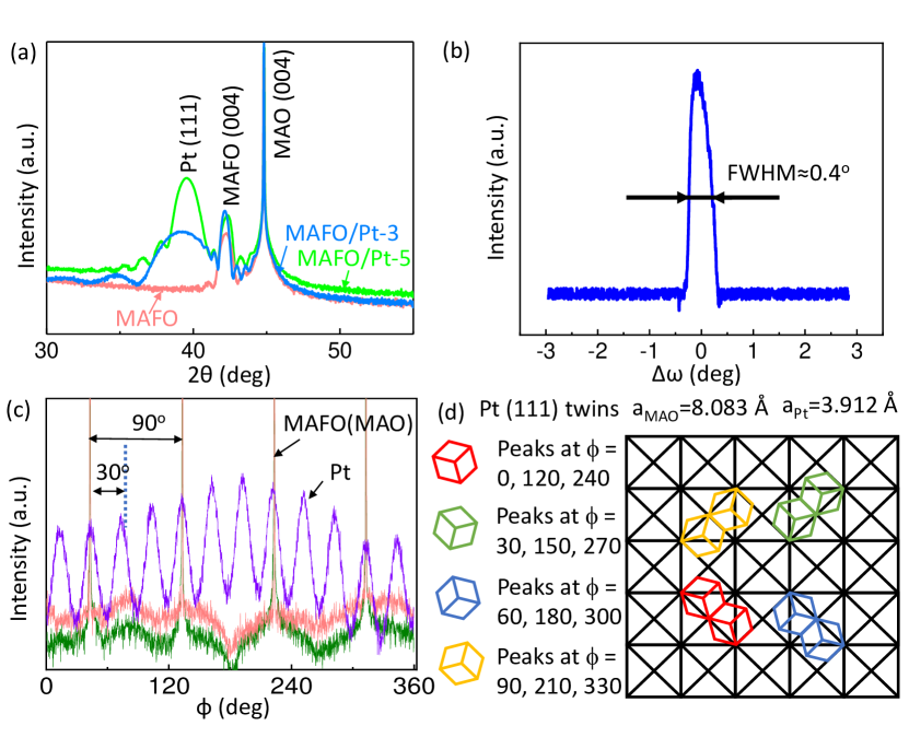
X–ray diffraction (XRD) measurements indicate epitaxy and high crystallinity of our MAFO/Pt samples. Figure 1(a) shows symmetrical scans for MAFO/Pt and MAFO samples. Strong Pt(111) and MAFO(004) Bragg peaks indicate a high degree of out-of-plane epitaxy. The visible Laue oscillations around the Pt(111) peak for the MAFO/Pt bilayers further indicate high structural quality of the Pt film. The degree of crystallinity of the Pt layer is determined by performing a rocking curve measurement around the Pt(111) peak. The narrow rocking curve width of 0.4∘ (Fig. 1(b)) indicates a uniform out-of-plane orientation of Pt crystals with an only small mosaic spread.
The in-plane orientation of MAFO/Pt is investigated by measuring asymmetrical (113) Bragg peaks for Pt, MAFO, and MAO layers. The MAFO layer is fully coherently strained to the MAO substrate as indicated in the previous study Emori et al. (2018a). As can be seen from Fig. 1(c), the MAFO layer and MAO substrate exhibit four-fold symmetry that is expected from their cubic structures. The Pt(113) peak exhibits twelve maxima indicating a rather complex epitaxial relationship. Careful analysis of the Pt in-plane orientation on MAFO reveals a twinning pattern of the Pt domains, which is presented in Fig. 1(d). One can distinguish four Pt domains that match MAFO epitaxially and produce in total twelve Pt(113) peaks as shown in Fig. 1(c).
It should be noted that the epitaxial growth of Pt on MAFO is in contrast to polycrystalline or amorphous Pt on iron garnets Wang et al. (2014); Lustikova et al. (2014); Chang et al. (2017). Further, X-ray reflectivity indicates a small roughness of 0.2 nm at the MAFO/Pt interface. Our structural characterization thus confirms that MAFO/Pt is a high-quality model system with a highly crystalline structure and sharp interface.
III Results and Discussion
III.1 DC-Biased Spin-Torque Ferromagnetic Resonance
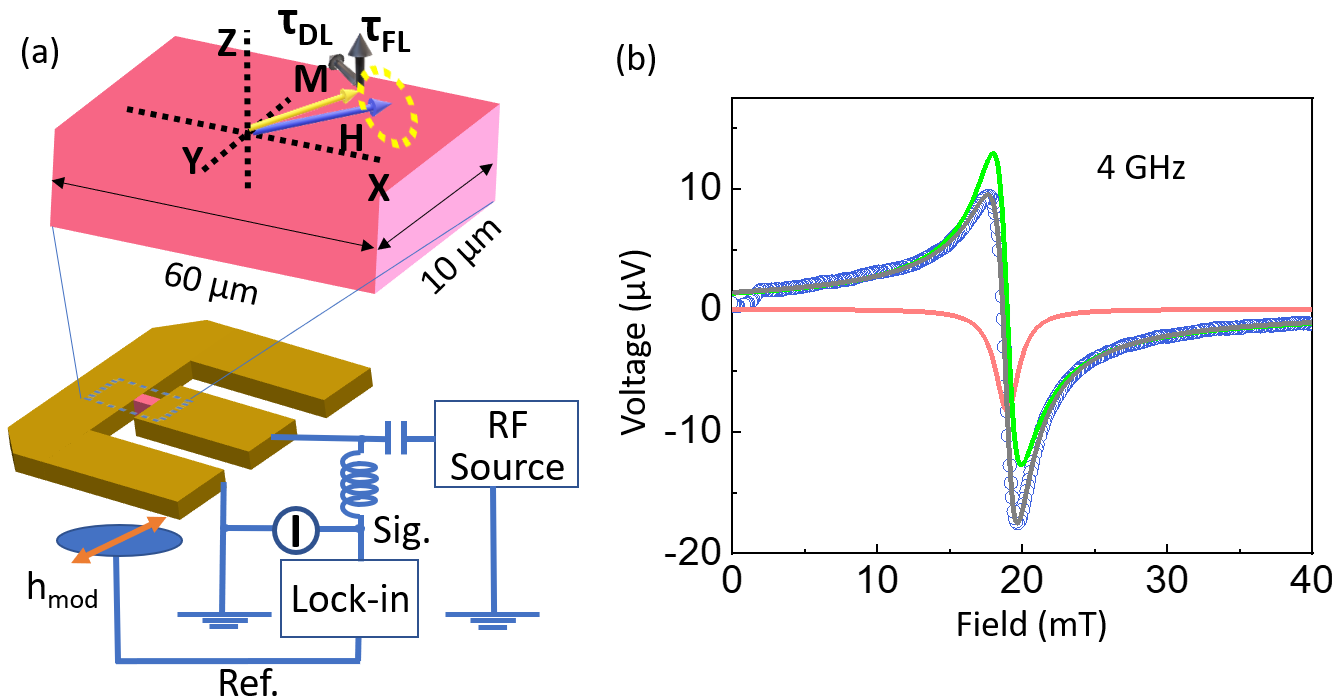
The MAFO/Pt bilayers are lithographically patterned and ion-milled to 60 m 10 m strips with the edges parallel to the in-plane axes of MAFO. They are then contacted by Ti (5 nm)/Au (120 nm) ground-signal-ground electrodes to allow input of a microwave current for our ST-FMR measurements at room temperature, as illustrated in Fig. 2(a). We have verified that the magnetic properties of MAFO/Pt are unchanged by the lithographic patterning process (see Appendix A).
The microwave current in Pt induces SOTs and a classical Oersted field torque on the magnetization in the MAFO layer. ST-FMR spectra are obtained from the rectified voltage due to magnetoresistance and spin-pumping signals Schreier et al. (2015); Sklenar et al. (2015) with field modulation Gonçalves et al. (2013). Each integrated ST-FMR spectrum (e.g., Fig. 2(c)) can be fit with a superposition of symmetric and antisymmetric Lorentzians to extract the half-width-at-half-maximum linewidth and resonance field .
We use an additional dc bias current to directly extract the damping-like and field-like SOTs Liu et al. (2011b); Kasai et al. (2014); Nan et al. (2015); Tiwari et al. (2017); Kim et al. (2018) in MAFO/Pt. This dc bias approach circumvents ambiguities of the oft-used symmetric/antisymmetric Lorentzian ST-FMR lineshape analysis (e.g., where the symmetric Lorentzian can contain voltage signals from spin pumping and thermoelectric effects Schreier et al. (2015); Sklenar et al. (2015); Okada et al. (2019); Schultheiss et al. (2012)) and instead probes both SOTs in a direct manner. In particular, the dc damping-like SOT modifies the effective damping ( linewidth ) linearly with the dc bias current density ; the dc field-like torque shifts the resonance field linearly with . Since all of the current flows in the Pt layer, the classical Oersted field is easily determined from , where is the Pt thickness, and subtracted from to extract the field-like SOT.
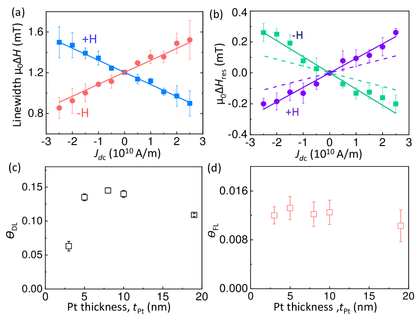
Figure 3(a,b) shows the effect of on and . The linear dependence on current indicates that Joule heating contributions Safranski et al. (2017) are minimal in these measurements. By reversing the magnetization direction (external magnetic field direction), we observe a reversal in the slope for (or ) versus consistent with the symmetry of the SOTs Sinova et al. (2015); Ramaswamy et al. (2018).
From the linear slope of linewidth versus (Fig. 3(a)), the damping-like SOT efficiency is readily quantified with Liu et al. (2011b); Nan et al. (2015)
| (1) |
where , GHz/T is the gyromagnetic ratio of MAFO Emori et al. (2018a), is the microwave frequency (e.g., GHz in Figs. 2 and 3), nm is the MAFO thickness, and or is the in-plane magnetization orientation with respect to the current axis (-axis in Fig. 2(a)). In applying Eq. 1, we account for the sample-to-sample variation in the saturation magnetization kA/m (determined by SQUID magnetometry) and the effective magnetization T (determined by fitting the frequency dependence of resonance field Emori et al. (2018a)). The large effective magnetization of epitaxial MAFO arises due to significant magnetoelastic easy-plane anisotropy Emori et al. (2018a).
The dependence of is summarized in Fig. 3(c). The increase in with up to 5 nm (Fig. 3(c)) suggests that the spin-Hall effect in the Pt bulk is the dominant source of the damping-like SOT Haney et al. (2013); Nguyen et al. (2016). The decrease in at higher might seem surprising, but a similar trend has been observed in prior experiments Nguyen et al. (2016).
We also quantify the field-like SOT efficiency from the linear shift of with (Fig. 3(b)) and subtracting the Oersted field contribution Nan et al. (2015); Pai et al. (2015)
| (2) |
where the term proportional to accounts for the Oersted field. As shown in Fig. 3(d), the constant value of with Pt thickness implies that the field-like SOT arises from the MAFO/Pt interface, e.g., via the Rashba-Edelestein effect Kalitsov et al. (2017); Manchon et al. (2015); Gambardella and Miron (2011). However, this field-like SOT is weak, i.e., similar in magnitude to the Oersted field (Fig. 3(b)). Indeed, we find that is about an order of magnitude smaller than .
Based on the dominance of the strongly -dependent damping-like SOT over the -independent field-like SOT, we conclude that charge-spin interconversion processes in the bulk of Pt dominate over those at the MAFO/Pt interface. It has been proposed that a field-like SOT could arise from the bulk of Pt in the presence of an imaginary part of the spin-mixing conductance, Im Roy (2020). A substantial Im would manifest in a shift in the gyromagnetic ratio (or -factor) in MAFO with the addition of a Pt overlayer Tserkovnyak et al. (2002). Since such a shift is not observed, we rule out this scenario of a field-like SOT of “bulk” origin. In other words, the damping-like torque is the predominant type of SOT that arises from the bulk of Pt. Therefore, in the following sections, we use the damping-like SOT as a measure of charge-to-spin conversion in Pt.
III.2 Modeling the Pt-Thickness Dependence of the Spin-Pumping Damping and Damping-Like Spin-Orbit Torque
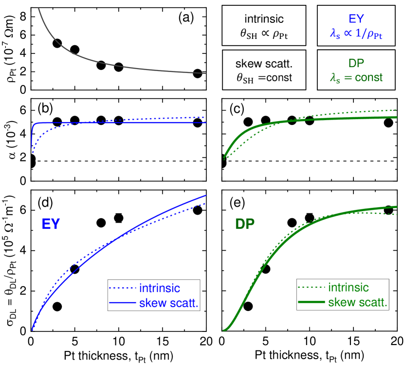
We employ a model similar to the one used by Berger et al. Berger et al. (2018) to assess charge-spin interconversion mechanisms in Pt. This model estimates key parameters that govern charge-spin interconversion by fitting the dependence of two experimentally measured quantities: the Gilbert damping parameter and the damping-like SOT conductivity .
We have measured the damping parameter by coplanar-waveguide-based FMR and ST-FMR, which yield consistent results for unpatterned and patterned MAFO/Pt (see Appendix A). As can be seen in Fig. 4(b,c), MAFO/Pt bilayers exhibit higher than the bare MAFO films with = 0. In Sec. III.3, we attribute this damping enhancement to spin pumping Tserkovnyak et al. (2002), i.e., due to the loss of spin angular momentum pumped from the resonantly excited MAFO layer to the adjacent spin sink layer of Pt. In Sec. III.4, we further consider an additional contribution to the enhancement of due to spin-memory loss or two-magnon scattering.
To parameterize the strength of the damping-like SOT, we employ the “SOT conductivity,” . Normalizing by the Pt resistivity makes explicit the relationship between the SOT and electronic transport. We also remark that is equivalent to the SOT efficiency per unit electric field in Refs. (38; 42). The dependence of (fit curve in Fig. 4(a)) is interpolated by using the empirical model outlined in Appendix D.
In contrast to Ref. (23) that studies FM/Pt bilayers where electronic spin transport in the FM can generally yield additional effects that impact SOTs, our MAFO/Pt system restricts the source of SOTs to Pt. We are therefore able to examine the spin-Hall effect of Pt without any complications from an electrically conductive FM.
To model our experimental results, we consider two types of spin-Hall effect Hoffmann (2013); Sinova et al. (2015):
-
•
the intrinsic mechanism, where the internal spin-Hall ratio – i.e., the charge-to-spin conversion efficiency within the Pt layer itself – is proportional to , with a constant internal spin-Hall conductivity = /;
-
•
the skew scattering mechanism, where is independent of .
We also consider two mechanisms of spin relaxation that govern the spin diffusion length in Pt Boone et al. (2015); Ryu et al. (2016); Freeman et al. (2018):
-
•
Elliott-Yafet (EY) spin relaxation, where spins depolarize during scattering such that scales inversely with , i.e., ;
-
•
Dyakonov-Perel (DP) spin relaxation, where spins depolarize between scattering events such that is independent of (as outlined by Boone et al. Boone et al. (2015)).
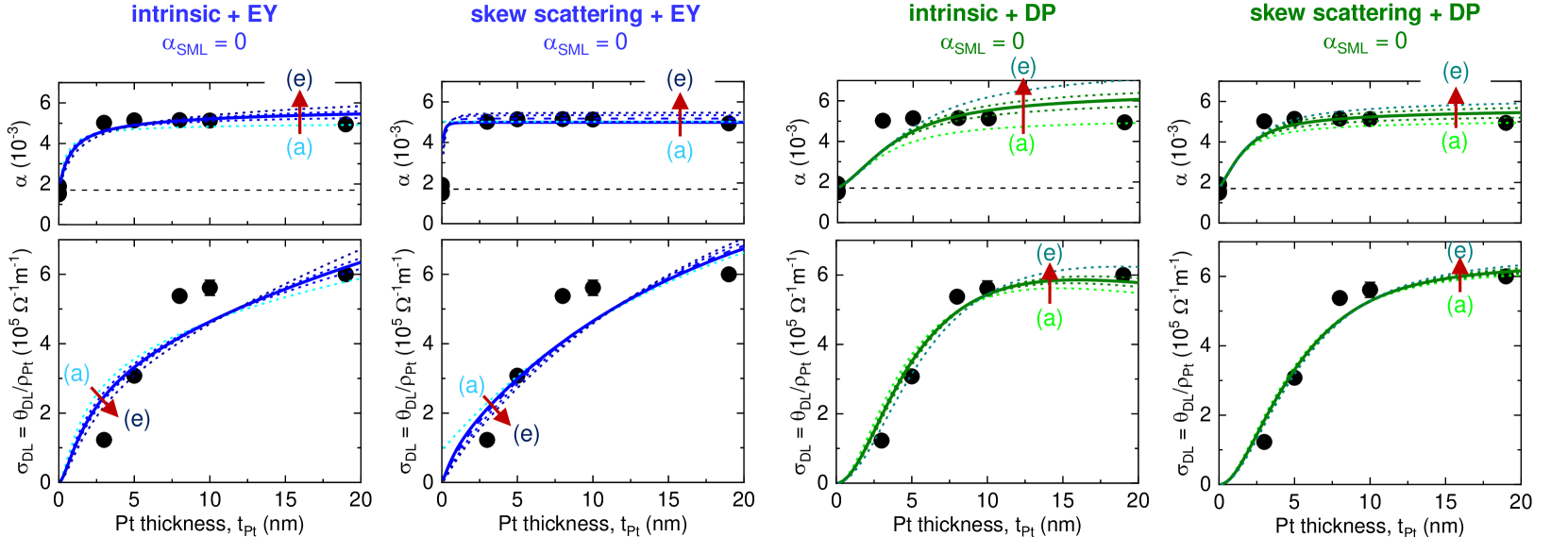
Thus, we model four combinations of the above-listed charge-to-spin conversion and spin relaxation mechanisms, as shown in Fig. 4(b-e).
Similar to Ref. (23), we self-consistently fit vs. (Fig. 4(b,c)) and vs. (Fig. 4(d,e)) by using standard spin diffusion models Tserkovnyak et al. (2002); Boone et al. (2015); Haney et al. (2013), as elaborated in Appendix E, with four free parameters:
-
•
spin diffusion length in the case of DP spin relaxation, or its bulk-limit value in the case of EY spin relaxation;
-
•
internal spin-Hall ratio of Pt in the case of skew scattering, or its bulk-limit value in the case of intrinsic spin-Hall effect;
-
•
real part of the spin-mixing conductance at the MAFO/Pt interface, neglecting the imaginary part as justified in Sec. III.1;
-
•
effective damping enhancement due to interfacial spin-memory loss or two-magnon scattering, as discussed in detail in Sec. III.4.
A key assumption here is that the spin-pumping damping and damping-like SOT share the same values of , , and . This is justified by the enforcement of Onsager reciprocity on the charge-spin interconversion processes of spin pumping and SOT Brataas et al. (2011); Berger et al. (2018). We also assume a negligible interfacial contribution to the spin-Hall effect in Pt Wang et al. (2016), which would yield a finite value of when is extrapolated to zero. Indeed, as shown in Fig. 4, the dependence of is adequately modeled without incorporating the interfacial spin-Hall effect.
For simplicity, we first proceed by setting in Sec. III.3. This is a reasonable assumption considering that interfacial spin-memory loss is likely much weaker in MAFO/Pt than in all-metallic FM/Pt systems Rojas-Sánchez et al. (2014); Chen and Zhang (2015); Dolui and Nikolić (2017); Berger et al. (2018); Zhu et al. (2019a); Caminale et al. (2016); Zhang et al. (2015a). Nevertheless, we also discuss the consequence of in Sec. III.4.
III.3 Mechanisms and Parameters for Charge-Spin Interconversion in Pt: Zero Spin-Memory Loss
Our modeling results under the assumption of zero spin-memory loss are summarized in Fig. 4 and Table 1. We find that the combination of skew scattering and DP spin relaxation (solid green curves in Fig. 4(c,e)) best reproduces the dependence of both and . Although this observation does not necessarily rule out the coexistence of other mechanisms Ryu et al. (2016); Freeman et al. (2018); Dai et al. (2019); Berger et al. (2018), it suggests the dominance of the skew scattering + DP combination in the epitaxial Pt film. Skew scattering in highly crystalline Pt is consistent with what is expected for “superclean” Pt, in contrast to the intrinsic spin-Hall effect that is dominant in “moderately dirty” Pt Sagasta et al. (2016).
The dominance of DP spin relaxation – i.e., spin depolarization (dephasing) from precession about effective spin-orbit fields – is perhaps surprising, since it is usually thought to be inactive in centrosymmetric metals (e.g., Pt). Indeed, in the context of spin transport in Pt, it is typical to assume EY spin relaxation where spins depolarize when their carriers (e.g., electrons) are scattered Nguyen et al. (2016); Stamm et al. (2017); Swindells et al. (2019); Zhu et al. (2019b); Du et al. (2020). However, a recent quantum transport study indicates the dominance of DP spin relaxation in crystalline Pt Ryu et al. (2016), which is in line with our conclusion here. Possible origins of the DP mechanism include symmetry breaking between the substrate and the surface of the crystalline Pt film Long et al. (2016) and strong spin mixing caused by the distinct band structure (large spin Berry curvature) of Pt Freeman et al. (2018). DP spin relaxation may also be more pronounced when proximity-induced magnetism in Pt is negligible Freeman et al. (2018), as is likely the case for Pt interfaced with the insulating MAFO Gray et al. (2018b). We also note that DP spin relaxation has been previously used to model the angular dependence of spin-Hall magnetoresistance Althammer et al. (2013); Chen et al. (2013) in MAFO/Pt Riddiford et al. (2019). The combination of skew scattering and DP spin relaxation, though not reported in prior SOT experiments, is reasonable for MAFO/Pt.
| model | (m-2) | (nm) | ||
|---|---|---|---|---|
| intrinsic + EY | 0 | 21 | 0.21 | |
| skew scatt. + EY | 0 | 4.7 | 1.2 | |
| intrinsic + DP | 0 | 5.7 | 0.25 | |
| skew scatt. + DP | 0 | 3.3 | 0.83 |
We now discuss the parameters quantified with our model, as summarized in the “skew scatt.+DP” row in Table 1. The value of m-2 is comparable to those previously reported for FI/Pt interfaces Sun et al. (2013); Hahn et al. (2013); Wang et al. (2014); Riddiford et al. (2019), and nm is in the intermediate regime of nm in prior reports on Pt Liu et al. (2011a); Morota et al. (2011); Kondou et al. (2012); Zhang et al. (2013); Niimi et al. (2013); Rojas-Sánchez et al. (2014); Wang et al. (2014); Isasa et al. (2015); Boone et al. (2015); Zhang et al. (2015b); Sagasta et al. (2016); Nguyen et al. (2016); Stamm et al. (2017); Berger et al. (2018); Tao et al. (2018); Swindells et al. (2019); Zhu et al. (2019b); Dai et al. (2019).
We find a large internal spin-Hall ratio of . While a few studies have alluded to on the order of unity in transition metals Zhu et al. (2019b); Berger et al. (2018); Wang et al. (2014); Weiler et al. (2014); Keller et al. (2019), our experimental study is the first to derive such a large value in Pt without uncertainties from a conductive FM Weiler et al. (2014); Zhu et al. (2019b); Berger et al. (2018); Keller et al. (2019) or microwave calibration Wang et al. (2014); Weiler et al. (2014); Berger et al. (2018); Keller et al. (2019). Our finding of approaching unity is also distinct from previously reported spin-Hall ratios in all-epitaxial FM/Pt Huo et al. (2017); Keller et al. (2018); Guillemard et al. (2018); Ryu et al. (2019); Du et al. (2020). This discrepancy may be partially explained by the conductive FM reducing the apparent charge-to-spin conversion efficiency, or by the indirect nature of the measurements in these reports. With direct SOT measurements on the model-system MAFO/Pt bilayers, our study points to the possibility of a strong spin-Hall effect in highly crystalline Pt in the skew-scattering regime, where the charge-to-spin conversion efficiency could be greater than the limit set by the intrinsic spin-Hall effect Hoffmann (2013); Sinova et al. (2015); Sagasta et al. (2016); Zhu et al. (2019b).
III.4 Mechanisms and Parameters for Charge-Spin Interconversion in Pt: Finite Spin-Memory Loss
A natural question at this point is how finite spin-memory loss at the MAFO/Pt interface impacts the parameters quantified in our modeling. Moreover, while bare MAFO exhibits negligible two-magnon scattering Emori et al. (2018a), an overlayer (Pt in this case) on top of MAFO may give rise to two-magnon scattering at the interface Wisser et al. (2019b). Both spin-memory loss and two-magnon scattering would have the same consequence in that they enhance the apparent damping parameter, , independent of Berger et al. (2018); Zhu et al. (2019c). We therefore model spin-memory loss and two-magnon scattering with a phenomenological parameter, .

| intrinsic + EY | skew scatt. + EY | intrinsic + DP | skew scatt. + DP | |||||||||
|---|---|---|---|---|---|---|---|---|---|---|---|---|
| (m-2) | (nm) | (m-2) | (nm) | (m-2) | (nm) | (m-2) | (nm) | |||||
| 0 | 21 | 0.21 | 4.7 | 1.2 | 5.7 | 0.25 | 3.3 | 0.83 | ||||
| 0.001 | 23 | 0.40 | 4.7 | 2.7 | 6.2 | 0.53 | 3.6 | 1.5 | ||||
| 0.002 | 26 | 1.3 | 5.0 | 7.5 | 7.1 | 1.2 | 3.8 | 4.1 | ||||
Figure 5 and Table 2 summarize our modeling results incorporating finite spin-memory loss or two-magnon scattering (i.e., ). Finite does not improve the fit quality in vs. of the EY models (Fig. 5(a,b)). By contrast, the fit quality is improved for the DP models with increasing , particularly in vs. (Fig. 5(c,d)). We therefore focus on the results for the DP models.
As shown in Table 2, increasing significantly decreases , consistent with the reduced share of spin pumping in the damping enhancement. To compensate for the smaller , the internal spin-Hall ratio must increase to reproduce the dependence of (Ref. (87)). In the “skew scattering + DP” model, shown to be most plausible in Sec. III.3, increases to values exceeding unity with finite . At a sufficiently large of , the “intrinsic + DP” model appears to becomes plausible (see Fig. 5(c)), but this scenario also yields .
In both of the above DP scenarios, substantial spin-memory loss or two-magnon scattering apparently leads to an unphysically large value of internal spin-Hall ratio in Pt exceeding unity. It is then reasonable to conclude that spin-memory loss and two-magnon scattering is negligibly small in epitaxial MAFO/Pt. This is in stark contrast to the large spin-memory loss deduced for all-metallic FM/Pt bilayers Berger et al. (2018). The small spin-memory loss in MAFO/Pt also suggests fundamentally different spin-transport mechanisms between FM/Pt and FI/Pt systems, which could be exploited for more efficient SOT devices in the future. Our finding motivates further studies to test whether the negligible spin-memory loss is due to the crystalline growth or due to the absence of proximity-induced magnetism.
III.5 Implications of the Large Internal Spin-Hall Ratio in Pt
From our analysis in Sec. III.3, we have arrived at a large internal spin-Hall ratio of in epitaxial Pt. Yet, the observed spin-torque efficiency of implies an interfacial spin transparency ratio of . In other words, at most only 20% of the spin accumulation generated by the spin-Hall effect in Pt is transferred to the magnetic MAFO layer as the damping-like SOT. The origin of this inefficient spin transfer, according to the spin diffusion model employed here, is the small spin-mixing conductance of m-2, which is several times lower than computationally predicted for FM/Pt interfaces Liu et al. (2014); Mahfouzi et al. (2017); Zhao et al. (2018). The small results in a substantial spin backflow Zhu et al. (2019c, 2021) that prevents efficient transmission of spin angular momentum across the MAFO/Pt interface. We emphasize that spin-memory loss is likely negligible at the MAFO/Pt interface (see Sec. III.4) and hence not responsible for the inefficient spin transfer.
There may be an opportunity to enhance the spin transparency – and hence the SOT efficiency – by engineering the interface. One possible approach is to use an ultrathin insertion layer of NiO, which has been reported to increase the spin transparency ratio to essentially unity in FM/Pt systems Zhu et al. (2021). However, it remains to be explored whether the ultrathin NiO insertion layer can increase the spin transparency without causing substantial interfacial spin scattering Wisser et al. (2019b) in FI/Pt bilayers. An increased spin transparency (via enhanced ) also leads to higher spin-pumping damping Tserkovnyak et al. (2002); Brataas et al. (2012), which may not be desirable for applications driven by precessional switching or auto-oscillations.
Another striking implication of the large internal spin-Hall ratio is a large maximum spin-Hall conductivity of m-1, which is at least an order of magnitude greater than m-1 typically predicted from band structure calculations Tanaka et al. (2008); Guo et al. (2008); Obstbaum et al. (2016); Go et al. (2018); Derunova et al. (2019). It should be noted, however, that these calculations are for the intrinsic spin-Hall effect, whereas our experimental data are best captured by the extrinsic spin-Hall effect of skew scattering. We thus speculate that this difference in mechanism could account for the discrepancy in derived from our experimental work and from prior calculations.
Finally, we comment on remaining open fundamental questions. Comparing MAFO/epitaxial-Pt and MAFO/polycrystalline-Pt could reveal the critical role of crystallinity in charge-spin interconversion, spin relaxation, and the internal spin-Hall ratio in Pt. This comparison study is precluded here due to the difficulty in growing polycrystalline Pt on MAFO; Pt has a strong tendency to be epitaxial on MAFO due to the excellent lattice match, even when Pt is sputter-deposited with the substrate at room temperature. Moreover, while the epitaxial Pt film on MAFO is single-crystalline in the sense that its out-of-plane crytallographic orientation is exclusively (111), it is yet unclear how the twin domains (discussed in Sec. II) influence charge-spin interconversion in Pt. Determining the impact of microstructure on spin-Hall and related effects in Pt remains a subject of future work.
Furthermore, we acknowledge the possibility that the model employed in our present study (outlined in Sec. III.2 and Appendix E) is incomplete. For instance, we have assumed that the damping-like SOT and spin-pumping damping are reciprocal phenomena with shared and . This commonly made assumption Berger et al. (2018) – with prior studies suggesting that such reciprocity holds Nan et al. (2015); Emori et al. (2018b) – is necessary for constraining the fitting of the limited number of experimental data points. Further studies are required for confirming whether the damping-like SOT and spin-pumping damping can be captured by the same values of and .
IV Summary
We have measured SOTs in a low-damping, epitaxial insulating spinel ferrite (MgAl0.5Fe1.5O4, MAFO) interfaced with epitaxial Pt. This model-system bilayer enables a unique opportunity to examine charge-spin interconversion mechanisms in highly crystalline Pt, while eliminating complications from electronic transport in (or hybridization with) a magnetic metal. Our key findings are as follow.
-
1.
Charge-to-spin conversion in Pt appears to be primarily a bulk effect, rather than an interfacial effect. A sizable damping-like SOT, which depends strongly on the Pt thickness, arises from the spin-Hall effect within Pt. An order-of-magnitude smaller field-like SOT, independent of the Pt thickness, is attributed to the Rashba-Edelstein effect at the MAFO/Pt interface.
-
2.
In crystalline Pt, the extrinsic spin-Hall effect of skew scattering and the Dyakonov-Perel spin relaxation mechanism likely dominate. This is in contrast to the combination of the intrinsic spin-Hall effect and Elliott-Yafet spin relaxation typically reported for Pt-based systems.
-
3.
The internal spin-Hall ratio deduced for crystalline Pt is large, i.e., . While a similar magnitude has been suggested before from experiments on all-metallic FM/Pt bilayers, greater confidence may be placed in our result owing to the cleanliness of the MAFO/Pt system, the direct nature of the SOT measurement method, and the self-consistent modeling of the SOT and spin-pumping damping.
-
4.
Spin-memory loss appears to be minimal in the epitaxial MAFO/Pt system. Modeled scenarios with substantial spin-memory loss yield unphysically large internal spin-Hall ratios that exceed unity.
-
5.
The factor limiting the damping-like SOT efficiency in the MAFO/Pt bilayer, despite the apparently large , is the small spin-mixing conductance . Enhancing while keeping spin-memory loss minimal could increase the SOT efficiency.
Overall, our work demonstrates the utility of epitaxial insulating-ferrite-based heterostructures for understanding spin-transport phenomena in the widely-used spin-Hall metal of Pt, as well as for engineering materials for efficient spintronic devices.
Acknowledgements.
This work was funded by the Vannevar Bush Faculty Fellowship of the Department of Defense under Contract No. N00014-15-1-0045. L.J.R. acknowledges support from the Air Force Office of Scientific Research under Grant No. FA 9550-20-1-0293. J.J.W. acknowledges support from the U.S. Department of Energy, Director, Office of Science, Office of Basic Energy Sciences, Division of Materials Sciences and Engineering under Contract No. DESC0008505. S.X.W. acknowledges funding from NSF Center for Energy Efficient Electronics Science (E3S) and ASCENT, one of six centers in JUMP, a Semiconductor Research Corporation (SRC) program sponsored by DARPA. L.J.R. and M.J.V. acknowledge the National Science Foundation Graduate Fellowships. X.-Q.S. acknowledges support from DOE Office of Science, Office of High Energy Physics under Grant NO. DE-SC0019380. S.E. acknowledges support from the National Science Foundation, Award No. DMR-2003914. Part of this work was performed at the Stanford Nano Shared Facilities (SNSF)/Stanford Nanofabrication Facility (SNF), supported by the National Science Foundation under award ECCS-1542152. S.E. acknowledges Makoto Kohda, Xin Fan, and Vivek Amin for fruitful discussions. P.L. acknowledges Wei Zhang for valuable suggestions in building the ST-FMR system.Appendix A Effect of Sample Processing on the Magnetic Properties of MAFO
We have used both broadband FMR (i.e., with unpatterned films placed on a coplanar waveguide, see Ref. (44) for details) and ST-FMR (i.e., with microwave current injected through patterned 10-m-wide strips) to measure the frequency dependence of FMR linewidth and resonance field. Thus, it is important to confirm the consistency of measurements between the two techniques.
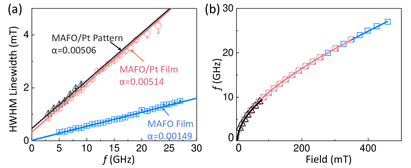
Figure 6(a) plots the linewidth vs. frequency data for a bare MAFO film (13 nm) that we started with, the MAFO (13 nm)/Pt (5 nm) film after Pt deposition, and the ST-FMR pattern with MAFO (13 nm)/Pt (5 nm) after the microfabrication processes. The damping parameters of the MAFO/Pt unpatterned film and patterned strip are essentially identical, confirming the consistency of the broadband FMR and ST-FMR measurements.
We also show in Fig. 6(b) that the frequency dependence of resonance field is unaltered before and after microfabrication. The fit using the Kittel equation Emori et al. (2018a) indicates negligible () difference in the effective magnetization (dominated by mangnetoelastic easy-plane anisotropy) and gyromagnetic ratio for the unpatterned film and patterned strip. The results in Fig. 6 therefore confirm that the microfabrication processes have little to no effect on the essential magnetic properties of MAFO/Pt.
Appendix B Microwave Power Dependence of the Spin-Torque Ferromagnetic Resonance Signal
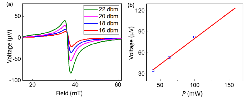
Figure 7 shows the dependence of the ST-FMR signal amplitude on the microwave power. The ST-FMR voltage increases linearly with the microwave power, indicating that all the measurements are done in the linear regime in this present study.
Appendix C Frequency Dependence of the Spin-Orbit Torque Efficiencies
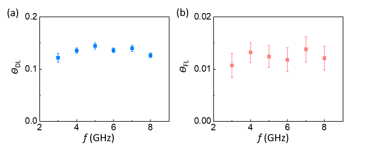
We have carried out a frequency dependence study of damping-like and field-like SOT efficiencies. The dc-biased ST-FMR method is used to extract each data point. Figure 8 shows that both the damping-like and field-like SOT efficiencies are nearly constant across the frequency range of 3-8 GHz. This verifies that the SOT efficiencies are independent of the microwave frequency.
Appendix D Model for the Pt Thickness Dependence of Resistivity
We model the Pt thickness dependence of resistivity by using an approach similar to that reported by Berger et al. Berger et al. (2018). This model takes into account the conductivity as a function of position along the film thickness axis , expressed as the sum of bulk and interfacial contributions,
| (3) |
where m is the bulk resistivity of Pt, is the interfacial resistivity, and is an empirical characteristic length scale capturing the decay of the interfacial contribution to resistivity. The resistivity of the Pt film with thickness is then given by,
| (4) |
The fit curve for the experimentally measured -dependence of (Fig. 4(a)) is obtained with Eq. 4 with m and nm.
| intrinsic + EY | skew scatt. + EY | intrinsic + DP | skew scatt. + DP | |||||||||
|---|---|---|---|---|---|---|---|---|---|---|---|---|
| (m-2) | (nm) | (m-2) | (nm) | (m-2) | (nm) | (m-2) | (nm) | |||||
| (a) | 1.5 | 16 | 0.24 | 1.0 | 0.1 | 48 | 1.2 | 5.7 | 0.32 | 1.1 | 3.2 | 0.96 |
| (b) | 2.0 | 19 | 0.22 | 1.1 | 4.7 | 1.2 | 1.6 | 5.6 | 0.27 | 1.2 | 3.3 | 0.89 |
| (c) | 2.5 | 21 | 0.21 | 1.2 | 5.7 | 0.96 | 1.8 | 5.7 | 0.25 | 1.3 | 3.3 | 0.83 |
| (d) | 3.0 | 22 | 0.20 | 1.3 | 6.7 | 0.80 | 2.0 | 5.8 | 0.23 | 1.4 | 3.4 | 0.77 |
| (e) | 5.0 | 24 | 0.19 | 1.4 | 6.1 | 0.68 | 2.5 | 6.1 | 0.21 | 1.5 | 3.5 | 0.72 |
Appendix E Equations for the Pt Thickness Dependence of and
We fit the dependence of with Boone et al. (2015)
| (5) |
where is the mean value for the five bare MAFO films () prior to Pt deposition for the MAFO/Pt bilayers, is the spin-pumping contribution to Gilbert damping, is the phenomenological parameter capturing the -independent enhancement of damping (from interfacial spin-memory loss or two-magnon scattering), is the spectroscopic -factor Emori et al. (2018a), kA/m is the mean value of the saturation magnetization of MAFO used in this study, and nm is the thickness of MAFO.
The dependence of is fit with Haney et al. (2013)
| (6) |
where . We also remark that is dependent on as given by Eq. 4.
By using Equations 5 and 6, along with the interpolated (Eq. 4), we find the values of , , and that adequately capture the experimentally measured and . In particular, and are fit simultaneously 111We used the MATLAB function of nlinmultifit, which is a wrapper for nlinfit that allows for simultaneous fitting of multiple data sets with shared parameters, available at: https://www.mathworks.com/matlabcentral/fileexchange/40613-multiple-curve-fitting-with-common-parameters-using-nlinfit with a series of fixed values for (e.g., Figs. 9 and Table 3).
References
- Sinova et al. (2015) J. Sinova, S. O. Valenzuela, J. Wunderlich, C. H. Back, and T. Jungwirth, Rev. Mod. Phys. 87, 1213 (2015).
- Ramaswamy et al. (2018) R. Ramaswamy, J. M. Lee, K. Cai, and H. Yang, Appl. Phys. Rev. 5, 031107 (2018).
- Hoffmann (2013) A. Hoffmann, IEEE Trans. Magn. 49, 5172 (2013).
- Manchon et al. (2015) A. Manchon, H. C. Koo, J. Nitta, S. M. Frolov, and R. A. Duine, Nat. Mater. 14, 871 (2015).
- Brataas and Hals (2014) A. Brataas and K. M. D. Hals, Nat. Nanotechnol. 9, 86 (2014).
- Haney et al. (2013) P. M. Haney, H.-W. Lee, K.-J. Lee, A. Manchon, and M. D. Stiles, Phys. Rev. B 87, 174411 (2013).
- Taniguchi et al. (2015) T. Taniguchi, J. Grollier, and M. D. Stiles, Phys. Rev. Appl. 3, 044001 (2015).
- Amin and Stiles (2016) V. P. Amin and M. D. Stiles, Phys. Rev. B 94, 104420 (2016).
- Amin et al. (2018) V. P. Amin, J. Zemen, and M. D. Stiles, Phys. Rev. Lett. 121, 136805 (2018).
- Humphries et al. (2017) A. M. Humphries, T. Wang, E. R. J. Edwards, S. R. Allen, J. M. Shaw, H. T. Nembach, J. Q. Xiao, T. J. Silva, and X. Fan, Nat. Commun. 8, 911 (2017).
- Baek et al. (2018) S.-h. C. Baek, V. P. Amin, Y.-W. Oh, G. Go, S.-J. Lee, G.-H. Lee, K.-J. Kim, M. D. Stiles, B.-G. Park, and K.-J. Lee, Nat. Mater. 2018 , 1 (2018).
- Gibbons et al. (2018) J. D. Gibbons, D. MacNeill, R. A. Buhrman, and D. C. Ralph, Phys. Rev. Appl. 9, 064033 (2018).
- Iihama et al. (2018) S. Iihama, T. Taniguchi, K. Yakushiji, A. Fukushima, Y. Shiota, S. Tsunegi, R. Hiramatsu, S. Yuasa, Y. Suzuki, and H. Kubota, Nat. Electron. 1, 120 (2018).
- Safranski et al. (2019) C. Safranski, E. A. Montoya, and I. N. Krivorotov, Nat. Nanotechnol. 14, 27 (2019).
- Wang et al. (2019) W. Wang, T. Wang, V. P. Amin, Y. Wang, A. Radhakrishnan, A. Davidson, S. R. Allen, T. J. Silva, H. Ohldag, D. Balzar, B. L. Zink, P. M. Haney, J. Q. Xiao, D. G. Cahill, V. O. Lorenz, and X. Fan, Nat. Nanotechnol. 14, 819 (2019).
- Wu et al. (2019) H. Wu, S. A. Razavi, Q. Shao, X. Li, K. L. Wong, Y. Liu, G. Yin, and K. L. Wang, Phys. Rev. B 99, 184403 (2019).
- Zhou et al. (2015) L. Zhou, V. L. Grigoryan, S. Maekawa, X. Wang, and J. Xiao, Phys. Rev. B 91, 045407 (2015).
- Garello et al. (2013) K. Garello, I. M. Miron, C. O. Avci, F. Freimuth, Y. Mokrousov, S. Blügel, S. Auffret, O. Boulle, G. Gaudin, and P. Gambardella, Nat. Nanotechnol. 8, 587 (2013).
- Pai et al. (2015) C.-F. Pai, Y. Ou, L. H. Vilela-Leão, D. C. Ralph, and R. A. Buhrman, Phys. Rev. B 92, 064426 (2015).
- Rojas-Sánchez et al. (2014) J.-C. Rojas-Sánchez, N. Reyren, P. Laczkowski, W. Savero, J.-P. Attané, C. Deranlot, M. Jamet, J.-M. George, L. Vila, and H. Jaffrès, Phys. Rev. Lett. 112, 106602 (2014).
- Chen and Zhang (2015) K. Chen and S. Zhang, Phys. Rev. Lett. 114, 126602 (2015).
- Dolui and Nikolić (2017) K. Dolui and B. K. Nikolić, Phys. Rev. B 96, 220403 (2017).
- Berger et al. (2018) A. J. Berger, E. R. J. Edwards, H. T. Nembach, O. Karis, M. Weiler, and T. J. Silva, Phys. Rev. B 98, 024402 (2018).
- Zhu et al. (2019a) L. Zhu, D. C. Ralph, and R. A. Buhrman, Phys. Rev. Lett. 122, 077201 (2019a).
- Zhang et al. (2015a) W. Zhang, M. B. Jungfleisch, W. Jiang, Y. Liu, J. E. Pearson, S. G. E. te Velthuis, A. Hoffmann, F. Freimuth, and Y. Mokrousov, Phys. Rev. B 91, 115316 (2015a).
- Caminale et al. (2016) M. Caminale, A. Ghosh, S. Auffret, U. Ebels, K. Ollefs, F. Wilhelm, A. Rogalev, and W. E. Bailey, Phys. Rev. B 94, 014414 (2016).
- Amin et al. (2019) V. P. Amin, J. Li, M. D. Stiles, and P. M. Haney, Phys. Rev. B 99, 220405 (2019).
- Liu et al. (2011a) L. Liu, R. A. Buhrman, and D. C. Ralph, , 32 (2011a), arXiv:1111.3702 .
- Morota et al. (2011) M. Morota, Y. Niimi, K. Ohnishi, D. H. Wei, T. Tanaka, H. Kontani, T. Kimura, and Y. Otani, Phys. Rev. B 83, 174405 (2011).
- Kondou et al. (2012) K. Kondou, H. Sukegawa, S. Mitani, K. Tsukagoshi, and S. Kasai, Appl. Phys. Express 5, 073002 (2012).
- Zhang et al. (2013) W. Zhang, V. Vlaminck, J. E. Pearson, R. Divan, S. D. Bader, and A. Hoffmann, Appl. Phys. Lett. 103, 242414 (2013).
- Niimi et al. (2013) Y. Niimi, D. Wei, H. Idzuchi, T. Wakamura, T. Kato, and Y. Otani, Phys. Rev. Lett. 110, 016805 (2013).
- Wang et al. (2014) H. L. Wang, C. H. Du, Y. Pu, R. Adur, P. C. Hammel, and F. Y. Yang, Phys. Rev. Lett. 112, 197201 (2014).
- Isasa et al. (2015) M. Isasa, E. Villamor, L. E. Hueso, M. Gradhand, and F. Casanova, Phys. Rev. B 91, 024402 (2015).
- Boone et al. (2015) C. T. Boone, J. M. Shaw, H. T. Nembach, and T. J. Silva, J. Appl. Phys. 117, 223910 (2015).
- Zhang et al. (2015b) W. Zhang, W. Han, X. Jiang, S.-H. Yang, and S. S. P. Parkin, Nat. Phys. 11, 496 (2015b).
- Sagasta et al. (2016) E. Sagasta, Y. Omori, M. Isasa, M. Gradhand, L. E. Hueso, Y. Niimi, Y. Otani, and F. Casanova, Phys. Rev. B 94, 060412 (2016).
- Nguyen et al. (2016) M.-H. Nguyen, D. C. Ralph, and R. A. Buhrman, Phys. Rev. Lett. 116, 126601 (2016).
- Stamm et al. (2017) C. Stamm, C. Murer, M. Berritta, J. Feng, M. Gabureac, P. M. Oppeneer, and P. Gambardella, Phys. Rev. Lett. 119, 087203 (2017).
- Tao et al. (2018) X. Tao, Q. Liu, B. Miao, R. Yu, Z. Feng, L. Sun, B. You, J. Du, K. Chen, S. Zhang, L. Zhang, Z. Yuan, D. Wu, and H. Ding, Sci. Adv. 4, eaat1670 (2018).
- Swindells et al. (2019) C. Swindells, A. T. Hindmarch, A. J. Gallant, and D. Atkinson, Phys. Rev. B 99, 064406 (2019).
- Zhu et al. (2019b) L. Zhu, L. Zhu, M. Sui, D. C. Ralph, and R. A. Buhrman, Sci. Adv. 5, eaav8025 (2019b).
- Dai et al. (2019) Y. Dai, S. J. Xu, S. W. Chen, X. L. Fan, D. Z. Yang, D. S. Xue, D. S. Song, J. Zhu, S. M. Zhou, and X. Qiu, Phys. Rev. B 100, 064404 (2019).
- Emori et al. (2018a) S. Emori, D. Yi, S. Crossley, J. J. Wisser, P. P. Balakrishnan, P. Shafer, C. Klewe, A. T. N’Diaye, B. T. Urwin, K. Mahalingam, B. M. Howe, H. Y. Hwang, E. Arenholz, and Y. Suzuki, Nano Lett. 18, 4273 (2018a).
- Lee et al. (2019) A. J. Lee, A. S. Ahmed, S. Guo, B. D. Esser, D. W. McComb, and F. Yang, J. Appl. Phys. 125, 183903 (2019).
- Emori et al. (2018b) S. Emori, A. Matyushov, H.-M. Jeon, C. J. Babroski, T. Nan, A. M. Belkessam, J. G. Jones, M. E. McConney, G. J. Brown, B. M. Howe, and N. X. Sun, Appl. Phys. Lett. 112, 182406 (2018b).
- Valvidares et al. (2016) M. Valvidares, N. Dix, M. Isasa, K. Ollefs, F. Wilhelm, A. Rogalev, F. Sánchez, E. Pellegrin, A. Bedoya-Pinto, P. Gargiani, L. E. Hueso, F. Casanova, and J. Fontcuberta, Phys. Rev. B 93, 214415 (2016).
- Gray et al. (2018a) M. T. Gray, S. Emori, B. A. Gray, H. Jeon, O. M. J. van ’t Erve, B. T. Jonker, S. Kim, M. Suzuki, T. Ono, B. M. Howe, and Y. Suzuki, Phys. Rev. Appl. 9, 064039 (2018a).
- Riddiford et al. (2019) L. J. Riddiford, J. J. Wisser, S. Emori, P. Li, D. Roy, E. Cogulu, O. van ’t Erve, Y. Deng, S. X. Wang, B. T. Jonker, A. D. Kent, and Y. Suzuki, Appl. Phys. Lett. 115, 122401 (2019).
- Liu et al. (2011b) L. Liu, T. Moriyama, D. C. Ralph, and R. A. Buhrman, Phys. Rev. Lett. 106, 036601 (2011b).
- Kasai et al. (2014) S. Kasai, K. Kondou, H. Sukegawa, S. Mitani, K. Tsukagoshi, and Y. Otani, Appl. Phys. Lett. 104, 092408 (2014).
- Nan et al. (2015) T. Nan, S. Emori, C. T. Boone, X. Wang, T. M. Oxholm, J. G. Jones, B. M. Howe, G. J. Brown, and N. X. Sun, Phys. Rev. B 91, 214416 (2015).
- Tiwari et al. (2017) D. Tiwari, N. Behera, A. Kumar, P. Dürrenfeld, S. Chaudhary, D. K. Pandya, J. Åkerman, and P. K. Muduli, Appl. Phys. Lett. 111, 232407 (2017).
- Kim et al. (2018) C. Kim, D. Kim, B. S. Chun, K.-W. Moon, and C. Hwang, Phys. Rev. Appl. 9, 054035 (2018).
- Gambardella and Miron (2011) P. Gambardella and I. M. Miron, Philos. Trans. A. Math. Phys. Eng. Sci. 369, 3175 (2011).
- Karnad et al. (2018) G. V. Karnad, C. Gorini, K. Lee, T. Schulz, R. Lo Conte, A. W. J. Wells, D.-S. Han, K. Shahbazi, J.-S. Kim, T. A. Moore, H. J. M. Swagten, U. Eckern, R. Raimondi, and M. Kläui, Phys. Rev. B 97, 100405 (2018).
- Ryu et al. (2016) J. Ryu, M. Kohda, and J. Nitta, Phys. Rev. Lett. 116, 256802 (2016).
- Freeman et al. (2018) R. Freeman, A. Zholud, Z. Dun, H. Zhou, and S. Urazhdin, Phys. Rev. Lett. 120, 067204 (2018).
- Du et al. (2020) Y. Du, H. Gamou, S. Takahashi, S. Karube, M. Kohda, and J. Nitta, Phys. Rev. Appl. 13, 054014 (2020).
- Wisser et al. (2019a) J. J. Wisser, S. Emori, L. Riddiford, A. Altman, P. Li, K. Mahalingam, B. T. Urwin, B. M. Howe, M. R. Page, A. J. Grutter, B. J. Kirby, and Y. Suzuki, Appl. Phys. Lett. 115, 132404 (2019a).
- Lustikova et al. (2014) J. Lustikova, Y. Shiomi, Z. Qiu, T. Kikkawa, R. Iguchi, K. Uchida, and E. Saitoh, J. Appl. Phys. 116, 153902 (2014).
- Chang et al. (2017) H. Chang, T. Liu, D. Reifsnyder Hickey, P. A. P. Janantha, K. A. Mkhoyan, and M. Wu, APL Mater. 5, 126104 (2017).
- Schreier et al. (2015) M. Schreier, T. Chiba, A. Niedermayr, J. Lotze, H. Huebl, S. Geprägs, S. Takahashi, G. E. W. Bauer, R. Gross, and S. T. B. Goennenwein, Phys. Rev. B 92, 144411 (2015).
- Sklenar et al. (2015) J. Sklenar, W. Zhang, M. B. Jungfleisch, W. Jiang, H. Chang, J. E. Pearson, M. Wu, J. B. Ketterson, and A. Hoffmann, Phys. Rev. B 92, 174406 (2015).
- Gonçalves et al. (2013) A. M. Gonçalves, I. Barsukov, Y.-J. Chen, L. Yang, J. A. Katine, and I. N. Krivorotov, Appl. Phys. Lett. 103, 172406 (2013).
- Okada et al. (2019) A. Okada, Y. Takeuchi, K. Furuya, C. Zhang, H. Sato, S. Fukami, and H. Ohno, Phys. Rev. Appl. 12, 014040 (2019).
- Schultheiss et al. (2012) H. Schultheiss, J. E. Pearson, S. D. Bader, and A. Hoffmann, Phys. Rev. Lett. 109, 237204 (2012).
- Safranski et al. (2017) C. Safranski, I. Barsukov, H. K. Lee, T. Schneider, A. A. Jara, A. Smith, H. Chang, K. Lenz, J. Lindner, Y. Tserkovnyak, M. Wu, and I. N. Krivorotov, Nat. Commun. 8, 117 (2017).
- Kalitsov et al. (2017) A. Kalitsov, S. A. Nikolaev, J. Velev, M. Chshiev, and O. Mryasov, Phys. Rev. B 96, 214430 (2017).
- Roy (2020) K. Roy, Appl. Phys. Lett. 117, 022404 (2020), arXiv:2011.11055 .
- Tserkovnyak et al. (2002) Y. Tserkovnyak, A. Brataas, and G. Bauer, Phys. Rev. B 66, 224403 (2002).
- Brataas et al. (2011) A. Brataas, Y. Tserkovnyak, G. E. W. Bauer, and P. J. Kelly, (2011), arXiv:1108.0385 .
- Wang et al. (2016) L. Wang, R. J. H. Wesselink, Y. Liu, Z. Yuan, K. Xia, and P. J. Kelly, Phys. Rev. Lett. 116, 196602 (2016).
- Long et al. (2016) N. H. Long, P. Mavropoulos, D. S. G. Bauer, B. Zimmermann, Y. Mokrousov, and S. Blügel, Phys. Rev. B 94, 180406 (2016).
- Gray et al. (2018b) M. Gray, S. Emori, B. Gray, H. Jeon, O. Van ’T Erve, B. Jonker, S. Kim, M. Suzuki, T. Ono, B. Howe, and Y. Suzuki, Phys. Rev. Appl. 9, 064039 (2018b).
- Althammer et al. (2013) M. Althammer, S. Meyer, H. Nakayama, M. Schreier, S. Altmannshofer, M. Weiler, H. Huebl, S. Geprägs, M. Opel, R. Gross, D. Meier, C. Klewe, T. Kuschel, J.-M. Schmalhorst, G. Reiss, L. Shen, A. Gupta, Y.-T. Chen, G. E. W. Bauer, E. Saitoh, and S. T. B. Goennenwein, Phys. Rev. B 87, 224401 (2013).
- Chen et al. (2013) Y.-T. Chen, S. Takahashi, H. Nakayama, M. Althammer, S. Goennenwein, E. Saitoh, and G. Bauer, Phys. Rev. B 87, 144411 (2013).
- Sun et al. (2013) Y. Sun, H. Chang, M. Kabatek, Y.-Y. Song, Z. Wang, M. Jantz, W. Schneider, M. Wu, E. Montoya, B. Kardasz, B. Heinrich, S. G. E. te Velthuis, H. Schultheiss, and A. Hoffmann, Phys. Rev. Lett. 111, 106601 (2013).
- Hahn et al. (2013) C. Hahn, G. de Loubens, O. Klein, M. Viret, V. V. Naletov, and J. Ben Youssef, Phys. Rev. B 87, 174417 (2013).
- Weiler et al. (2014) M. Weiler, J. M. Shaw, H. T. Nembach, and T. J. Silva, Phys. Rev. Lett. 113, 157204 (2014).
- Keller et al. (2019) M. W. Keller, K. S. Gerace, M. Arora, E. K. Delczeg-Czirjak, J. M. Shaw, and T. J. Silva, Phys. Rev. B 99, 214411 (2019).
- Huo et al. (2017) Y. Huo, F. L. Zeng, C. Zhou, and Y. Z. Wu, AIP Adv. 7, 056024 (2017).
- Keller et al. (2018) S. Keller, L. Mihalceanu, M. R. Schweizer, P. Lang, B. Heinz, M. Geilen, T. Brächer, P. Pirro, T. Meyer, A. Conca, D. Karfaridis, G. Vourlias, T. Kehagias, B. Hillebrands, and E. T. Papaioannou, New J. Phys. 20, 053002 (2018).
- Guillemard et al. (2018) C. Guillemard, S. Petit-Watelot, S. Andrieu, and J.-C. Rojas-Sánchez, Appl. Phys. Lett. 113, 262404 (2018).
- Ryu et al. (2019) J. Ryu, C. O. Avci, S. Karube, M. Kohda, G. S. D. Beach, and J. Nitta, Appl. Phys. Lett. 114, 142402 (2019).
- Wisser et al. (2019b) J. J. Wisser, A. J. Grutter, D. A. Gilbert, A. T. N’Diaye, C. Klewe, P. Shafer, E. Arenholz, Y. Suzuki, and S. Emori, Phys. Rev. Appl. 12, 054044 (2019b).
- Zhu et al. (2019c) L. Zhu, D. C. Ralph, and R. A. Buhrman, Phys. Rev. Lett. 123, 057203 (2019c).
- Liu et al. (2014) Y. Liu, Z. Yuan, R. J. H. Wesselink, A. A. Starikov, and P. J. Kelly, Phys. Rev. Lett. 113, 207202 (2014).
- Mahfouzi et al. (2017) F. Mahfouzi, J. Kim, and N. Kioussis, Phys. Rev. B 96, 214421 (2017).
- Zhao et al. (2018) Y. Zhao, Y. Liu, H. Tang, H. Jiang, Z. Yuan, and K. Xia, Phys. Rev. B 98, 174412 (2018).
- Zhu et al. (2021) L. Zhu, L. Zhu, and R. A. Buhrman, Phys. Rev. Lett. 126, 107204 (2021), arXiv:2102.08487 .
- Brataas et al. (2012) A. Brataas, Y. Tserkovnyak, G. E. W. Bauer, and P. J. Kelly, in Spin Current (2012) Chap. 8, pp. 87–135.
- Tanaka et al. (2008) T. Tanaka, H. Kontani, M. Naito, T. Naito, D. Hirashima, K. Yamada, and J. Inoue, Phys. Rev. B 77, 165117 (2008).
- Guo et al. (2008) G. Y. Guo, S. Murakami, T.-W. Chen, and N. Nagaosa, Phys. Rev. Lett. 100, 096401 (2008).
- Obstbaum et al. (2016) M. Obstbaum, M. Decker, A. K. Greitner, M. Haertinger, T. N. G. Meier, M. Kronseder, K. Chadova, S. Wimmer, D. Ködderitzsch, H. Ebert, and C. H. Back, Phys. Rev. Lett. 117, 167204 (2016).
- Go et al. (2018) D. Go, D. Jo, C. Kim, and H.-W. Lee, Phys. Rev. Lett. 121, 086602 (2018).
- Derunova et al. (2019) E. Derunova, Y. Sun, C. Felser, S. S. P. Parkin, B. Yan, and M. N. Ali, Sci. Adv. 5, eaav8575 (2019).
- Note (1) We used the MATLAB function of nlinmultifit, which is a wrapper for nlinfit that allows for simultaneous fitting of multiple data sets with shared parameters, available at: https://www.mathworks.com/matlabcentral/fileexchange/40613-multiple-curve-fitting-with-common-parameters-using-nlinfit.