CONTRA: Area-Constrained Technology Mapping Framework For Memristive Memory Processing Unit
Abstract.
Data-intensive applications are poised to benefit directly from processing-in-memory platforms, such as memristive Memory Processing Units, which allow leveraging data locality and performing stateful logic operations. Developing design automation flows for such platforms is a challenging and highly relevant research problem. In this work, we investigate the problem of minimizing delay under arbitrary area constraint for MAGIC-based in-memory computing platforms. We propose an end-to-end area constrained technology mapping framework, CONTRA. CONTRA uses Look-Up Table (LUT) based mapping of the input function on the crossbar array to maximize parallel operations and uses a novel search technique to move data optimally inside the array. CONTRA supports benchmarks in a variety of formats, along with crossbar dimensions as input to generate MAGIC instructions. CONTRA scales for large benchmarks, as demonstrated by our experiments. CONTRA allows mapping benchmarks to smaller crossbar dimensions than achieved by any other technique before, while allowing a wide variety of area-delay trade-offs. CONTRA improves the composite metric of area-delay product by to compared to seven existing technology mapping approaches.
1. Introduction
The separation between the processing units and memory unit requires data transfer over energy-hungry buses. This data transfer bottleneck is popularly known as the memory wall. The overhead in terms of energy and delay associated with this transfer of data is considerably higher than the cost of the computation itself (Pedram et al., 2016). Extensive research has been conducted to overcome the memory wall, ranging from the classic memory hierarchy to the close integration of processing units within the memory (Aga et al., 2017; Seshadri et al., 2017). However, these methods still require transfer of data between the processing blocks and the memory, thus falling into the category of von Neumann architectures.
Processing data within the memory has emerged as a promising alternative to the von Neumann architecture. This is generally referred to as Logic-in-Memory (LiM). The primary approach to perform LiM is to store input variables or/and logic output in a memory cell. This is enabled when the physical capabilities of the memory can be used for data storage (as memory) and computation (as logic). Various memory technologies, including Resistive RAM (RRAM), Phase Change Memory (PCM), Spin-transfer torque magnetic random-access memory (STT-MRAM) and others have been used to realize LiM computation (Lehtonen and Laiho, 2009; Agrawal et al., 2018; E. Linn, R. Rosezin, S. Tappertzhofen, U. Böttger and R. Waser, 2012; Gaillardon et al., 2016; Kingra et al., 2020; Kvatinsky et al., 2014; Hamdioui et al., 2015).
RRAM is one of the contending technologies for logic-in-memory computation. RRAMs permit stateful logic, where the logical states are represented as resistive state of the devices and at the same time, are capable of computation. Multiple functionally complete logic families have been successfully demonstrated using RRAM devices (Reuben et al., 2017). In the following, three prominent logic families are presented.
Material Implication Logic (Lehtonen and Laiho, 2009): Consider two RRAM devices and with internal states and respectively, as shown in Fig. 1a. By applying voltages to the terminal, material implication can be computed, with the next state (NS) of device set to the result of computation.
| (1) |
Majority Logic (Gaillardon et al., 2016): In this approach as shown in Fig. 1b, the wordline voltage () and bitline voltages () act as logic inputs, while the internal resistive state of the device acts a third input. The next state of device in this case is a function of three inputs as shown below in the following equation.
| (2) |
Memristor-Aided loGIC (MAGIC) (Kvatinsky et al., 2014). MAGIC allows in-memory compute operation by using the internal resistive state of single or multiple RRAM devices as input. The exact number of inputs () depends on the specific device used for computation. The result of computation is written to a new device (), as shown in Fig. 1c. The internal resistive state of the input devices remain unchanged. Using MAGIC operations, multi-input NOR and NOT can be realized.
| (3) | ||||
| (4) |

General purpose architectures have been proposed based on these primitives. A bit-serial Programmable Logic in Memory (PLiM) architecture was proposed by Gaillardon et al. (Gaillardon et al., 2016) that uses majority as the logic primitive. PLiM relied on using the same crossbar for storage of instructions as well for computation. RRAM-based Very long instruction word (VLIW) Architecture for in-Memory comPuting (ReVAMP) was proposed by Bhattacharjee et al. (Bhattacharjee et al., 2017a), that used Instruction Memory for the instruction storage and a separate RRAM crossbar as data storage and computation memory. Haj Ali et al. proposed memristive Memory Processing Unit (mMPU) (Haj-Ali et al., 2018). The mMPU consists of memristive memory arrays, along with Complementary Metal Oxide Semiconductor (CMOS) periphery and control circuits to allow support for computations as well as conventional data read and write operations. To perform a computation within the mMPU, a compute command is sent to the mMPU controller. The controller generates the corresponding control signals and applies the signals to the crossbar array to perform the actual MAGIC operations. The mMPU allows MAGIC NOR and NOT gates to be executed within any part of the crossbar array, which allows storage of data as well as computation to happen in the same array. Compared to the architectures based on Material Implication, and Majority logic, MAGIC provides an inherent advantage. For MAGIC, control signals are not dependent on the output of a compute operation, .
Wider acceptance of these architectures and technologies critically rely on efficient design automation flows, including logic synthesis and technology mapping. In this paper, we focus on the technology mapping challenge for architectures supporting MAGIC operations. Intuitively, a Boolean function (represented using logic level intermediate form) is processed by the technology mapping flow to generate a sequence of MAGIC operations which are executed on the limited area available on a crossbar. The number of devices available for computation using MAGIC operations on the mMPU is limited (Lee et al., 2017; Xue et al., 2013), which makes the problem of technology mapping even more challenging. This particular variant is known as area-constrained technology mapping problem (ACTMaP) for mMPU. Multiple technology mapping solutions for mMPU have been proposed in the literature (Talati et al., 2016; Thangkhiew and Datta, 2018; Hur et al., 2017; Tenace et al., 2019; Yadav et al., 2019; Ben-Hur et al., 2019). Almost all of these works focus delay reduction, only one (Ben-Hur et al., 2019) accepts a limited form of area constraints (limited row-size only) and considers device reuse to improve area efficiency.
In this paper, we propose CONTRA111Source code available: https://github.com/debjyoti0891/arche – the first scalable area-constrained technology mapping flow for the LiM computing using MAGIC operations. CONTRA not only allows specifying overall area constraint (in terms of number of devices) but also the exact crossbar dimensions. This enables CONTRA to map the same function into say a or crossbar with different delays, whereas the existing methods cannot offer this flexibility. Specifically, our paper makes the following contributions:
-
•
We propose a scalable 2-dimensional area-constrained technology mapping flow for the LiM computing using MAGIC operations.
-
•
We present novel algorithms, using NOR-of-NORs representations (NoN) to place the LUTs on the crossbar to maximize parallelism, while maintaining the area constraints. We use an optimal A* search technique for moving inputs to the required position in the crossbar and propose an input alignment optimization to reduce the number of copy operations.
-
•
We extensively evaluate our technique using various benchmarks. The overall flow achieves improvement in area-delay product from to in terms of geometric mean compared to seven existing technology mapping approaches for MAGIC. Our method can map arbitrary Boolean function using MAGIC operations to a smaller crossbar dimensions than achieved by any other technique before.
CONTRA takes an input benchmark, processes it using the novel technology mapping flow to generates MAGIC instructions. We developed an in-house simulator for MAGIC to execute the instructions and formally verify the functional equivalence of the generated instructions and the input benchmark.
2. Background and Related Works
2.1. MAGIC operations
We present the basics of computing using MAGIC operations to begin with. As shown in Fig. 2(a), a 2-input MAGIC NOR gate consists of 2-input memristors ( and ) and one output memristor (). The memristive state of the output memristor changes in accordance with the resistive states of the input memristors. Low resistive state is interpreted as logical ‘1’ while high resistive state is interpreted as logical ‘0’. The NOR gate operation is realized by applying to the input memristors while the output memristor is grounded. Note that the output memristor has to be initialized to low resistive state before the NOR operation is carried out. After applying the voltage, the resistance of the output memristor is set based on the ratio between the resistances of the input and the output memristors and results in a NOR operation. The MAGIC NOR operation can be performed with the devices arranged in a crossbar configuration, as shown in the right hand side of Fig. 2(a). By extending this approach, it is feasible to perform logical -input NOR and NOT operations.
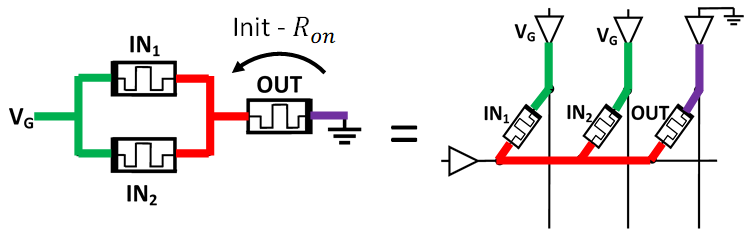
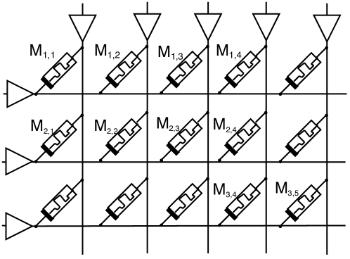

Multiple MAGIC operations can be performed in parallel. The parallel execution of multiple NOR gates is achieved whenever inputs and outputs of the -input NOR gates are aligned in the same rows or columns in a crossbar, as shown in Fig. 2(b). For example, Fig. 2(c), two 3-input NOR operations are performed in parallel.
Also, vertical operations are allowed as shown in Fig. 2(d).
A single-input NOR operation is a NOT gate, as shown in Fig. 2(e).
Thus, both -input NOR and NOT gates can be executed by MAGIC operations. It is also possible to reset the devices in parallel in the crossbar to ‘1’, either row-wise or column-wise.
2.2. Logic Synthesis and Technology Mapping
For logic synthesis and technology mapping approaches, a classification of different Intermediate Representations (IRs) has been proposed in (Soeken and
Chattopadhyay, 2016). First, there are Functional approaches, where the IR is used to explicitly express the logic function. Examples for IRs are Boolean truth tables, Look-Up Tables (LUTs) or Binary Decision Diagrams (BDDs). Second, there are Structural approaches, where the IR is used to represent the structure of the circuit, e.g., using And-Inverter Graphs (AIGs). For technology mapping on memristive crossbar, both types of approaches have been adopted, as it fits more closely the device-level operations. Among the design automation flows developed for memristive technologies, Majority-Inverter Graphs (MIGs) are predominantly used due to their native mapping on to devices supporting Majority Boolean functions (Bhattacharjee et al., 2018; Shirinzadeh et al., 2018). MAGIC devices realize multi-input NOR operations, which do not allow a direct mapping from MIGs. Hence, in this work, we use LUT graph and NOR-of-NOR representations for solving ACTMaP for mMPU. The rationale for using LUT graph is that it allows mapping to all forms of Boolean functions (Tenace et al., 2019).
LUT graph: Any arbitrary Boolean function can be represented as a directed acyclic graph (DAG) , with each vertex having at most -predecessors (Synthesis and
Group, 2016). Each vertex , , with -predecessors represents a -input Boolean function or simply a -input LUT. Each edge, represents a data dependency from the output of node to an input of node .
Example 2.0.
Fig. 3 shows the cm151a benchmark from LGSynth91 as a DAG with . The benchmark has 12 primary inputs and two primary outputs and . LUT has a dependency on LUTs and and on primary input . We use this benchmark as a running example to explain the proposed method.

NOR-of-NOR representation: A Boolean function , expressed in sum-of-products (SoP) form can be converted to the NOR-of-NORs (NoN) representation by the following simple transformations.
-
(1)
Replace and operations with
-
(2)
Flip the polarity of each primary input
-
(3)
Negate the result
For example, we can express in NoN representation as follows.
| (5) |
Alternatively, we can express this NoN as:-
| Variables | |||
|---|---|---|---|
| 1st product term: | 0 | 1 | - |
| 2nd product term: | 1 | 0 | 0 |
2.3. Related Works
Multiple works address the issue of design automation for computation with bound on the number of memristive devices. Lehtonen et al. presented a methodology for computing arbitrary Boolean functions using devices that realize material implication (Lehtonen and Laiho, 2009). For any Boolean function with inputs and outputs, working memristors are required for computing the function. For -input Boolean function with a single output, three working memristors are sufficient for computation. This bound was further reduced to two working memristors by Poikonen et al. (Lehtonen et al., 2010). Optimal and heuristic solutions for ACTMaP for devices realizing majority with single input inverted have been proposed in (Bhattacharjee et al., 2017b). Crossbar-constrained ACTMaP solution has been proposed for devices realizing majority with single input inverted in (Bhattacharjee et al., 2020).
As mentioned before, several technology mapping methods for mMPU have been proposed in literature (Talati et al., 2016; Thangkhiew and Datta, 2018; Hur et al., 2017; Tenace et al., 2019; Yadav et al., 2019; Ben-Hur et al., 2019). These methods primarily work towards reducing latency for mapping an arbitrary function and output the dimensions of the crossbar required to map the function. While trying to maximize parallelism, these methods often map to highly skewed crossbar dimensions (where number of rows is much higher than number of columns or vice versa). Furthermore, this methods are highly area inefficient since they do not reuse devices, leading to very low device utilization. To our knowledge, SIMPLER (Ben-Hur et al., 2019) is currently the only method for mMPU that is optimized for area. SIMPLER relies on mapping functions to a single row, with the objective of achieving high throughput by simultaneously executing multiple data streams in different rows. As SIMPLER allows device reuse, it has high area utilization. However, the utility of this method is limited as all the used devices must still be allocated in a single memory row and it cannot use 2-dimensional crossbar for mapping in order to fit a function into a small crossbar. We address the challenge of 2-dimensional constrained mapping.
3. Area-constrained Technology Mapping Flow
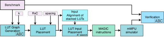
In this section, we describe CONTRA, a 2-dimensional area-Constrained Technology mapping fRAmework for memristive memory processing unit, which is shown in Fig. 4.
3.1. LUT Placement on Crossbar
The goal of this phase is to map the individual nodes (LUTs) of the input DAG on the crossbar, so as to minimize the delay of computing. LUTs in the same topological level of the DAG do not have any dependencies between themselves and therefore, could be scheduled in parallel. In order to permit computation of multiple LUTs in parallel, we utilize the NOR-of-NOR representation of the LUT function.
Since the NoN representation consists of only NOR and NOT operations, it can be computed by MAGIC operations directly in cycles, ignoring the initialization cycle(s). All the variables in appropriate polarity (inverted or regular) in a product term are aligned in rows. For the variables which are not present in a product term, the corresponding memristor is set to ‘1’, which is the state of the memristor after reset. This is followed by computing NOR of all the product terms horizontally in a single cycle. In the next cycle, a vertical NOR of the above results produces the negated output. In the last cycle, we negate this result to get output of the computed function.

Example 3.0.
The computation of in equation (5) using MAGIC operations is shown Fig. 5. Row 1 and row 2 have the inputs for the 1st and 2nd product terms respectively. These inputs are NORed in parallel to compute the product terms with the outputs written to (H1) and (H2). The product terms are vertically NORed to compute in . In the final step, is inverted using a NOT operation to compute (in ).
The LUTs are topologically ordered and grouped by the number of inputs. The LUTs are placed one below another with inputs aligned till we are limited by the height of the crossbar. Consider -LUTs each with -inputs. Once the LUTs are aligned one below another, we can compute the horizontal NOR of all LUTs in one cycle. This is because the inputs and outputs of all the LUTs are aligned and the voltage of the columns applies to all LUTs. In the next -cycles, we can perform the vertical NOR operations to compute the inverted output of the stacked LUTs. Thus, cycles are required to compute the stacked LUTs. Let us consider that each -input LUT has product terms, . Then, the area required to compute the LUTs in parallel is :-
| (6) |
The LUT placement strategy is from top to bottom and from left to right. The parameter is used to specify the number of rows that are left empty between two LUTs stacked vertically. If we do not have enough free devices to place a new LUT, the crossbar is scanned row-wise and column-wise to check in which rows or columns, the intermediate results are present. These are considered blocked and the rest of the crossbar is reset either row-wise or column-wise, which results in lesser number of devices being blocked. . The process is repeated till all the LUTs are placed. The overall flow is presented in Algorithm 1.
Example 3.0.
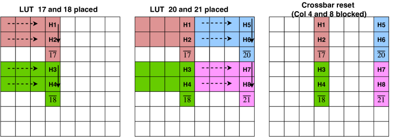
For cm151a, we stack the LUTs and in the crossbar, as shown in Fig. 6. Since enough space in not available vertically, we stack LUTs and on the right. We reset the crossbar, without resetting column and , as these columns contain the intermediate results. We continue placing the other LUTs in similar manner.
1 [LUT 17 (1,1)(3,4) ][ LUT 18 (4,1)(6,4) ] 2 [LUT 20 (1,5)(3,8) ][ LUT 21 (4,5)(6,8) ] 3 [Reset columns except {4,8}] 4
Note that we are effectively computing the inverted output of each LUT. Therefore, for the output LUTs, an additional NOT operation is required, as specified in lines 17-19 of Algorithm 1.
3.2. LUT Input Placement Technique
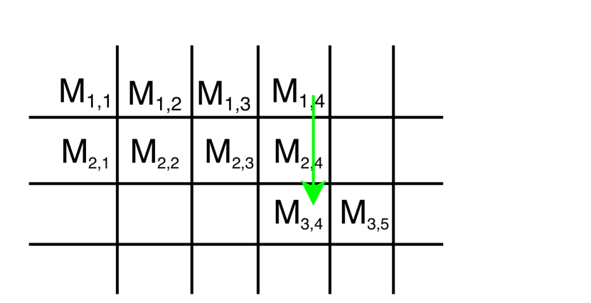
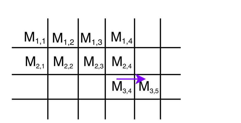
For some of the LUTs,, we require the intermediate outputs from previous computations as inputs. We use search to get the shortest path to copy an intermediate value from source () to destination () with a minimum number of NOT operations. The cost of a location is . is equal to the number of copy operations used to reach from () till .
| (7) |
All empty cells in the row and column of the current location are considered its neighbours. The search starts at the source, updates the cost of the neighbouring location and picks the location with the least . The process is repeated till the goal state is reached. If the path length is odd, the polarity of the input is reversed while for an even length path, the polarity is preserved. This is due to an odd or even number of NOT operations respectively. If the inputs of a NoN has only positive or negative terms, but not both, we need to choose the copy path to be even or odd accordingly. If the inputs are of mixed polarity, we can choose the path with shorter length, the polarity does not matter. Thereafter, the input variable is vertically copied to different rows as required for the other product terms in the LUT, according to the NoN representation.
Example 3.0.
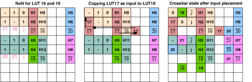
LUT 16 uses the output of LUT 17 as input, with the NoN representation shown in Fig. 7. We copy the value from to using a sequence of NOT operations, obtained using search.
NOT(), NOT(), NOT()
The state of the crossbar after placing all the inputs (LUTs 17, 18, 20 and 21, primary inputs i and j) for LUT and is shown in the last sub-figure of Fig. 7.
3.3. Input Alignment for multiple LUTs
Multiple LUTs scheduled together for execution, often share common inputs. If the common inputs are assigned to the same column, then only a single search would be required to bring the input to the column, and followed by vertically copying to the appropriate rows. This would lead to reduction in delay as well as reduction in the number of devices involved in copying. The goal is to have an assignment of the inputs of the individual LUTs to columns such that it maximizes the number of aligned inputs in a set of stacked LUTs.
We encode the constraints of this problem to optimally solve the problem using an Satisfiability Modulo Theories (SMT) solver.
Maximize
input of LUT . and .
if . , and .
The assignment to variable indicates a variable is assigned to column of LUT . For LUTs each with inputs, a brute force approach would have time complexity of . As the SMT solver takes a long time to solve and have to be executed multiple times in mapping a benchmark, we propose a greedy algorithm for faster mapping.
Consider -input LUTs and of these LUTs stacked together. This can be represented as a matrix with dimensions , where each row represents the inputs variables of the LUT. As the inputs of an LUT are unique, each variable occurs at most once in each row of the matrix. The detailed alignment approach is shown in Algorithm 2. We explain the algorithm with a representative example.
Example 3.0.
Consider the three 4-input LUTs with their input variables arranged as an unaligned matrix, as shown below. The variables are ordered in descending order by frequency. L = {a:3, b:2, c:2, d:1, e:1, h:1, g:1, x:1}. We start the alignment by placing ‘a’ in the first column. In the next step, we place ‘b’. As row 1 and 2 of column 1 are already occupied by ‘a’, we place ‘b’ in column 2. Similarly, we continue the process until all the variables are placed.
| Unaligned | Step 1 | Step 2 | … | Aligned | ||||||||||||||
| a | b | c | d | a | a | b | a | b | c | d | ||||||||
| b | c | e | a | a | a | b | a | b | c | e | ||||||||
| h | a | g | x | a | a | a | h | g | x | |||||||||
Example 3.0.
For the LUTs 16 and 19, the result of alignment is shown in first sub-figure of Fig. 7, specified by variables in pink. The variables 17, 18 and j are assigned columns , and for LUT 17 while the variables 20, 21 and j are assigned columns , and for LUT 18, thereby aligning input variable .
This completes the description of the technique for area-constrained mapping. The output of mapping cm151a benchmark to crossbar with and and is shown in Fig. 8. The benchmark was mapped in 71 cycles. Each line signifies one or more operations with the corresponding input and gate names (pi, old_n_18, etc.) that are executed in the same cycle. In the next section, we present the results of benchmarking the proposed method.

4. Experimental Results
This section presents the experimental results of the CONTRA, the proposed area-Constrained Technology mapping fRAmework for for computing arbitrary functions using MAGIC operations. We have implemented the proposed CONTRA framwork using Python. CONTRA supports a variety of input formats for the benchmarks, including blif, structural verilog, aig. We have used ABC (Synthesis and Group, 2016) for all generating the LUT graph and the SOP representation of LUT functions, which we converted to NoN representation for mapping. For each benchmark, CONTRA generates cycle accurate MAGIC instructions. A representative output of mapping is shown in Fig. 8. We developed an in-house mMPU simulator for executing MAGIC instructions. We used the simulator to generate execution traces which were converted into Verilog. The generated Verilog and the input benchmarks were formally checked for functional equivalence using the cec command of ABC.
| (R,C) | (64,64) | (128,64) | (128,128) | |||
|---|---|---|---|---|---|---|
| Bench | PI | PO | Cycles | Cycles | Cycles | |
| c432 | 36 | 7 | 797 | 774 | 770 | |
| c499 | 41 | 32 | 1391 | 1341 | 1343 | |
| c880 | 60 | 26 | 1314 | 1268 | 1263 | |
| c1355 | 41 | 32 | 1390 | 1341 | 1344 | |
| c1908 | 33 | 25 | 1511 | 1470 | 1469 | |
| c2670 | 233 | 140 | 2132 | 2066 | 2060 | |
| c3540 | 50 | 22 | 3751 | 3575 | 3575 | |
| c5315 | 178 | 123 | 5022 | 4827 | 4831 | |
| c6288 | 32 | 32 | 8176 | 7890 | 7881 | |
| c7552 | 207 | 108 | 7308 | 7039 | 7036 |
| (R,C) | (64,64) | (128,64) | (128,128) | ||
|---|---|---|---|---|---|
| Bench | PI | PO | Cycles | Cycles | Cycles |
| arbiter | 256 | 129 | 81941 | 81582 | 81434 |
| cavlc | 10 | 11 | 3808 | 3672 | 3686 |
| ctrl | 7 | 26 | 786 | 759 | 757 |
| dec | 8 | 256 | 1399 | 1253 | 1284 |
| i2c | 147 | 142 | 6698 | 6656 | 6692 |
| int2float | 11 | 7 | 1369 | 1340 | 1323 |
| priority | 128 | 8 | 5479 | 5398 | 5389 |
| router | 60 | 30 | 1150 | 1121 | 1153 |
| voter | 1001 | 1 | - | 68777 | 68758 |
| Bench | PI | PO | LUTs | k | Spacing | Cycles | |
|---|---|---|---|---|---|---|---|
| adder | 256 | 129 | 339 | 4 | 6 | 4398 | |
| bar | 135 | 128 | 1408 | 4 | 6 | 12216 | |
| div | 128 | 128 | 57239 | 2 | 6 | 342330 | |
| hyp | 256 | 128 | 64228 | 4 | - | - | |
| log2 | 32 | 32 | 10127 | 4 | 1 | 128647 | |
| max | 512 | 130 | 1057 | 4 | 6 | 9468 | |
| multiplier | 128 | 128 | 10183 | 3 | 0 | 90925 | |
| sin | 24 | 25 | 1915 | 4 | 6 | 21761 | |
| sqrt | 128 | 64 | 8399 | 4 | 6 | 101694 | |
| square | 64 | 128 | 6292 | 4 | 0 | 74614 |
We benchmark our tool using the ISCAS85 benchmarks (Hansen et al., 1999), which have been used extensively for evaluation of automation flows for MAGIC. The experiments were run on a shared cluster with 16 Intel(R) Xeon(R) CPU E5-2667 v4 @ 3.20GHz, with Red Hat Enterprise Linux 7. Table 1 shows the results of mapping the benchmarks for three crossbar dimensions. We report the execution time in seconds for for the ISCAS85 benchmarks. We report the results for the best delay (in cycles) by varying from to . As expected, the increase in crossbar dimensions results in lower delay of execution. We also report the results of mapping for the EPFL benchmarks222https://github.com/lsils/benchmarks. We report the results for EPFL MIG benchmarks in Table 2 for three crossbar dimensions. For the larger EPFL arithmetic and random control benchmarks, we report the results for crossbar with dimensions in Table 3 and Table 4 respectively.
We observe that for most of the results, the best delay was obtained for . This is because setting a higher value of k, leads to fewer LUTs in the LUT graph. Since multiple LUTs can be scheduled in parallel (based on constraints mentioned in Algorithm 1), this leads to reduction in the number of cycles to compute the benchmark by exploiting higher degree of parallelism. For large benchmark such as voter in Table 2 and very small crossbar dimension (), the mapping flow fails. This happens because during the placement phase of the flow, multiple columns are blocked with intermediate results which does not leave enough number of free devices to map the rest of the LUTs.
| Benchmark | PI | PO | LUTs | Cycles |
|---|---|---|---|---|
| ac97_ctrl | 2255 | 2250 | 3926 | 27742 |
| comp | 279 | 193 | 8090 | 74379 |
| des_area | 368 | 72 | 1797 | 17273 |
| div16 | 32 | 32 | 2293 | 22047 |
| hamming | 200 | 7 | 725 | 9414 |
| i2c | 147 | 142 | 423 | 3133 |
| MAC32 | 96 | 65 | 3310 | 40007 |
| max | 512 | 130 | 1866 | 16072 |
| mem_ctrl | 1198 | 1225 | 3031 | 22021 |
| MUL32 | 64 | 64 | 2758 | 31344 |
| pci_bridge32 | 3519 | 3528 | 23257 | 110318 |
| pci_spoci_ctrl | 85 | 76 | 446 | 3621 |
| revx | 20 | 25 | 3056 | 31603 |
| sasc | 133 | 132 | 204 | 1476 |
| simple_spi | 148 | 147 | 305 | 2307 |
| spi | 274 | 276 | 1581 | 13115 |
| sqrt32 | 32 | 16 | 989 | 11326 |
| square | 64 | 127 | 6083 | 67602 |
| ss_pcm | 106 | 98 | 159 | 968 |
| systemcaes | 930 | 819 | 3207 | 26981 |
| systemcdes | 314 | 258 | 1128 | 9468 |
| tv80 | 373 | 404 | 3044 | 25986 |
| usb_funct | 1860 | 1846 | 5265 | 41029 |
| usb_phy | 113 | 111 | 187 | 1156 |
| Spacing | 0 | 2 | 4 | 6 | 8 | |
|---|---|---|---|---|---|---|
| c3540 | 4006 | 3760 | 3702 | 3761 | 3813 | |
| c5315 | 5354 | 4952 | 4963 | 5032 | 5108 | |
| c7552 | 8009 | 7348 | 7187 | 7327 | ||
| c3540 | 3814 | 3664 | 3639 | 3585 | 3614 | |
| c5315 | 5071 | 4836 | 4795 | 4828 | 4804 | |
| c7552 | 7807 | 7141 | 7052 | 7038 | 7035 |
4.1. Impact of spacing parameter
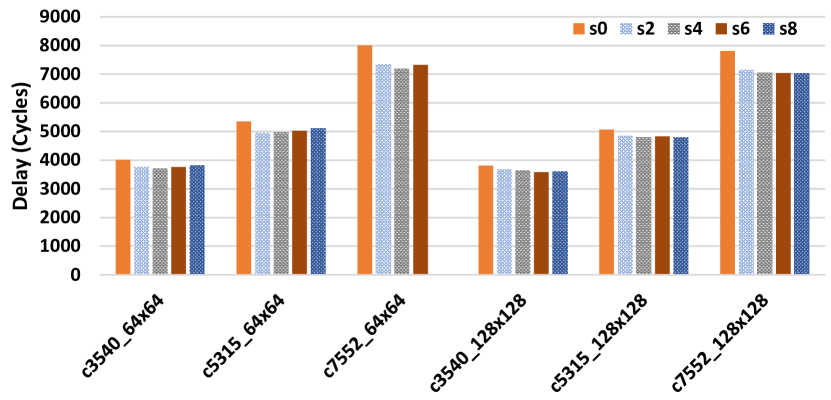
Spacing is the number of rows that is left free between two LUTs stacked vertically, as described in Algorithm 1. We analyze the impact of spacing on three large benchmarks for ISCAS85, and two crossbar dimensions and . The results of analysis are summarily shown in Fig. 9. For most of the benchmarks, the delay decreases considerably by increasing spacing from 0 to 4 or 6 (depending on the benchmark). However, increasing spacing further leads to increase in delay. This is due to the fact that leaving empty row helps in finding shorter paths between source and destination locations on the crossbar while using A* search, that leads to reduction in delay. However, setting a large value (such as 8 or higher) for the spacing parameter leads to lesser space available in the crossbar for actual placement of the LUTs, which leads to reduction in number of parallel operations and higher delay.
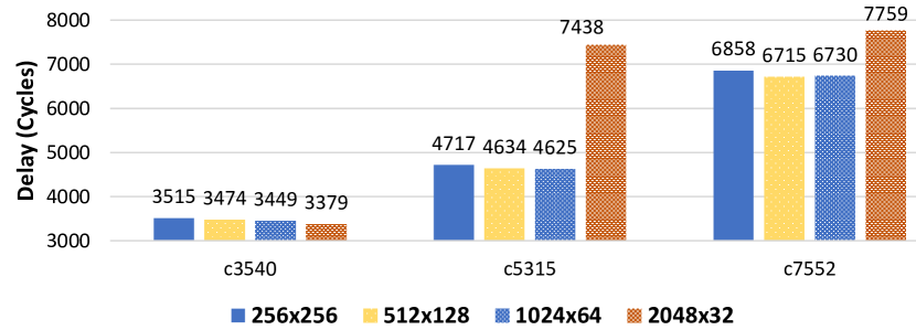
4.2. Impact of crossbar dimensions
Fig. 10 shows the impact of crossbar dimensions on delay of mapping, while keeping the number of devices () constant. We considered , and three large benchmarks for ISCAS85 benchmarks. The best delay for all the benchmarks were obtained for and spacing=. We can observe that increasing the number of rows and decreasing the number of columns, the delay of mapping decreases. As discussed in Section 3, LUTs are stacked in vertical orientation and can be executed in parallel as long as there are no data dependencies and the number of inputs are same. Increasing the number of rows allows greater number of parallel operations to be executed. When a small number of columns are available, the mapping delay increases (as observed by changing crossbar dimensions from to ). This is because lower number of devices are available when columns are blocked during for preserving intermediate results and the alignment overhead increases as well.
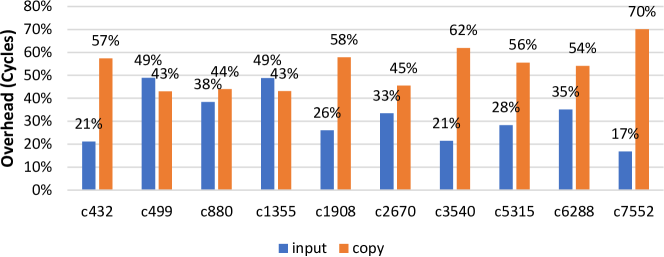
4.3. Copy overhead
Fig. 11 shows the overhead of copy operations as a percentage. As evident from the Fig. 11, copy operations constitute a large overhead in the computation of a benchmark. As we use A* search algorithm to align the inputs, the exact number of copy operations used in alignment is optimal. However in order to limit run time, we do not try and scheduling multiple copy operations in parallel, considering multiple source and destination locations simultaneously. This could be investigated in future, at the cost of higher execution time of the search algorithm.
| Proposed | E1 (Gharpinde et al., 2017) | E2 (Zulehner et al., 2019) | E3 (Thangkhiew and Datta, 2018) | E4 (Thangkhiew and Datta, 2018) | E5 (Yadav et al., 2019) | E6 (Yadav et al., 2019) | E7 (Tenace et al., 2019) | |||||||||||
| Bench | k | RxC | Cycles | RxC | Cycles | RxC | Cycles | RxC | Cycles | RxC | Cycles | RxC | Cycles | RxC | Cycles | RxC | Cycles | |
| c432 | 3 | 20x12 | 824 | 146x9 | 349 | 22x42 | 225 | 62x11 | 265 | 51x47 | 342 | 36x150 | 338 | 69x13 | 290 | 36x84 | 156 | |
| c499 | 3 | 20x16 | 1140 | 323x13 | 1155 | 96x44 | 242 | 73x37 | 935 | 83x55 | 1059 | 45x182 | 903 | 116x31 | 707 | 144x28 | 420 | |
| c880 | 3 | 32x22 | 1389 | 383x5 | 761 | 67x39 | 427 | 124x30 | 750 | 103x73 | 913 | 69x73 | 726 | 107x14 | 613 | 100x53 | 482 | |
| c1355 | 3 | 36x16 | 1092 | 359x10 | 1072 | 96x63 | 236 | 72x43 | 938 | 91x55 | 1060 | 49x163 | 825 | 103x28 | 757 | 128x37 | 554 | |
| c1908 | 3 | 32x22 | 1489 | 312x13 | 1056 | 83x85 | 517 | 60x60 | 970 | 70x66 | 1075 | 42x88 | 928 | 93x33 | 648 | 69x54 | 627 | |
| c2670 | 4 | 38x34 | 2267 | 664x9 | 1490 | 66x92 | 551 | 301x45 | 1401 | 385x245 | 1495 | 202x137 | 1278 | 340x29 | 1183 | 355x33 | 643 | |
| c3540 | 4 | 60x26 | 3726 | 650x16 | 2396 | 137x164 | 1435 | 153x150 | 2418 | 160x161 | 2589 | 71x221 | 2007 | 109x55 | 1761 | 234x77 | 1566 | |
| c5315 | 4 | 64x48 | 5365 | 1261x11 | 3295 | 221x136 | 1361 | 298x73 | 3239 | 449x179 | 3382 | 249x122 | 2676 | 547x22 | 2251 | 441x42 | 1754 | |
| c6288 | 4 | 32x30 | 8744 | 2297x6 | 3776 | 151x870 | 3751 | 436x98 | 5007 | 265x265 | 5515 | 33x892 | 3161 | 49x115 | 3104 | 510x226 | 4069 | |
| c7552 | 4 | 64x48 | 8009 | 845x14 | 3929 | 214x175 | 2182 | 321x320 | 3824 | 381x379 | 4012 | 220x57 | 3031 | 542x22 | 2486 | 416x79 | 2565 | |
| GeoMean Reduction (Area): | 5.9 | 10.8 | 9.4 | 19.8 | 12.3 | 4.7 | 11.5 | |||||||||||
| GeoMean Overhead (Delay): | 1.6 | 3.5 | 1.7 | 1.5 | 1.9 | 2.2 | 2.8 | |||||||||||

| GeoMean Improvement (ADP): | E1: 3.7 | E2: 3.1 | E3: 5.6 | E4: 13.1 | E5: 6.5 | E6: 2.1 | E7: 4.1 |
4.4. Comparison with existing works
The existing technology mapping approaches for MAGIC do not consider area constraints in mapping and focus only on minimizing the delay. Given a benchmark, the existing methods report the crossbar dimensions required to map the benchmark, along with the delay of mapping. These works therefore cannot map benchmarks to arbitrary sized crossbar arrays. For comparison, we determine the smallest crossbar dimension for which the mapping was feasible using CONTRA. In the absence of area constraints, our method can achieve delay identical to SAID (E7) (Tenace et al., 2019), since both CONTRA and SAID use LUT based mapping. CONTRA requires significant lower area to map in comparison to existing methods, while having relatively higher delay. As none of the methods support area constraints, we use Area-Delay Product (ADP) as a composite metric for direct comparison.
| (8) | ||||
| (9) |
The list of existing works we compare CONTRA to follows:
-
•
(Gharpinde et al., 2017): A NOR/INV netlist is mapped using MAGIC operations by replicating specific logic levels or gates in order to achieve the maximum parallelism while guaranteeing a square shape allocation of memristors.
-
•
(Zulehner et al., 2019): A staircase structure is utilized to reach a almost square-like layout with focus on minimizing the number of time steps and utilized memristors.
-
•
(Thangkhiew and Datta, 2018): These methods correspond to the delay optimisation and crossbar orientation optimisation methods using a simulated annealing approach.
-
•
(Yadav et al., 2019): These methods correspond to the Look Ahead with Parallel Mapping and Look Ahead Heuristic and Parallel Mapping methods presented by Yadav et al. The look-ahead heuristics attempts to minimize the number of copy operations. The parallel mapping approach of the gates tries to maximize the evaluation of gates in parallel.
-
•
(Tenace et al., 2019): This method presents a library-free supergate-aided (SAID) logic synthesis approach with a dedicated mapping strategy tailored on MAGIC crossbars relying on LUT-based synthesis. Two main differences exist between this work and the proposed work. Firstly, our proposed approach takes area-constraints as input, where as SAID does not support area constraint. Secondly, our approach does not enforce placement patterns of LUTs which SAID does. Our approach will work with a variety of placement patterns for the LUTs, as the A* search technique can be used for optimally moving the intermediate results to any desired location.
We present the comparison results in Table 5. The main observations are (1) CONTRA requires less crossbar area compared to all other methods. (2) Not only the total area is smaller, but the size of each dimension is smaller which makes mapping of logic into memory significantly more feasible. (3) Unfortunately, these benefits come with a slightly higher delay. None of the previous works on technology mapping for MAGIC consider the overhead of placing the primary inputs on the crossbar (Gharpinde et al., 2017; Zulehner et al., 2019; Thangkhiew and Datta, 2018; Tenace et al., 2019; Yadav et al., 2019). However, we considered the cost of placing the primary inputs in all our mapping results. From Fig. 11, we can observe that the overhead of input in terms of number of cycles could be as high as 49% for smaller benchmarks. This strongly suggests that the overhead of input placement must be considered during mapping. Therefore, comparing our proposed method directly in terms of delay with existing works is unfair.
In Fig. 12, we plot the improvement in ADP for individual test cases from the ISCAS85 benchmarks. Barring two cases (c432 for E2 and c880 for E6), there is a considerable improvement in ADP for the proposed algorithm for all the benchmarks against all the existing implementations. We present the geometric mean of improvement in ADP of CONTRA over the existing methods. CONTRA achieves the best geometric mean improvement of over E4. From the Fig. 12, we can also rank existing methods on the basis of their ADP. After CONTRA, E6 has the next best ADP, followed closely by E1 and E2, followed by E7, whereas E3, E4 and E5 are significantly worse.
4.5. Discussion about Majority based in-memory computing
Unlike MAGIC operations where all the inputs are represented as state of memristors, Majority operations also use the bitline and wordline inputs as inputs, alongside the internal resistive state of the ReRAM which acts as third input and the stored bit. Using majority operations, ReVAMP architecture was proposed by Bhattacharjee et al. (Bhattacharjee et al., 2017a). ReVAMP supports two type of instructions. Apply instructions compute on the cells of a wordline. Read instruction reads the internal state of a word onto a data-memory register by using sense amplifiers, that can be used as input to subsequent Apply instructions. In case of MAGIC, read operations are not used during in-memory operations.
For the sake of completeness, we compare CONTRA against a recently proposed area-constrained mapping approach ArC for ReVAMP (Bhattacharjee et al., 2020). The results of comparison are shown in Table 6. CONTRA achieves better delay compared to ArC, whereas requiring larger number of memristors to map the benchmarks. It should be noted that the delay for ArC is equal to the number of cycles required for computes and reads. Also, ReVAMP uses an external internconnect network for alignment of inputs, which does not contribute to the number of cycles but in practice would imply higher controller energy. In case of MAGIC, alignment operations are done inside the crossbar itself, which leads to higher delay and more number of memristors being used for the COPY operations.
| Bench | RxC | Overhead | Cycles | Speedup | ||
|---|---|---|---|---|---|---|
| c432 | 8x14 | 2.1 | 1654 | 2.0 | 1.1 | |
| c499 | 8x14 | 2.9 | 2450 | 2.1 | 1.3 | |
| c880 | 8x14 | 6.3 | 2569 | 1.8 | 3.4 | |
| c1355 | 8x14 | 5.1 | 2460 | 2.3 | 2.3 | |
| c1908 | 12x14 | 4.2 | 2774 | 1.9 | 2.2 | |
| c2670 | 16x16 | 5.0 | 4307 | 1.9 | 2.7 | |
| c3540 | 18x24 | 3.6 | 7152 | 1.9 | 1.9 | |
| c5315 | 26x24 | 4.9 | 8005 | 1.5 | 3.3 | |
| c6288 | 16x24 | 2.5 | 14871 | 1.7 | 1.5 | |
| c7552 | 20x24 | 6.4 | 11079 | 1.4 | 4.6 |
5. Conclusion
In this work, we presented the first area-constrained technology mapping flow for LiM using MAGIC operation on a crossbar array. We provide a scalable approach to solve the problem that tries to maximize parallelism. We introduce an optimal search algorithm for alignment of variables between two locations in a crossbar. We unlock the possibility of mapping Boolean functions to a wide variety of crossbar dimensions using MAGIC operations. The proposed algorithm outperforms state-of-the-art technology approaches for MAGIC in terms of ADP. Evidently from our comparative studies, existing design automation flows for in-memory computing platforms are far from capturing the nuances of practical constraints. To alleviate this problem, we will apply our flow on actual design prototypes and come up with more rigorous benchmarks with detailed characterization.
References
- (1)
- Aga et al. (2017) Shaizeen Aga, Supreet Jeloka, Arun Subramaniyan, Satish Narayanasamy, David Blaauw, and Reetuparna Das. 2017. Compute caches. In 2017 IEEE International Symposium on High Performance Computer Architecture (HPCA). IEEE, 481–492.
- Agrawal et al. (2018) Amogh Agrawal, Akhilesh Jaiswal, Chankyu Lee, and Kaushik Roy. 2018. X-sram: Enabling in-memory boolean computations in cmos static random access memories. IEEE Transactions on Circuits and Systems I: Regular Papers 65, 12 (2018), 4219–4232.
- Ben-Hur et al. (2019) Rotem Ben-Hur, Ronny Ronen, Ameer Haj-Ali, Debjyoti Bhattacharjee, Adi Eliahu, Natan Peled, and Shahar Kvatinsky. 2019. SIMPLER MAGIC: Synthesis and Mapping of In-Memory Logic Executed in a Single Row to Improve Throughput. IEEE Transactions on Computer-Aided Design of Integrated Circuits and Systems (2019).
- Bhattacharjee et al. (2018) Debjyoti Bhattacharjee, Luca Amaŕu, and Anupam Chattopadhyay. 2018. Technology-aware logic synthesis for ReRAM based in-memory computing. In DATE. 1435–1440.
- Bhattacharjee et al. (2017a) Debjyoti Bhattacharjee, Rajeswari Devadoss, and Anupam Chattopadhyay. 2017a. ReVAMP: ReRAM based VLIW architecture for in-memory computing. In DATE. 782–787.
- Bhattacharjee et al. (2017b) Debjyoti Bhattacharjee, Arvind Easwaran, and Anupam Chattopadhyay. 2017b. Area-constrained Technology Mapping for In-Memory Computing using ReRAM devices. In 22nd Asia and South Pacific Design Automation Conference.
- Bhattacharjee et al. (2020) Debjyoti Bhattacharjee, Yaswanth Tavva, Arvind Easwaran, and Anupam Chattopadhyay. 2020. Crossbar-constrained technology mapping for reram based in-memory computing. IEEE Trans. Comput. 69, 5 (2020), 734–748.
- E. Linn, R. Rosezin, S. Tappertzhofen, U. Böttger and R. Waser (2012) E. Linn, R. Rosezin, S. Tappertzhofen, U. Böttger and R. Waser. 2012. Beyond von Neumann-logic operations in passive crossbar arrays alongside memory operations. Nanotechnology 23, 30 (2012). https://doi.org/10.1088/0957-4484/23/30/305205
- Gaillardon et al. (2016) P. E. Gaillardon, L. Amarú, A. Siemon, E. Linn, R. Waser, A. Chattopadhyay, and G. De Micheli. 2016. The Programmable Logic-in-Memory (PLiM) computer. In DATE. 427–432.
- Gharpinde et al. (2017) Rahul Gharpinde, Phrangboklang Lynton Thangkhiew, Kamalika Datta, and Indranil Sengupta. 2017. A scalable in-memory logic synthesis approach using memristor crossbar. IEEE Transactions on Very Large Scale Integration (VLSI) Systems 26, 2 (2017), 355–366.
- Haj-Ali et al. (2018) Ameer Haj-Ali, Rotem Ben-Hur, Nimrod Wald, Ronny Ronen, and Shahar Kvatinsky. 2018. Not in name alone: A memristive memory processing unit for real in-memory processing. IEEE Micro 38, 5 (2018), 13–21.
- Hamdioui et al. (2015) Said Hamdioui, Lei Xie, Hoang Anh Du Nguyen, Mottaqiallah Taouil, Koen Bertels, Henk Corporaal, Hailong Jiao, Francky Catthoor, Dirk Wouters, Linn Eike, et al. 2015. Memristor based computation-in-memory architecture for data-intensive applications. In DATE. EDA Consortium, 1718–1725.
- Hansen et al. (1999) Mark C Hansen, Hakan Yalcin, and John P Hayes. 1999. Unveiling the ISCAS-85 benchmarks: A case study in reverse engineering. IEEE Design & Test of Computers 16, 3 (1999), 72–80.
- Hur et al. (2017) Rotem Ben Hur, Nimrod Wald, Nishil Talati, and Shahar Kvatinsky. 2017. SIMPLE MAGIC: synthesis and in-memory mapping of logic execution for memristor-aided logic. In Proceedings of the 36th International Conference on Computer-Aided Design. 225–232.
- Kingra et al. (2020) Sandeep Kaur Kingra, Vivek Parmar, Che-Chia Chang, Boris Hudec, Tuo-Hung Hou, and Manan Suri. 2020. SLIM: Simultaneous Logic-in-Memory Computing Exploiting Bilayer Analog OxRAM Devices. Scientific reports 10, 1 (2020), 1–14.
- Kvatinsky et al. (2014) Shahar Kvatinsky, Dmitry Belousov, Slavik Liman, Guy Satat, Nimrod Wald, Eby G Friedman, Avinoam Kolodny, and Uri C Weiser. 2014. MAGIC—Memristor-aided logic. IEEE Transactions on Circuits and Systems II: Express Briefs 61, 11 (2014), 895–899.
- Lee et al. (2017) Chia-Fu Lee, Hon-Jarn Lin, Chiu-Wang Lien, Yu-Der Chih, and Jonathan Chang. 2017. A 1.4 Mb 40-nm embedded ReRAM macro with 0.07 um 2 bit cell, 2.7 mA/100MHz low-power read and hybrid write verify for high endurance application. In 2017 IEEE Asian Solid-State Circuits Conference (A-SSCC). IEEE, 9–12.
- Lehtonen and Laiho (2009) Eero Lehtonen and Mika Laiho. 2009. Stateful implication logic with memristors. In NanoArch. IEEE Computer Society, 33–36.
- Lehtonen et al. (2010) Eero Lehtonen, JH Poikonen, and Mika Laiho. 2010. Two memristors suffice to compute all Boolean functions. Electronics letters 46, 3 (2010), 239–240.
- Pedram et al. (2016) Ardavan Pedram, Stephen Richardson, Mark Horowitz, Sameh Galal, and Shahar Kvatinsky. 2016. Dark memory and accelerator-rich system optimization in the dark silicon era. IEEE Design & Test 34, 2 (2016), 39–50.
- Reuben et al. (2017) John Reuben, Rotem Ben-Hur, Nimrod Wald, Nishil Talati, Ameer Haj Ali, Pierre-Emmanuel Gaillardon, and Shahar Kvatinsky. 2017. Memristive logic: A framework for evaluation and comparison. In 2017 27th International Symposium on Power and Timing Modeling, Optimization and Simulation (PATMOS). IEEE, 1–8.
- Seshadri et al. (2017) Vivek Seshadri, Donghyuk Lee, Thomas Mullins, Hasan Hassan, Amirali Boroumand, Jeremie Kim, Michael A Kozuch, Onur Mutlu, Phillip B Gibbons, and Todd C Mowry. 2017. Ambit: In-memory accelerator for bulk bitwise operations using commodity DRAM technology. In Proceedings of the 50th Annual IEEE/ACM International Symposium on Microarchitecture. 273–287.
- Shirinzadeh et al. (2018) S. Shirinzadeh, M. Soeken, P. Gaillardon, and R. Drechsler. 2018. Logic Synthesis for RRAM-Based In-Memory Computing. IEEE Transactions on Computer-Aided Design of Integrated Circuits and Systems 37, 7 (2018), 1422–1435.
- Soeken and Chattopadhyay (2016) Mathias Soeken and Anupam Chattopadhyay. 2016. Unlocking efficiency and scalability of reversible logic synthesis using conventional logic synthesis. In 2016 53nd ACM/EDAC/IEEE Design Automation Conference (DAC). IEEE, 1–6.
- Synthesis and Group (2016) Berkeley Logic Synthesis and Verification Group. 2016. ABC: A System for Sequential Synthesis and Verification. http://www.eecs.berkeley.edu/~alanmi/abc/.
- Talati et al. (2016) Nishil Talati, Saransh Gupta, Pravin Mane, and Shahar Kvatinsky. 2016. Logic design within memristive memories using memristor-aided loGIC (MAGIC). IEEE Transactions on Nanotechnology 15, 4 (2016), 635–650.
- Tenace et al. (2019) Valerio Tenace, Roberto G Rizzo, Debjyoti Bhattacharjee, Anupam Chattopadhyay, and Andrea Calimera. 2019. SAID: A Supergate-Aided Logic Synthesis Flow for Memristive Crossbars. In 2019 Design, Automation & Test in Europe Conference & Exhibition (DATE). IEEE, 372–377.
- Thangkhiew and Datta (2018) Phrangboklang L Thangkhiew and Kamalika Datta. 2018. Scalable in-memory mapping of Boolean functions in memristive crossbar array using simulated annealing. Journal of Systems Architecture 89 (2018), 49–59.
- Xue et al. (2013) Xiaoyong Xue, Wenxiang Jian, Jianguo Yang, Fanjie Xiao, Gang Chen, Shuliu Xu, Yufeng Xie, Yinyin Lin, Ryan Huang, Qingtian Zou, et al. 2013. A 0.13 µm 8 Mb Logic-Based Cu SiyO ReRAM With Self-Adaptive Operation for Yield Enhancement and Power Reduction. IEEE Journal of solid-state circuits 48, 5 (2013), 1315–1322.
- Yadav et al. (2019) Dev Narayan Yadav, Phrangboklang L Thangkhiew, and Kamalika Datta. 2019. Look-ahead mapping of Boolean functions in memristive crossbar array. Integration 64 (2019), 152–162.
- Zulehner et al. (2019) Alwin Zulehner, Kamalika Datta, Indranil Sengupta, and Robert Wille. 2019. A staircase structure for scalable and efficient synthesis of memristor-aided logic. In Proceedings of the 24th Asia and South Pacific Design Automation Conference. ACM, 237–242.