Towards Ultra-Low-Latency mmWave Wi-Fi for Multi-User Interactive Virtual Reality
Abstract
The need for cables with high-fidelity Virtual Reality (VR) headsets remains a stumbling block on the path towards interactive multi-user VR. Due to strict latency constraints, designing fully wireless headsets is challenging, with the few commercially available solutions being expensive. These solutions use proprietary millimeter wave (mmWave) communications technologies, as extremely high frequencies are needed to meet the throughput and latency requirements of VR applications. In this work, we investigate whether such a system could be built using specification-compliant IEEE 802.11ad hardware, which would significantly reduce the cost of wireless mmWave VR solutions. We present a theoretical framework to calculate attainable live VR video bitrates for different IEEE 802.11ad channel access methods, using 1 or more head-mounted displays connected to a single Access Point (AP). Using the ns-3 simulator, we validate our theoretical framework, and demonstrate that a properly configured IEEE 802.11ad AP can support at least 8 headsets receiving a 4K video stream for each eye, with transmission latency under 1 millisecond.
I Introduction
The interest in Virtual Reality (VR) Head-Mounted Displays (HMDs) has steadily increased since the field’s revitalisation following the announcement of the Oculus Rift. Originally intended as a peripheral for video games, its applications have since broadened to various fields, including healthcare [1], military and flight training [2], tourism [3], and many more. Over the past 5 years, manufacturers including Oculus, HTC, Sony and Valve have all released well-received HMDs. However, some widespread restrictions on the format remain. For one, most HMDs are wired solutions, tethered to a stationary device responsible for content generation. This restricts users’ mobility, reduces immersiveness and represents a tripping hazard. The obvious solution is to transmit content wirelessly. The only prominent HMD manufacturer currently offering this is HTC, through a wireless add-on for its popular Vive HMD, increasing the total cost of the device by half. The add-on communicates in the frequency range using a proprietary protocol developed by Intel.
Another major obstacle, magnified by these wireless solutions, is the Motion-To-Photon (MTP) latency. This type of latency represents the time between the user performing a motion, and the result of this action becoming visible on the HMD. Depending on the user, MTP latency becomes noticeable between and [4, 5, 6]. Apart from network transmission time, MTP latency also includes the time needed to sense inputs, computing and processing overheads, and the display’s latency. Depending on the hardware used, this leaves between 1 and for one-way video transmission. This restriction makes millimeter wave (mmWave) solutions, comprising the to frequency range, appealing for these applications, as their inherently high data rates imply that Video Frames (VFs) can be transmitted faster and, therefore, with lower latency.
In this work, we investigate the applicability of the mmWave-based IEEE 802.11ad standard in this domain, for one or more co-located HMDs. Specifically, the protocol offers multiple channel access methods, either contention-based or taking a time division approach. We analyse the feasibility of supporting live VR with each approach. In live VR, content is generated in real-time, dependent on user actions, meaning buffering cannot aid in achieving latency requirements. Current research on mmWave’s low-latency capabilities is mostly focused on 5G, not taking any IEEE 802.11ad-specifics into account [7, 8, 9, 10]. Works related to IEEE 802.11ad usually focus on only one channel access method, with little to no consideration for the latency of data delivery [11, 12, 13]. Furthermore, even latency-focused works on VR over IEEE 802.11ad do not take the choice of channel access method and its impact on latency into consideration [14, 15, 16, 17]. In this work, we analyse the attainable video bitrate, and, as an effect, image quality, given a certain upper latency limit and refresh rate, for each of the channel access methods supported by IEEE 802.11ad. We do this because using a standardised protocol, and consequently Commercial Off-The-Shelf (COTS) components, is expected to lead to significantly cheaper devices. The main goal of this work is to assess whether IEEE 802.11ad is a viable candidate for supporting live VR applications, by determining the highest image quality it can support for one or more HMDs. In addition, this work forms a basis for future analysis of IEEE 802.11ay in this domain. This standard, which is still a work in progress at the time of writing, is expected to enhance IEEE 802.11ad, reusing and extending its channel access methods [18]. IEEE 802.11ay promises an increase in attainable bitrate by roughly a factor 4, through channel bonding and Multiple-Input and Multiple-Output (MIMO).
The remainder of this paper is structured as follows. Section II covers IEEE 802.11ad’s general structure, and Section III analyses its implications for low-latency traffic. In Section IV, we present our theoretical performance analysis, which we validate through simulation in Section V. Finally, Section VI concludes this work.
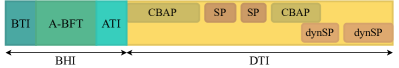
II The IEEE 802.11ad Beacon Interval
The IEEE 802.11ad standard divides time into Beacon Intervals (BIs) [19]. A BI may take up to , although is most commonly chosen [20]. The BI structure, illustrated in Figure 1, is divided into two parts: (1) the Beacon Header Interval (BHI), used for control traffic including association, beamforming and synchronisation, and (2) the Data Transmission Interval (DTI), where Stations (STAs) may transmit data according to some channel access method. This section covers the internals of these intervals, focusing on their implications in terms of latency.
II-A Beacon Header Interval
Compared to similar intervals in other Wi-Fi standards, the BHI is rather long and complex. This is largely due to high path loss experienced in the mmWave range. Due to legal power emission limits and energy usage concerns, robust mmWave links can only be achieved by focusing transmit power in a directional beam, meaning omnidirectional transmission is not feasible. All reachable directions from a STA are subdivided into pre-defined sectors, and reaching all directions requires sequential transmissions for all sectors.
At the start of the BHI, in the Beacon Transmission Interval (BTI), the Access Point (AP) may transmit Beacon Frames (BFs), informing any STA of its existence, its capabilities, and the specific structure of the remainder of the BI. BFs use the lowest Modulation and Coding Scheme (MCS), lengthening transmission. Next, in the Association Beamforming Training (A-BFT) phase, STAs may associate to the AP, and exchange frames with the AP in the beamforming process, in which the optimal sector is selected.
The A-BFT phase is divided into several slots, of which STAs pick one at random in a contention-based approach. Finally, in the Announcement Transmission Interval (ATI), the AP can exchange management information with already associated STAs through a unicast, higher-MCS request-response mechanism, which is considerably more spectrally efficient than sending BFs [20].
II-B Data Transmission Interval
The transmission of actual data (e.g., video content) occurs during the DTI. Channel access can be organised with a contention-based approach, using time division with a predefined schedule, or through polling. BFs contain an Extended Schedule, which indicates how the following DTI is organised. It contains a number of non-overlapping allocations, each assigned one method of channel access. Each allocation can be further subdivided into periods, with each period being equally spaced and equally sized, and periods of different allocations possibly being interleaved.
II-B1 Contention-Based Access Period
The Contention-Based Access Period (CBAP) is the simplest type of channel access in IEEE 802.11ad. During a CBAP, the well-known Enhanced Distributed Channel Access (EDCA) algorithm is applied. All incoming data traffic is assigned to one of four Access Categories (ACs), each with their own queue, according to latency requirements. Once the medium is sensed to be free for one Arbitration Interframe Space (AIFS) (of AC-dependent duration), a countdown is initialised randomly to an integer between 0 and (again AC-dependent). The station may commence transmission once this countdown, ticking down once per slot, reaches 0. Once the STA acquires the medium this way, it is granted a Transmit Opportunity (TXOP) of pre-defined, AC-dependent, length, during which it may continue transmitting frames of the same AC, each separated by 1 Short Interframe Space (SIFS). When the Extended Schedule is empty, the entire DTI may be set to one large CBAP through the CBAP-only flag in the BF.
II-B2 Service Period
The Service Period (SP) is a time division approach. For each SP, a pair of STAs are appointed as sender and receiver. During the SP, the sender has exclusive, uninterrupted access to the medium, but may only send to the configured receiver. If the sender determines that it no longer requires the remainder of its SP, it may relinquish the remaining time to the receiver or to the AP.
II-B3 Dynamic Allocation of Service Periods
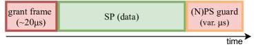
In case of bursty, non-periodic traffic patterns, the SP mechanism is far from optimal. It is therefore also possible to create SPs dynamically, based on demand, during the DTI. These dynamic Service Periods (dynSPs) are announced by sending Grant frames, optionally preceded by the AP polling STAs for grant requests. These Grant frames can be sent during CBAP or SP allocations, and a dynSP may overlap with or exceed the allocation during which it was announced. DynSPs too can be truncated.
III IEEE 802.11ad for Low Latency Traffic
The exact organisation of the BI has severe implications on latency-sensitive traffic, such as in live VR. Both the BHI and DTI need to be carefully organised to minimise their impact on the latency of content delivery.
III-A Beacon Header Interval Optimisation
The length of the BHI sets a lower bound on the attainable worst-case latency in the network, as no data transmission may occur during it. A relatively small 70 byte BF already takes upwards of to transmit per sector [19]. Furthermore, a single A-BFT slot of an 8-sector AP takes . Taking into account interframe spaces and propagation time, a BHI for 8 sectors with the default 8 A-BFT slots takes , with the optional ATI disabled entirely. This alone prevents the network from achieving sub-ms latencies consistently. Fortunately, there are a number of opportunities to decrease the BHI length. First, the BTI is not mandatory in every BHI, as the standard only requires it being present once every 15 BIs. However, the AP is required to send a BF on each sector at least once every 4 BIs. As such, the AP can rotate through sectors between BTIs, ideally dividing the number of BFs by 4. Next, the A-BFT is also required only once per 15 BIs, and its number of slots can be as low as 1. Lowering the number of slots only impacts performance when regular beamforming is needed due to STA mobility or environment dynamics, which are out of scope in this work. Overall, these two improvements reduce the worst-case BHI duration of an 8-sector AP to , including of interframe spaces.
This BHI configuration has a number of side-effects. First, STAs will, by design, no longer receive a BF for every BI. For such BIs without a BF, the STA does not know which allocations were assigned within the DTI. However, to alleviate this issue, allocations can be marked Pseudo-Static (PS). These allocations are assumed to reoccur for 4 BIs, starting from the one its allocation was received in, each time at the same offset from the start of the BI. A DTI-spanning CBAP allocation, indicated through the CBAP-only flag, is also considered to be PS. As such, the reduced number of BFs has no effect on STAs’ ability to participate in data transfer during PS allocations, as long as no BFs are lost.
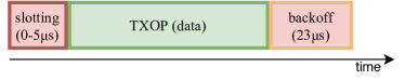
III-B Data Transmission Interval Optimisation
All three types of channel access incur their own set of overheads, summarised in Figure 2. An obvious overhead of CBAP is the time spent in the channel sensing and the backoff periods before transmission is allowed. However, a STA may enter its backoff period for an AC even if no frames are currently queued for it. Once the backoff timer expires, the system enters a post-backoff state [21]. If, within this state, a frame arrives in the queue, transmission may begin at the start of the next backoff slot. With optimal settings and no competing STAs, the post-backoff state can be reached after observing the medium for, at most, .
Next, by making sure the TXOP limit is configured to be sufficient to transmit a full VF, only a single TXOP is needed for each VF. An overdimensioned TXOP limit has no negative side effects, as the sender can end the TXOP early simply by refraining from sending any more data.
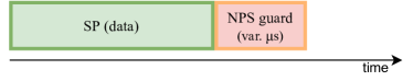
For a scheduled SP-based system, no slotting overhead exists. However, tight synchronisation between the content server and AP is crucial. The AP must be aware of the video streams’ characteristics for SP scheduling, and SPs have to be shifted every BI to maintain synchronisation, meaning only Nonpseudo-Static (NPS) allocations can be used. With dynSPs, Grant frames add latency. The allocations for Grant frame transmission may be PS or NPS.
Another important latency factor is the use of guard times. A guard time must occur between any two subsequent allocations, and ahead of a CBAP-only allocation. As each STA’s clock may drift from the clock provided in the BFs, these guard times are necessary to ensure that adjacent allocations’ transmissions do not overlap. The minimum guard time , in , between allocations and is defined as:
| (1) |
where is 5 for PS allocations and 1 otherwise, is the maximum allowable clock drift, defined as , is the time passed since the latest synchronisation (or the BI length for PS allocations), the SIFS is , and is the air propagation time between two STAs, defined as . Guard times for PS allocations are significantly longer than for NPS allocations, although the exclusive use of PS allocations does shorten the BHI. In addition, guard times grow as the BI length increases. The precise impact is investigated in the following section.
IV Theoretical Analysis
In this section, we apply our findings in a mmWave multi-user VR environment, determining its maximum attainable per-user bitrate.
IV-A Virtual Reality Setup
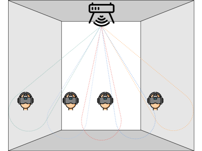
We consider an obstacle-free room with one or more HMD-wearing users on the ground, and a single ceiling-mounted central AP, as shown in Figure 3. In this initial work, we assume that the AP placement guarantees an unobstructed line of sight with each HMD and we do not explicitly account for significant user mobility, but note that some user movements can occur. As long as the HMD remains within one sector, mobility should not affect connectivity. Current-day IEEE 802.11ad APs are limited to 2-8 relatively wide sectors. Beamforming is assumed to have been performed in advance, and its optimisation is considered out of scope in this work. All devices use the Single Carrier (SC) PHY at the maximum MCS 12. The AP is directly connected to a content server (possibly a Mobile Edge Cloud) responsible for VF generation and processing for all users. VFs are generated in real-time, at a fixed framerate, and immediately transmitted to the users one-by-one. Network-wise, the video content is streamed over UDP, chosen for its low overhead. At the MAC layer, the AP aggregates data using Aggregated MAC Protocol Data Units (A-MPDUs), as this again lowers overhead. One such A-MPDU can fit at most 32 data units, each containing of application data (plus of headers up to the transport layer). We only consider downstream traffic, but note that our findings are easily extended to also consider some upstream traffic, such as viewing direction, voice, and user inputs.
IV-B Abstractions
Given a system with HMDs running at a refresh rate and a maximum allowed VF transmission latency , our goal is to find the maximum attainable video bitrate that will not violate the VF transmission latency. To compare latency under different channel access methods, we abstract all types of latencies that may delay VF delivery into one of three classes. First is the interBI latency, which only occurs once per BI, at its start. This relatively rare but long latency block comprises the BHI, any guard time preceding the first allocation in the BI, and any latency before the AP can access the medium during this allocation, induced by the channel access method. Next is the regular interVF latency, occurring between any two subsequent VF transmissions (unless overridden by interBI latency) and immediately following the previous transmission. This includes guard times between allocations and, again, any latency before the AP can access the medium during the allocation, induced by the channel access method. Finally, access latency occurs between a VF’s arrival at the AP and the start of its transmission. This comprises any latency induced by the channel access method, occurring regardless of the observed medium state before the VF arrived. This may include overheads due to slotting, and control overhead that must occur just before data transmission. Note that any channel access method-agnostic overheads, such as PHY/MAC headers and RTS/CTS overheads, are accounted for in Section IV-E.
We divide time into VF intervals of length , such that, for each HMD, exactly one VF is generated per VF interval. The VF interval consists of latency blocks (at most 1 interBI, and or interVF) and equally-sized VF blocks, each available for transmission to one HMD. For convenience, we define access latency to be part of the VF block. By analysing how much time of the VF interval is lost to these types of latencies, the time available for VF transmission for each HMD can easily be calculated. Note that only the worst case is considered; often the interBI latency will not be present, replacing it with the significantly shorter interVF latency.
IV-C Coordination Levels

Depending on the exact physical setup and customisability of the AP, different levels of coordination may be feasible. We consider two cases: (1) tight coordination between content server and AP, with the content server being BI-aware, and (2) coordination between the different video streams at the AP.
IV-C1 BI coordination
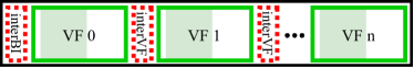
In this case, the content server is aware of the general IEEE 802.11ad BI structure, and carefully schedules VF generation to not overlap with any latency blocks. Without loss of generality, we assume that each interBI latency block occurs at the start of a VF interval. The full VF interval is illustrated in Fig. 4. After determining interBI latency and interVF latency , the maximum length of a VF block is easily calculated:
| (2) |
Access latency and maximum allowed latency however limit how much of the VF block may be used for data transmission. We therefore divide into three parts: an access latency part of length , a usable part of length , and an unused end buffer of length . These lengths are calculated as , and , such that .
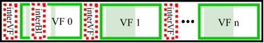
IV-C2 Video coordination
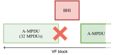
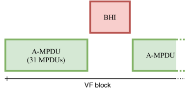
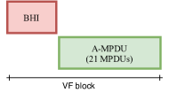
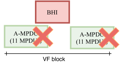
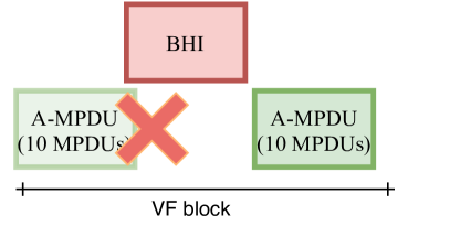
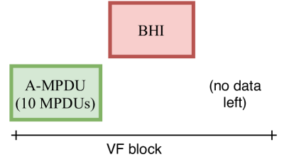
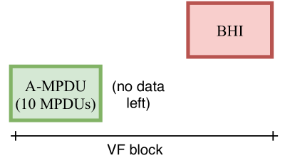
In the second case, the content server no longer actively attempts to avoid interBI latency blocks. Instead, it simply divides VF blocks evenly across the VF interval. While the content server still leaves room for the interVF latency block (whose position is decided by the preceding VF block), a VF block may now overlap with an interBI latency block. As a result, the transmission schedule as intended by the content server, may differ from that actually used at the AP. When an interBI latency block is inserted during VF transmission, the AP may slice the VF block in two, such that . Fig. 5a and 5b show the schedule as intended at the content server, and executed at the AP, respectively. In the worst case, the interBI latency block is scheduled such that the first part of the VF block is just too short to send the first A-MPDU. Unless the AP can dynamically adapt its maximum A-MPDU size given the time remaining in the current allocation (which would be challenging to implement, and therefore unlikely to be supported by COTS hardware), cannot actually be used for data transmission if it is shorter than , the time needed to successfully complete a full A-MPDU transmission (calculated in Section IV-E). As long as 1 VF requires at least 1 full A-MPDU, this worst-case remains unused, and all data transmission only occurs in . If instead a single non-full A-MPDU suffices, it could be sent in either or , whichever is biggest, meaning the worst case occurs when the two are equal. Figure 6 and Figure 7 illustrate these two cases. The actually usable in both cases can be defined as:
| (3) |
| (4) |
IV-D VF Block Length
We now calculate VF block length for each combination of coordination assumption and channel access method. Recall that Figure 4 and 5 summarise the VF interval structure, while Figure 2 details the VF block structure for each channel access method, with access latency in red and interVF latency in orange. For every method with PS allocations, each sector sees one BF once every four BIs, while with NPS allocations each sector receives a BF every BI. The full BHI for 8 sectors has a fixed base transmission time of (PS only) or (incl. NPS), increased by per BF for each allocation in the Extended Schedule. The guard time as defined in (1) occurs between every pair of adjacent allocations and before a CBAP-only allocation. Channel sensing and the backoff period between two TXOPs amount to at most . Finally, the access latency comprises waiting at most for the next slot start in CBAP allocations, the transmission of a Grant frame for dynSPs, and is zero in all other cases. Table I shows all latencies, assuming an 8 sector AP and a BI length equal to the VF interval length. The two components of the BHI duration are listed separately, between brackets. Given the interBI and interVF latency, we calculate for 1, 2, 4 and 8 HMDs, with refresh rate , shown in Table II. As long as , the value of has a direct, significant influence on the attainable video bitrate, meaning any hardware or software improvements lowering other aspects of MTP latency can indirectly increase this bitrate.
| interBI | interVF | access | |
|---|---|---|---|
| CBAP-only | + 5 | 23 | 5 |
| PS CBAP | 23 | 5 | |
| NPS CBAP | 23 | 5 | |
| NPS SP | 4 | 0 | |
| PS dynSP | 5 | 19.8 | |
| NPS dynSP | 4 | 19.8 |
| 1 HMD | 2 HMDs | 4 HMDs | 8 HMDs | |
|---|---|---|---|---|
| CBAP-only | 8.079 | 4.026 | 1.999 | 0.985 |
| PS CBAP | 8.074 | 4.023 | 1.998 | 0.985 |
| NPS CBAP | 7.840 | 3.906 | 1.939 | 0.956 |
| NPS SP | 7.840 | 3.898 | 1.927 | 0.942 |
| PS dynSP | 8.074 | 4.035 | 2.015 | 1.005 |
| NPS dynSP | 7.840 | 3.918 | 1.957 | 0.977 |
IV-E Attainable Bitrate
Given the latency block lengths for a configuration, we can calculate , the time available for data transmission, and convert this to a video bitrate. The AP sends a number of A-MPDUs, each requiring only 1 PHY header, and acknowledged with a single Block ACK. The PHY sends 1 chip per , translating to at MCS 12 [19]. As such, transmission of 1 A-MPDU consists of, in order: 1 PHY preamble + header ( chips), 32 MPDUs (each ), 1 SIFS, 1 PHY preamble + header, 1 Block ACK (), 1 SIFS. The duration of one A-MPDU then becomes:
where is the preamble and PHY header overhead, and and are the MAC-level transmission times of a Block ACK and an MPDU, respectively. The number of full A-MPDUs that can be sent in 1 then becomes
and finally one more non-full A-MPDU of MPDUs can be sent, if :
The total attainable size for one VF then becomes . This is easily translated to video bitrate, given the refresh rate. Table III shows the attainable bitrate for 1 and 8 HMDs, given the latency block lengths in Table I, with refresh rate =. The impact of adding more HMDs is limited with coordination; the additional HMDs mainly reduce . Overall, PS approaches are more viable, as their BHI is significantly shorter, while their higher guard times are barely noticeable. Guard times scale with BI length, which we chose to be only . Conveniently, the top-performing PS CBAP and CBAP-only approaches are also the simplest to implement, and therefore most likely to be supported by COTS hardware.
Finally, note that RTS/CTS could easily be taken into consideration by subtracting its overhead from . Similarly, upstream traffic could easily be sent in the end buffer, as the STA can be granted channel access in the TXOP/SP through the Reverse Direction protocol [19]. If the end buffer does not suffice, could again be reduced.
| BI coordination | Video coordination | |||||
|---|---|---|---|---|---|---|
| 1 HMD | 8 HMDs | 1 HMD | 8 HMDs | |||
| 1ms | 5ms | 1ms | 1ms | 5ms | 1ms | |
| CBAP-only | 505 | 2541 | 498 | 188 | 2187 | 188 |
| PS CBAP | 505 | 2541 | 498 | 188 | 2180 | 180 |
| NPS CBAP | 505 | 2541 | 484 | 123 | 2064 | 115 |
| NPS SP | 505 | 2548 | 476 | 115 | 2050 | 29 |
| PS dynSP | 498 | 2541 | 498 | 180 | 2165 | 180 |
| NPS dynSP | 498 | 2541 | 484 | 130 | 2072 | 123 |
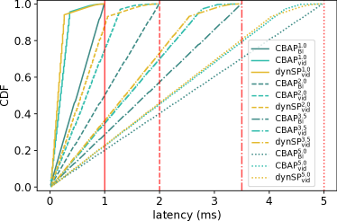
V Validation
We now validate our theoretical results using the IEEE 802.11ad module [22, 23] of the ns-3 simulator [24]. We evaluate three combinations of channel access method and coordination level, repeating the experiments for four different values: , , and . The used bitrates are partially found in Table III, the others can be calculated with the formulas presented. We measure the latency of each VF-carrying packet (between the end of VF generation and delivery at the HMD), and show the Cumulative Distribution Function (CDF) for all experiments in Fig. 8. We first validate the BI-coordinated CBAP-only approach. We implement the coordination by slightly increasing the refresh rate, such that the BI length is a multiple of the VF interval length, and shift the maximum attainable bitrates accordingly. For this single-HMD experiment, labelled CBAPBI, latency approaches in each case, but never exceeds it. The highest latencies observed are , , and .
Second, we validate the video coordination approach. As in the previous case, all packets in this experiment, labelled CBAPvid, arrive on time as intended, with highest latencies , , and . Notice that the long tail of the CDF is indicative of the BHI, configured to occur every , occasionally overlapping with VF blocks.
Third, we repeat this experiment with dynSPs using PS allocations, labelled dynSPvid, again reaching the same conclusion, with highest latencies , , and . This experiment exhibits an even longer tail, as its BHI is significantly longer. As a final experiment, we validate our analysis for multi-HMD setups by repeating the CBAP1.0vid case for 8 HMDs, which, as expected, shows no difference in latency compared to the single-HMD case.
VI Conclusions and Future Work
In this work, we presented the first comparison of IEEE 802.11ad’s different channel access methods with regards to latency-sensitive live VR traffic. Specifically, we provided a theoretical framework for deriving the maximum attainable bitrates within given latency bounds for each access method. Through this framework, we demonstrated the severe impact of beacon transmission on the attainable video bitrate. In addition, we showed that the use of Pseudo-Static (PS) allocations, as well as tight coordination between content server and AP, can significantly improve said bitrates.
Entry-level HMDs, with two 2K displays, require a throughput of [6], which we have demonstrated to be attainable at a transmission latency of only , with any channel access method and for at least 8 HMDs, assuming the frames of the different video streams are properly interleaved. If the content server is BI-aware, at least 8 advanced HMDs, featuring 4K displays and each requiring , can be supported with a transmission latency of . Thus, our work suggests IEEE 802.11ad as a viable candidate in supporting live VR applications. Future ultimate VR [25], featuring 8K displays and requiring can only be supported at a transmission latency of . Lowering this to will require the additional throughput offered by IEEE 802.11ay. In our future work, we will explore the limits of live VR over IEEE 802.11ay, and characterise the effects of interference and HMD mobility on achievable bitrates and latency guarantees.
Acknowledgment
The work of Jakob Struye was supported by the Research Foundation - Flanders (FWO): PhD Fellowship 1SB0719N. The work of Filip Lemic was supported by the EU Marie Skłodowska- Curie Actions Individual Fellowships (MSCA-IF) project Scalable Localization-enabled In-body Terahertz Nanonetwork (SCaLeITN), grant nr. 893760. In addition, this work received support from the University of Antwerp’s University Research Fund (BOF). The authors thank Hany Assasa for support on the ns-3 IEEE 802.11ad module.
References
- [1] D. King, S. Tee, L. Falconer, C. Angell, D. Holley, and A. Mills, “Virtual health education: Scaling practice to transform student learning: Using virtual reality learning environments in healthcare education to bridge the theory/practice gap and improve patient safety,” in Nurse Education Today, vol. 71, pp. 7–9, Dec. 2018.
- [2] K. Ahir, K. Govani, R. Gajera, and M. Shah, “Application on Virtual Reality for Enhanced Education Learning, Military Training and Sports,” in Augment Hum Res, vol. 5, no. 1, p. 7, Nov. 2019.
- [3] R. Yung, and C. Khoo-Lattimore,“New realities: a systematic literature review on virtual reality and augmented reality in tourism research,” in Current Issues in Tourism, vol. 22, no. 17, pp. 2056-2081, 2019.
- [4] E. Bastug, M. Bennis, M. Medard, and M. Debbah, “Toward Interconnected Virtual Reality: Opportunities, Challenges, and Enablers,” in IEEE Communications Magazine, vol. 55, no. 6, pp. 110–117, Jun. 2017.
- [5] M. S. Elbamby, C. Perfecto, M. Bennis, and K. Doppler, “Toward Low-Latency and Ultra-Reliable Virtual Reality,” in IEEE Network, vol. 32, no. 2, pp. 78–84, Mar. 2018.
- [6] S. Mangiante, G. Klas, A. Navon, Z. GuanHua, J. Ran, and M. D. Silva, “VR is on the Edge: How to Deliver 360° Videos in Mobile Networks,” in Proceedings of the Workshop on Virtual Reality and Augmented Reality Network, Los Angeles, CA, USA, pp. 30–35, Aug. 2017.
- [7] R. Ford, M. Zhang, M. Mezzavilla, S. Dutta, S. Rangan, and M. Zorzi, “Achieving Ultra-Low Latency in 5G Millimeter Wave Cellular Networks,” in IEEE Communications Magazine, vol. 55, no. 3, pp. 196–203, Mar. 2017.
- [8] T. Levanen, J. Pirskanen, and M. Valkama, “Radio interface design for ultra-low latency millimeter-wave communications in 5G Era,” in 2014 IEEE Globecom Workshops (GC Wkshps), pp. 1420–1426, Dec. 2014.
- [9] G. Yang, M. Xiao, and H. V. Poor, “Low-Latency Millimeter-Wave Communications: Traffic Dispersion or Network Densification?,” in IEEE Transactions on Communications, vol. 66, no. 8, pp. 3526–3539, Aug. 2018.
- [10] N. Mehrnia and S. C. Ergen, “Power Efficient Beam-Forming Algorithm for Ultra-Reliable Low Latency Millimeter-Wave Communications,” in 2019 IEEE International Black Sea Conference on Communications and Networking (BlackSeaCom), pp. 1–5, Jun. 2019.
- [11] C. Hemanth and T. G. Venkatesh, “Performance Analysis of Service Periods (SP) of the IEEE 802.11ad Hybrid MAC Protocol,” in IEEE Transactions on Mobile Computing, vol. 15, no. 5, pp. 1224–1236, May 2016.
- [12] C. Pielli, T. Ropitault, N. Golmie, and M. Zorzi, “An Analytical Model for CBAP Allocations in IEEE 802.11ad,” unpublished.
- [13] M. P. R. S. Kiran and P. Rajalakshmi, “Saturated Throughput Analysis of IEEE 802.11ad EDCA For High Data Rate 5G-IoT Applications,” in IEEE Transactions on Vehicular Technology, vol. 68, no. 5, pp. 4774–4785, May 2019.
- [14] A. Zhou, L. Wu, S. Xu, H. Ma, T. Wei and X. Zhang, “Following the Shadow: Agile 3-D Beam-Steering for 60 GHz Wireless Networks,” in IEEE INFOCOM 2018 - IEEE Conference on Computer Communications, pp. 2375-2383, 2018.
- [15] O. Abari, D. Bharadia, A. Duffield, and D. Katabi. “Enabling high-quality untethered virtual reality,” in 14th USENIX Symposium on Networked Systems Design and Implementation, pp. 531-544. 2017.
- [16] T. T. Le, D. V. Nguyen and E. Ryu, “Computing Offloading Over mmWave for Mobile VR: Make 360 Video Streaming Alive,” in IEEE Access, vol. 6, pp. 66576-66589, 2018.
- [17] W. Na, N.N. Dao, J. Kim, E.S. Ryu, and S. Cho, “Simulation and measurement: Feasibility study of Tactile Internet applications for mmWave virtual reality,” in ETRI Journal 42, no. 2, pp. 163-174, Jan. 2020.
- [18] C. Chen, O. Kedem, C. R. C. M. da Silva and C. Cordeiro, “Millemeter-Wave Fixed Wireless Access Using IEEE 802.11ay,” in IEEE Communications Magazine, vol. 57, no. 12, pp. 98-104, Dec. 2019.
- [19] “IEEE Standard for Information technology—Telecommunications and information exchange between systems Local and metropolitan area networks—Specific requirements - Part 11: Wireless LAN Medium Access Control (MAC) and Physical Layer (PHY) Specifications,” IEEE Std. no. 802.11-2016, Dec. 2016.
- [20] T. Nitsche, C. Cordeiro, A. B. Flores, E. W. Knightly, E. Perahia, and J. C. Widmer, “IEEE 802.11ad: directional 60 GHz communication for multi-Gigabit-per-second Wi-Fi [Invited Paper],” in IEEE Communications Magazine, vol. 52, no. 12, pp. 132–141, Dec. 2014.
- [21] P. E. Engelstad and O. N. Osterbo, “Analysis of the Total Delay of IEEE 802.11e EDCA and 802.11 DCF,” in 2006 IEEE International Conference on Communications, vol. 2, pp. 552–559, Jun. 2006.
- [22] H. Assasa and J. Widmer, “Implementation and Evaluation of a WLAN IEEE 802.11ad Model in ns-3,” in Proceedings of the Workshop on ns-3, Seattle, WA, USA, pp. 57–64, Jun. 2016.
- [23] H. Assasa and J. Widmer, “Extending the IEEE 802.11Ad Model: Scheduled Access, Spatial Reuse, Clustering, and Relaying,” in Proceedings of the Workshop on Ns-3, New York, NY, USA, pp. 39–46, 2017.
- [24] G. F. Riley and T. R. Henderson, “The ns-3 Network Simulator,” in Modeling and Tools for Network Simulation, K. Wehrle, M. Güneş, and J. Gross, Eds. Berlin, Heidelberg: Springer, 2010.
- [25] H. Zhang, A. Elmokashfi, Z. Yang, and P. Mohapatra, “Wireless Access to Ultimate Virtual Reality 360-Degree Video At Home,” in Proceedings of the International Conference on Internet of Things Design and Implementation, pp. 271-272, 2019.