Optical spatial differentiation with suspended subwavelength gratings
Abstract
We demonstrate first- and second-order spatial differentiation of an optical beam transverse profile using thin suspended subwavelength gratings. Highly reflective one-dimensional gratings are patterned on suspended 200 nm-thick silicon nitride membranes using Electron Beam Lithography and plasma etching. The optical transmission of these gratings, designed for illumination with either TM or TE polarized light, are experimentally measured under normal and oblique incidence and found to be in excellent agreement with the predictions of an analytical coupled-mode model as well as Rigorous Coupled Wave Analysis numerical simulations. High quality first- and second-order spatial differentiation of a Gaussian beam are observed in transmission at oblique and normal incidence, respectively. Such easy-to-fabricate, ultrathin and loss-free optical components may be attractive for beam shaping and optical information processing and computing.
I Introduction
The use of metamaterials and subwavelength-structured devices enables the realization of compact and efficient optical components with tailored optical properties. Of particular interest for all-optical information processing are devices performing spatial or temporal transformations of optical signals. In the spatial domain such ultracompact devices can substantially reduce the footprint of bulky components, such as lenses and filters, and enable integration into complex optical systems.
Spatial differentiation and integration have been proposed with metasurface-based components Silva2014 ; Pors2015 , as well as with resonant diffractive devices Doskolovich2014 ; Golovastikov2014 ; Bykov2014 ; Ruan2015 ; Youssefi2016 ; Hwang2016 ; Zhu2017 ; Zangeneh2017 ; Zangeneh2018 ; Hwang2018 ; Guo2018 . Such diffractive resonant structures can be multilayered systems Doskolovich2014 ; Bykov2014 ; Ruan2015 ; Youssefi2016 ; Zhu2017 ; Zangeneh2017 ; Zangeneh2018 , plasmonic structures Hwang2016 ; Hwang2018 , subwavelength gratings Golovastikov2014 or photonic crystals Guo2018 .
Following the proposal of Doskolovich2014 , spatial differentiation was recently implemented with subwavelength TiO2 on quartz gratings Bykov2018 and Si on quartz high-contrast subwavelength gratings Dong2018 . There, first-order spatial differentiation of the transverse profile of a beam was obtained in transmission by illuminating the grating at oblique incidence at a specific wavelength, determined by the interference between the incident light and a guided-resonant mode in the grating. As pointed out in Bykov2018 ; Dong2018 , such subwavelength structures may be comparatively easier to design and fabricate than metasurfaces and do not require additional lens or filter to perform the required spatial transformations.
Building upon these advances, we demonstrate here both first- and second-order spatial differentiation of an optical beam transverse profile using thin (200 nm) silicon nitride suspended subwavelength gratings. We make use of the recently demonstrated recipe for directly patterning commercial high quality suspended Si3N4 films with one-dimensional subwavelength gratings Nair2019 . In contrast with Nair2019 , much larger gratings—(200 m)2 vs (50 m)2—are realized, allowing for operating with larger beams, thus minimizing focusing and finite size effects and thereby acheiving high reflectivity (¿95%) Parthenopoulos2020 . Gratings with different periods/fill factors are fabricated to observe TE or TM resonances in 920-960 nm range. Their transmission spectra under monochromatic illumination at different incidence angles are measured and resonances with different parity guided modes are observed. Very good agreement between the predictions of full Rigorous Coupled Wave Analysis simulations and the simple coupled-mode model of Bykov et al. Bykov2015 ; Bykov2017 is obtained. High quality first- and second-order spatial differentiation of a Gaussian beam transverse profile is observed at oblique and normal incidence, respectively, for either TM or TE incident polarized light.
Such easy-to-fabricate, ultrathin and loss-free components are attractive for beam shaping and optical information processing and computing and add to the panoply of applications of subwavelength grating-based devices Chang-Hasnain2012 ; Quaranta2018 . Moreover, they may enable new applications of suspended Si3N4 thin films, possessing both high optical and mechanical quality and which are widely used within optomechanics Thompson2008 ; Kemiktarak2012 ; Bui2012 ; Kemiktarak2012NJP ; Xuereb2012 ; Norte2016 ; Reinhardt2016 ; Li2016 ; Chen2017 ; Nair2017 ; Moura2018 ; Naesby2018 ; Gartner2018 ; Cernotik2019 ; Dantan2020 ; Manjeshwar2020 .
II Theoretical model and simulations
II.1 Coupled mode model
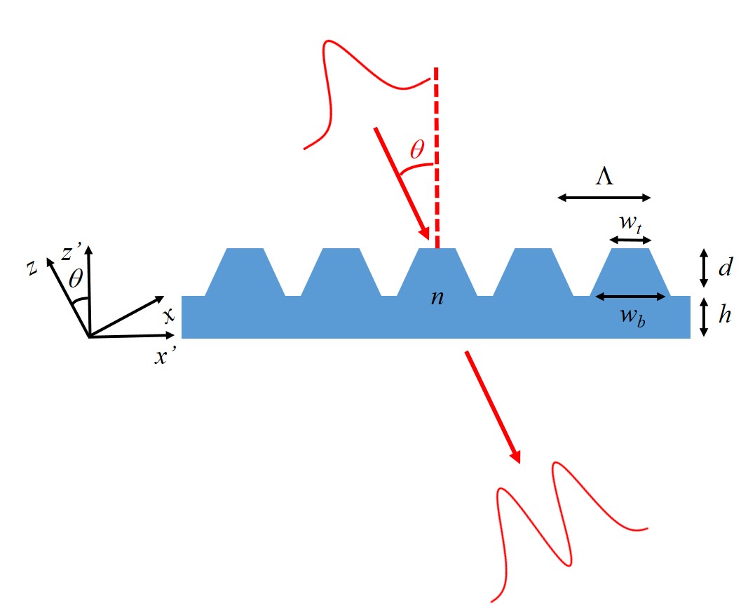
We follow Bykov et al.’s approach and notations Golovastikov2014 ; Bykov2018 and consider an infinite one-dimensional grating with period illuminated by a monochromatic light beam with wavelength and transverse profile amplitude (Fig. 1). The incident beam is linearly polarized in the -plane and its propagation direction makes an angle with the direction normal to the grating plane. Due to the subwavelength nature of the grating, the transmitted beam is in the zeroth diffraction order and its profile, denoted by , is obtained from that of the incident beam using a transfer function Golovastikov2014 ; Bykov2018
| (1) |
where is the free-space wave number and is the transmission coefficient of the grating, where is the component of the wave vector in the grating coordinate system (Fig. 1). An elegant coupled mode model was put forward by Bykov et al. in Bykov2017 to derive a generic approximate expression for this transmission coefficient, which, in the vicinity of the guided mode resonance and for small angles of incidence, reads
| (2) |
where is the light field frequency, being the speed of light, and , , , , and () are parameters depending on the grating geometry and refractive index.
Choosing , results in a vanishing transmission coefficient, . Assuming a weakly focused beam with similar spectral widths in the and directions and expanding the transmission coefficient in the vicinity of this point at lowest order in , yields
| (3) |
where can be obtained from the phenomenological parameters introduced in Eq. (2). Since, for a weakly focused beam, Eq. (1) becomes
| (4) |
choosing the angle of incidence such that allows for reexpressing the transfer function of the grating as that of a spatial differentiator
| (5) |
up to a proportionality constant .
At normal incidence (), the transfer function is not linear, but quadratic in . This can be exploited to perform a second order differentiation of the beam profile, as suggested in Doskolovich2014 and as demonstrated in Sec. IV.
II.2 RCWA simulations
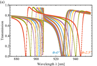
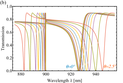
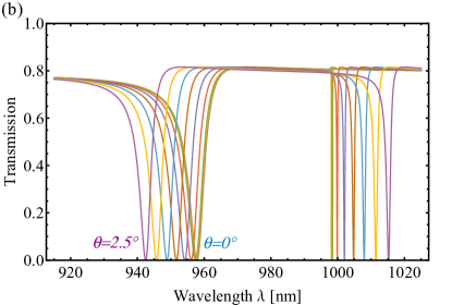
To illustrate the accuracy of this coupled mode model and prepare the ground for the experimental observations of the following sections, we numerically simulated the transmission spectra of infinite one-dimensional gratings with parameters similar to those whose fabrication will be detailed in Sec. III using full RCWA calculations MIST . We thus considered infinite lossless gratings made of silicon nitride (refractive index 2.0) and whose profile is shown in Fig. 1. The grating fingers are trapezoidal with top and bottom widths and , respectively, and have a height . The underlying silicon nitride layer has a thickness . We assume infinite plane wave illumination with light impinging on the grating, as depicted in Fig. 1, and with either TM or TE polarization. Figures 2 and 3 show the simulated (intensity) transmission spectra for different incidence angles of two gratings designed to observe guided mode resonances in the range 915-975 nm and whose fabrication and characterization are detailed in Sec. III. The simulated spectra are calculated using the MIST software MIST , discretizing the medium in 20 layers and using a 25 mode basis. The parameters of the grating whose spectra are shown in Fig. 2 are nm, nm, nm, nm and nm and the light polarization is TM, while those of the grating whose spectra are shown in Fig. 3 are nm, nm, nm, nm and nm and the light polarization is TE. The essential difference between these two gratings is thus a shorter period for the ”TE grating” (and thereby a higher fill factor) as compared to the ”TM grating”. As discussed in the next section, this choice is merely motivated by the possibility of being able to observe the TM or TE resonances within the available tuning range of the laser used for characterizing the samples.
These spectra can be straightforwardly interpreted in terms of the parameters of the coupled mode model introduced in the previous section. Indeed, rewriting in the small incidence approximation yields a transmission coefficient equal to
| (6) |
As shown in Bykov2015 ; Bykov2017 , , and are real parameters for a lossless grating. thus represents the light frequency at which the transmission vanishes at normal incidence. represents the resonance frequency of the odd guided mode. is a complex number, which we choose to write as , where is the resonance frequency of the even guided mode and its width. is a constant depending on the mode group velocity and determines the shifts of the guided mode resonances with the incidence angle. is the intensity transmission coefficient far from the resonances. Note that, at normal incidence (), the transmission coefficient simply takes the well-known form
| (7) |
which yields a single Fano resonance in the transmission spectrum, as the incident wavefront symmetry only allows for exciting the even guided mode at normal incidence Fan2002 ; Fan2003 ; Bykov2015 ; Bykov2017 . At oblique incidence, the odd guided mode can be excited and a second Fano resonance appears. It is easy to see from Eq. (6) that both resonances are shifted further apart—quadratically with —as the incidence angle is increased.
The results of fits of the simulated spectra of Figs. 2(a) and 3(a) to the coupled model [Eq. (6)] are shown in Figs. 2(b) and 3(b), respectively. For completeness, fitting first the normal incidence spectrum and subsequently performing a global fit to the various incidence angle spectra yields the following parameters (expressed in wavelength units): nm, nm, nm, nm, (nm.deg)-1 and for the ”TM grating” of Fig. 2, and nm, nm, nm, nm, (nm.deg)-1 and for the ”TE grating” of Fig. 3. The shapes and widths of the resonances, as well as the magnitude of the resonance shifts with the incidence angle, are roughly similar for both gratings, but, since for the TM grating, the even mode resonance is shifted towards higher wavelengths, whereas the opposite occurs for the TE grating.
A very good overall agreement is observed, showing that the coupled mode model captures well the salient features of the interferences between the incident and the guided modes. Such an agreement was already evidenced in Bykov2015 in the case of a deeply subwavelength guided-mode resonant filter; remarkably, it also holds in the case of the gratings studied here, which operate in an intermediate regime between that of deep, high-contrast gratings and that of shallow, weakly modulated subwavelength gratings.
III Fabrication and characterization
To fabricate the subwavelength gratings, a recipe similar to that demonstrated in Nair2019 was used. We start with commercial (Norcada Inc., Canada), high tensile stress ( GPa), stochiometric silicon nitride suspended thin films. The silicon nitride films are 200 nm-thick and deposited on a 5 mm-square, 200 m-thick silicon frame. The lateral dimension of the suspended square membrane is 500 m and the lateral size of the patterned grating area is 200 m.
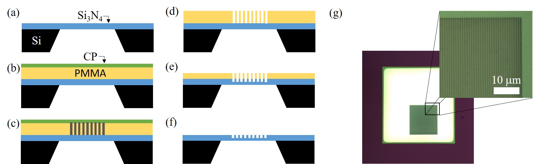
The subwavelength grating structures are realized following the steps depicted in Fig. 4. After oxygen plasma cleaning the samples are spin-coated with a 550 nm-thick layer of 7% 950k PMMA and a 50 nm-thick conductive polymer (SX-AR-PC 5000). A square grating mask is written by EBL (dose 310 C/cm2, acceleration voltage 30 kV). The conductive polymer layer is subsequently removed by immersion in deionized water and the PMMA resist is developed in a solution of 3:7 H2O:IPA for 1 min and stopped by direct dipping into pure IPA for 30 s. The sample is then etched in a STS Pegasus ICP DRIE system using reactive ion etching with C4F8 (flow rate 59 sccm) and SF6 (flow rate 36 sccm) for 95 s at an rf power 800 W. The PMMA layer is removed in acetone and the sample is cleaned and dried with N2.
An optical microscope picture of the obtained ”TM grating” structure is shown in Fig. 4(g). Homogenous grating structures with trapezoidal fingers with a depth corresponding to roughly half the slab thickness are obtained. Instead of the (destructive) Focused Ion Beam cutting method used in Nair2019 , the transverse profile of the subwavelength gratings is noninvasively determined here using Atomic Force Microscopy scans, allowing us to accurately extract the geometrical grating parameters (period, finger top and bottom widths, finger depth) Darki2020 . The (unpatterned) thin film refractive index and thickness are determined independently by ellipsometry or white light interferometry Nair2017 . This characterization provides the input parameters used in the simulations of the previous section.
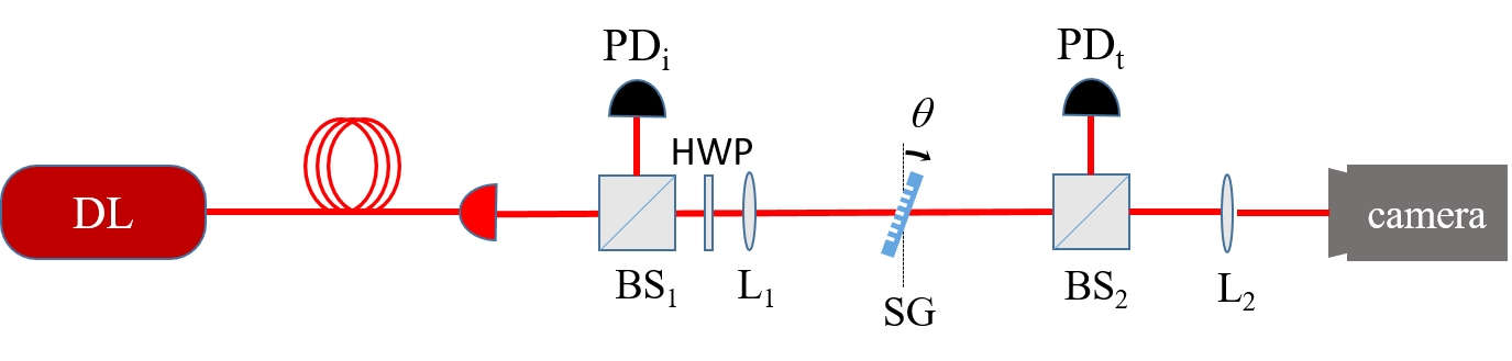
In order to characterize the optical transmission properties of the gratings under monochromatic illumination, monochromatic light from a tunable diode laser (Toptica DLC Pro 915-985 nm) is coupled into a single-mode polarization maintaining fiber and approximately half of the light exiting the fiber is weakly focused using an achromatic 75 mm-focal length doublet (L1) onto the membrane which rests on a mount with adjustable tilt. The polarization of the incident light is set by an achromatic halfwave plate (Thorlabs AHWP05M-980). Part of the transmitted light is sent to a photodetector using a beamsplitter (BS2), while the light reflected by the second beamsplitter is collected by a 75 mm-focal length lens (L2) and a CMOS camera (Thorlabs DCC1545) with an Edmund Optics 83-891 objective, in order to provide an image of the transverse profile of the beam at the membrane with a magnification of approximately 3. The transmitted signal measured by the photodetector (PD), in combination with the monitored incident power (PD), is used to determine the normalized transmission of the sample, by performing scans of the laser wavelength with and without membrane.
The larger size (and high quality) of the subwavelength grating structures realized—(200 m)2 versus (50 m)2 in Nair2019 —allows for reducing collimation and finite size effects, as compared to Nair2019 , by operating with large beam waists ( m beam waist radius here) and thereby achieving high reflectivity (¿95%) Parthenopoulos2020 .
IV Spatial differentiation
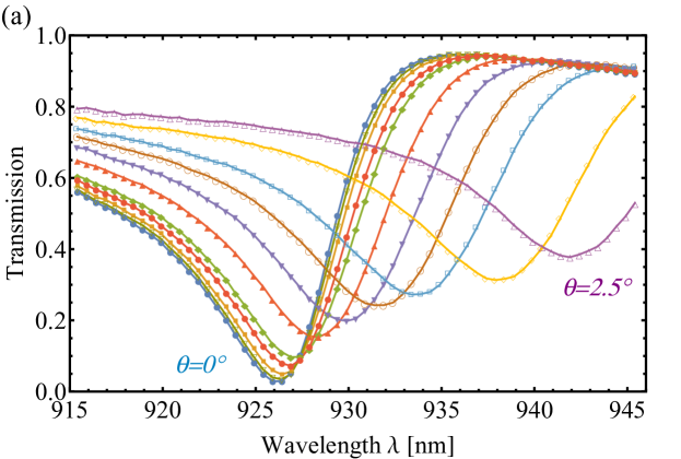
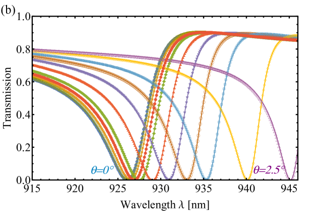
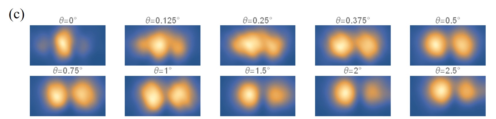
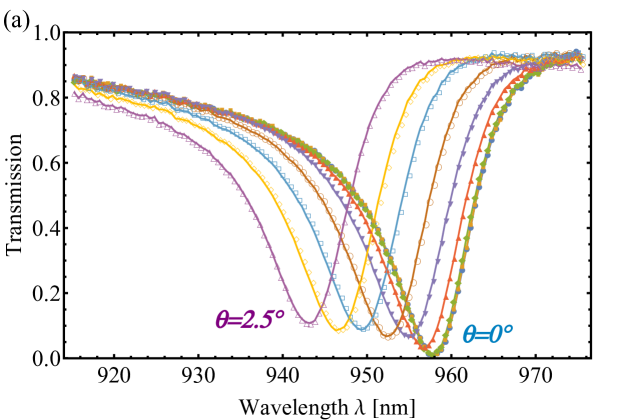
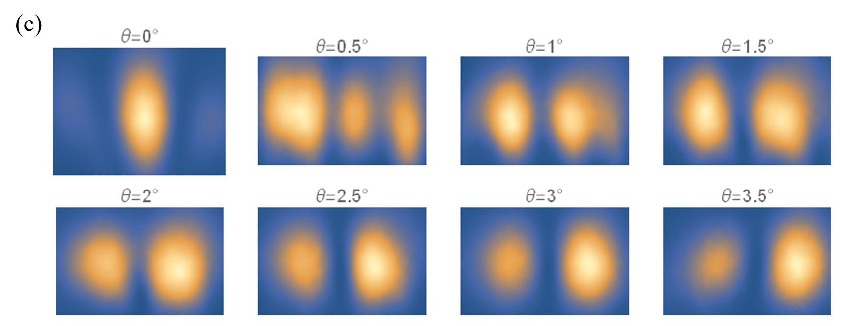
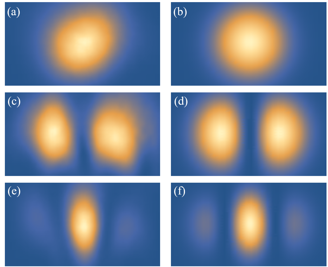
We now investigate the spatial differentiation of a Gaussian beam using the ”TM grating” fabricated in the previous section. The beam exiting the single mode fiber is to a very good approximation in a fundamental Hermite-Gauss mode. Figure 7(a) shows the transverse profile of the incident beam imaged at the membrane position, while Fig. 7(c) shows the result of a fit to a Gaussian profile , yielding a fit coefficient of 0.996. Figures 6(a) and (c) show the transmission spectra through the grating at various incidence angles between and , as well images of the transverse profile of the transmitted beams taken at the corresponding minimum transmission wavelength.
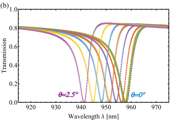
At normal incidence a single Fano resonance is observed at 925.8 nm, where the minimum transmission is 3.4%). At oblique incidence, the Fano resonance is shifted towards higher wavelengths, as expected from the theoretical predictions; the corresponding simulated spectra of Fig. 2(a) are shown again in Fig. 6(b) for reference. As the incidence angle increases the width of the resonance and the minimum transmission increase as well, due to collimation effects (which are not taken into account in the RCWA simulations assuming plane wave illumination).
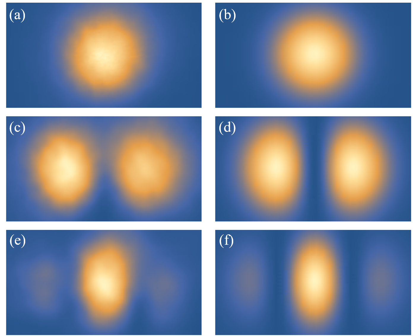
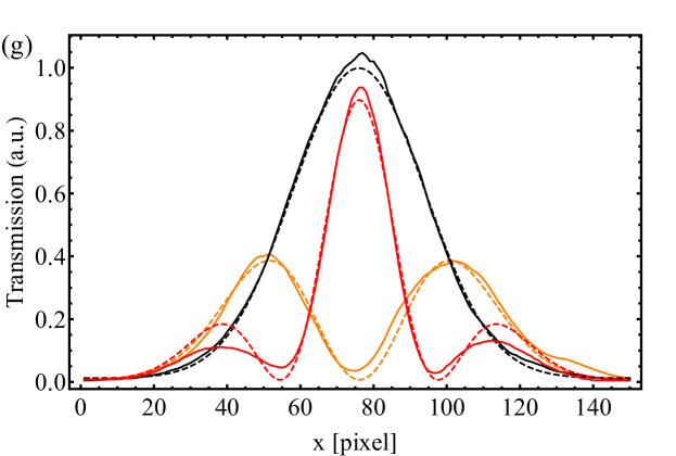
Second-order spatial differentiation is observed at normal incidence, while first-order spatial differentiation is observed at oblique incidence, with a rapid transition of the order of few tens of a degree. As examples, Figs. 7(c) and (e) show images of the transverse profile at the minimum transmission wavelength for and , respectively. Figures 7(d) and (f) show the results of fits to first-order differentiated () and second-order differentiated () Gaussian beam intensity profiles, respectively. The resulting fit coefficients are respectively 0.963 and 0.940, showing the good quality of the spatial differentiation. The transverse profiles of the central part of the different beams in the direction are shown in Fig. 7(g), together with the corresponding fit results.
Similar experiments were performed with the ”TE grating” previously described and similar results in excellent agreement with the theoretical predictions were obtained, as shown in the Appendix.
V Conclusion
In-depth investigations of spatial differentiation of optical beams by thin dielectric subwavelength gratings under various illumination (incidence angle, polarization) conditions were carried out. High quality first- and second-order spatial differentiation of a Gaussian beam was demonstrated at oblique and normal incidence, respectively. The experimental observations are in excellent agreement with the predictions of full RCWA simulations and the generic coupled-mode model of Bykov et al., which is used as a basis for calculating the transfer functions of the spatial differentiators. The direct patterning of suspended, essentially loss-free, commercial silicon nitride thin films using standard EBL and plasma techniques makess such compact spatial differentiators attractive for optical beam shaping, optical information processing and optomechanical sensing applications.
VI Appendix: ”TE grating”
Experiments similar to those described in Sec. IV were performed with the ”TE grating” previously described and similar results, which we show here for completeness, were obtained. The transmission spectra measured for different incidence angles are shown in Fig. 8; the first Fano resonance occurs at 958.3 nm at normal incidence, with a minimum transmission of 1.1%. At oblique incidence, the first Fano resonance is as expected shifted towards lower wavelengths, since the second Fano resonance occurs at a higher wavelength (outside the scanning range of the laser). First- and second-order spatial differentiation are also observed with similar behavior and quality as for the ”TM grating” (see Figs. 8 and 9).
Funding
Independent Research Fund Denmark.
References
- (1) A. Silva, F. Monticone, G. Castaldi, V. Galdi, A. Alu, and N. Engheta, ”Performing mathematical operations with metamaterials,” Science 343, 160 (2014).
- (2) A. Pors, M. G. Nielsen, and S. I. Bozhevolnyi, ”Analog computing using reflective plasmonic metasurfaces,” Nano Lett. 15, 79 (2015).
- (3) L. L. Doskolovich, D. A. Bykov, E. A. Bezus, and V. A. Soifer, ”Spatial differentiation of optical beams using phase-shifter Bragg grating,” Opt. Lett. 39, 1278 (2014).
- (4) N. V. Golovastikov, D. A. Bykov, and L. L. Doskolovich, ”Resonant diffraction gratings for spatial differentiation of optical beams,” Quantum Electron. 44, 984 (2014).
- (5) D. A. Bykov, L. L. Doskolovich, E. A. Bezus, and V. A. Soifer, ”Optical computation of the Laplace operator using phase-shifter Bragg gratings,” Opt. Express 22 25084 (2014).
- (6) Z. Ruan, ”Spatial mode control of surface plasmon polariton excitation with gain medium: from spatial differentiator to integrator,” Opt. Lett. 40, 601 (2015).
- (7) A. Youssefi, F. Zangeneh-Nejad, S. Abdollahramenazi, and A. Khavasi, ”Analog computing by Brewster effect,” Opt. Lett. 41, 3467 (2016).
- (8) Y. Hwang and T. J. Davis, ”Optical metasurfaces for subwavelength difference operations,” Appl. Phys. Lett. 109, 181101 (2016).
- (9) T. Zhu, Y. Zhou, Y. Lou, H. Ye, M. Qiu, Z. Ruan, and S. Fan, ”Plasmonic computing of spatial differentiation,” Nat. Commun. 815391 (2017).
- (10) F. Zangeneh-Nejad and A. Khavasi, ”Spatial integration by a dielectric slab and its planar graphene-based counterpart,” Opt. Lett. 42, 1954 (2017).
- (11) F. Zangeneh-Nejad, A. Khavasi, and B Rejaei, ”Analog optical computing by half-wavelength slabs,” Opt. Comm. 407, 338 (2018).
- (12) Y. Hwang, T. J. Davis, J. Lin, and X.-C. Yuan, ”Plasmonic circuit for second-order spatial differentiation at the subwavelength scale,” Opt. Express 26, 7368 (2018).
- (13) C. Guo, M. Xiao, M. Minkov, Y. Shi, and S. Fan, ”Photonic crystal slab Laplace operator for image differentiation,” Optica 5, 251 (2018).
- (14) D. A. Bykov, L. L. Doskolovich, A. A. Morozov, V. V. Podlipnov, E. A. Bezis, P. Verma, and V. A. Soifer, ”First-order optical spatial differentiator based on a guided-mode resonant grating,” Opt. Express 26, 10997 (2018).
- (15) Z. Dong, J. Si, X. Yu, and X. Deng, ”Optical spatial differentiator based on subwavelength high-contrast gratings,” Appl. Phys. Lett. 112, 181102 (2018).
- (16) B. Nair, A. Naesby, B. R. Jeppesen, and A. Dantan, ”Suspended silicon nitride thin films with enhanced and electrically tunable reflectivity,” Phys. Scr. 14, 125013 (2019).
- (17) A. Parthenopoulos et al., in preparation.
- (18) D. A. Bykov and L. L. Doskolovich, ”Spatiotemporal coupled-mode theory of guided-mode resonant gratings,” Opt. Express 23, 19234 (2015).
- (19) D. A. Bykov, L. L. Doskolovich, and V. A. Soifer, ”Coupled-mode theory and Fano resonances in guided-mode resonant gratings: the conical diffraction mounting,” Opt. Express 25, 1151 (2017).
- (20) C. J. Chang-Hasnain and W. Yang, ”High-contrast gratings for integrated optoelectronics,” Adv. Opt. Photon. 4, 379 (2012).
- (21) G. Quaranta, G. Basset, O. J. F. Martin, and B. Gallinet, ”Recent advances in resonant waveguide gratings,” Laser Photonics Rev. 12, 1800017 (2018).
- (22) J. D. Thompson, B. M. Zwickl, A. M. Jayich, F. Marquardt, S. M. Girvin, and J. G. E. Harris, ”Strong dispersive coupling of a high-finesse cavity to a micromechanical membrane,” Nature 452, 72-75 (2008).
- (23) U. Kemiktarak, M. Metcalfe, M. Durand, and J. Lawall, ”Mechanically compliant grating reflectors for optomechanics,” Appl. Phys. Lett. 100, 061124 (2012).
- (24) C. H. Bui, J. Zheng, S. W. Hoch, L. Y. T. Lee, J. G. E. Harris, and C. W. Wong, ”High-reflectivity, high-Q micromechanical membranes via guided resonances for enhanced optomechanical coupling,” Appl. Phys. Lett. 100, 021110 (2012).
- (25) U. Kemiktarak, M. Durand, M. Metcalfe, and J. Lawall, ”Cavity optomechanics with sub-wavelength grating mirrors,” New J. Phys. 14, 125010 (2012).
- (26) A. Xuereb, C. Genes, and A. Dantan, ”Strong Coupling and Long-Range Collective Interactions in Optomechanical Arrays,” Phys. Rev. Lett. 109, 223601 (2012).
- (27) R. A. Norte, J. P. Moura, and S. Gröblacher, ”Mechanical Resonators for Quantum Optomechanics Experiments at Room Temperature,” Phys. Rev. Lett. 116, 147202 (2016).
- (28) C. Reinhardt, T. Müller, A. Bourassa, and J. C. Sankey, ”Ultralow-Noise SiN Trampoline Resonators for Sensing and Optomechanics,” Phys. Rev. X 6, 021001 (2016).
- (29) J. Li, A. Xuereb, and D. Vitali, ”Cavity mode frequencies and strong optomechanical coupling in two-membrane cavity optomechanics,” J. Mod. Opt. 18, 084001 (2016).
- (30) X. Chen, C. Chardin, K. Makles, C. Caër, S. Chua, R. Braive, I. Robert-Philip, T. Briant, P.-F. Cohadon, A. Heidmann, T. Jacqmin, and S. Deleglise, ”High-finesse Fabry-Perot cavities with bidimensional Si3N4 photonic-crystal slabs,” Light Sci. Appl. 6, e16190 (2017).
- (31) B. Nair, A. Naesby, and A. Dantan, ”Optomechanical characterization of silicon nitride membrane arrays,” Opt. Lett. 42, 1341-1344 (2017).
- (32) J. P. Moura, R. A. Norte, J. Guo, C. Schäfermeier, and S. Gröblacher, ”Centimeter-scale suspended photonic crystal mirrors,” Opt. Express 26, 1895-1909 (2018).
- (33) A. Naesby and A. Dantan, ”Microcavities with suspended subwavelength structured mirrors,” Opt. Express 26, 29886 (2018).
- (34) C. Gärtner, J. P. Moura, W. Haaxman, R. A. Norte, and S. Gröblacher, ”Integrated optomechanical arrays of two high reflectivity SiN membranes,” Nano Lett. 18, 7171 (2018).
- (35) A. Cernotik, A. Dantan, and C. Genes, ”Cavity quantum electrodynamics with frequency-dependent reflectors,” Phys. Rev. Lett. 122, 243601 (2019).
- (36) A. Dantan, ”Membrane sandwich squeezed film pressure sensors,” arxiv:2004.11597 (2020).
- (37) S. K. Manjeshwar, K. Elkhouly, J. M. Fitzgerald, M. Ekman, Y. Zhang, F. Zhang, S. M. Wang, P. Tassin, and W. Wieczorek, ”Suspended photonic crystal membranes in AlGaAs heterostructures for integrated multi-element optomechanics,” Appl. Phys. Lett. 116, 264001 (2020).
- (38) T. Germer, Modeled Integrated Scatter Tool, available at http://physics.nist.gov/scatmech.
- (39) A. A. Darki, A. Parthenopoulos, J. V. Nygaard, and A. Dantan, ”Profilometry and stress analysis of suspended nanostructured thin films using Atomic Force Microscopy,” in preparation (2020).
- (40) S. Fan and J. D. Joannopoulos, ”Analysis of guided resonances in photonic crystal slabs,” Phys. Rev. B 65, 235112 (2002).
- (41) S. Fan, W. Suh, and J. D. Joannopoulos, ”Temporal coupled-mode theory for the Fano resonance in optical resonators,” J. Opt. Soc. Am. A 20, 569 (2003).