Generation of Coherent Phonons via a Cavity Enhanced Photonic Lambda Scheme
Abstract
We demonstrate the generation of coherent phonons in a quartz Bulk Acoustic Wave (BAW) resonator through the photoelastic properties of the crystal, via the coupling to a microwave cavity enhanced by a photonic lambda scheme. This is achieved by imbedding a single crystal BAW resonator between the post and the adjacent wall of a microwave reentrant cavity resonator. This 3D photonic lumped LC resonator at the same time acts as the electrodes of a BAW phonon resonator, and allows the direct readout of coherent phonons via the linear piezoelectric response of the quartz. A microwave pump, is tuned to the cavity resonance , while a probe frequency, , is detuned and varied around the red and blue detuned values with respect to the BAW phonon frequency, . The pump and probe power dependence of the generated phonons unequivocally determines the process to be electrostrictive, with the phonons produced at the difference frequency between pump and probe, with no back action effects involved. Thus, the phonons are created without threshold and can be considered analogous to a passive Coherent Population Trapped (CPT) maser scheme.
One of the major hurdles to engineer quantum systems for applications such as sensing and scalable quantum computing is decoherence – the computational advantages of entanglement are lost if one’s quantum state collapses too quickly. One main pathway of decoherence is the energy lost to the environment. Therefore, investigation into quantum hybrid systems that facilitate the transfer of energy from one form to another, an important protocol for quantum infrastructure, commonly look to utilise high quality factor resonators. As far as mechanical systems go, macroscopic single–crystal quartz bulk acoustic wave (BAW) resonators have demonstrated the largest products experimentally producible Goryachev et al. (2012, 2013); Galliou et al. (2013); Renninger et al. (2018); Kharel et al. (2019). These crystals are specifically engineered with a convex curvature that traps phonons in the centre of the resonator, drastically reducing contact losses at its peripheries. Given the piezoelectric nature of quartz, coupling to the acoustic modes is straight forward and can be achieved with an RF source and two electrodes placed on either side of the crystal. Typically these electrodes are placed as close as possible to the crystal to achieve high electromechanical coupling, without touching, to preserve high mechanical -factors. Given their macroscopic size (weighing on the order of grams) and their excellent frequency stability, these devices have been proposed for use in tests of fundamental physics such as Lorentz invariance Goryachev et al. (2018); Lo et al. (2016), quantum gravity Bushev et al. (2019), high frequency gravity wave detectors Goryachev and Tobar (2014) and the search for scalar dark matter Arvanitaki et al. (2016).
Only recently has optomechanical coupling to GHz mechanical modes in such crystals been achieved using two counter-propagating lasers Renninger et al. (2018); Kharel et al. (2019). The aforementioned work represents a new form of optomechanical system, and successfully interacts with the quartz mechanical modes without the use of piezoelectricity. Whilst piezoelectricity allows strong electromechanical coupling between photons and acoustic phonons, it is extremely valuable to explore coupling between different frequency ranges of these two interacting energy forms in order to improve the versatility and bandwidth of the quartz BAW as a potential quantum hybrid system. Here, we demonstrate coupling between a microwave resonant cavity and high quality factor quartz BAW resonant modes at MHz frequencies. This demonstration was achieved in two ways, firstly through the generation of mechanical sidebands on the microwave carrier when both phonon and photon modes are driven simultaneously, and secondly by exciting the acoustic mode (monitored via piezoelectricity) using two microwave tones, offset by the mechanical frequency. The latter is inherently a nonlinear effect given two GHz frequency tones produce a MHz frequency acoustic excitation, hence excitation via photoelasticity over piezoelectricity, with the later a linear phenomenon.
Phonon masers (or lasers) have been recently realised and have a clear threshold in generation of phonons in analogy to a photonic maser with population inversion Vahala et al. (2009); Grudinin et al. (2010); Mahboob et al. (2013); Navarro-Urrios et al. (2015). In contrast a Coherent Population Trapped (CPT) maser operates in a lambda scheme, where two photon tones excite an atomic transition without population inversion through a non-linear process Godone et al. (2000); Vanier (2005); Godone et al. (2004). Our system is similar to the CPT maser and has no input power threshold for the generation of phonons, allowing transduction of small microwave signals into mechanical frequencies, potentially at the level of a single phonon. We also note that similar techniques have been used to generate coherent phonons, but from optical frequencies Lanzillotti-Kimura et al. (2011, 2007); Kharel et al. (2019).
The quartz BAW under study in this experiment was very similar to those used in Goryachev et al. (2012): a state of the art SC-cut (Stress Compensated) EerNisse (1975) quartz single crystal utilising BVA technology Besson (1977). The resonator was ultrasonically machined into a planoconvex shape Stevens and Tiersten (1986a); bulging on one side in its centre. A periphery supporting ring was also machined out of the single quartz crystal, which provides a location to hold the crystal in place. The BAW had a diameter of mm, central thickness of mm, and radius of curvature of the convex side of mm. Three types of acoustic modes exist; longitudinal modes, fast shear modes, and slow shear modes, or A, B and C-modes, respectively; a result of the anisotropy of quartz. BVA resonators are constructed with “non-contacting” electrodes placed on either side of the crystal, allowing efficient electromechanical coupling through the quartz’s piezoelectricity. These electrodes will only detect a voltage difference across the crystal for an odd harmonic of the A, B or C modes; requiring opposite signed signals at either end of the crystal. Similarly, only odd harmonics can be excited by applying an RF voltage difference to the electrodes. The harmonic of the A, B and C modes for the given crystal at 4 K are located at 9.415 143 MHz, 5.500 049 MHz, and 4.996 171 MHz, respectively. The quality factors of these modes improve under vacuum and cryogenic conditions, capable of approaching Galliou et al. (2013).
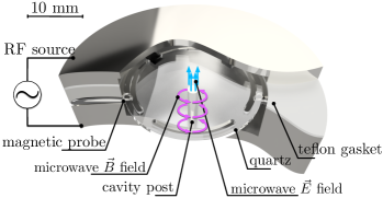
The conducting surfaces of the electrodes potentially interfere with any microwave modes in a cavity QED-like experiment, so the mechanical resonator investigated here does not have any electrodes included. Instead, the top half and bottom half of the microwave cavity were insulated from each other by a teflon layer, allowing electromechanical coupling to the quartz crystal across the two halves of the cavity, hence the cavity can also be utilised as a set of electrodes (see Fig.1).
The microwave cavity takes the form of a re-entrant, or Klystron cavity Floch et al. (2013): an empty cylindrical space with a conducting post in the centre, which extends from one end-face towards the other, stopping short so as to form a gap between the top of the post and the lid of the cavity. The resonant microwave frequency re-entrant mode is characterised by majority of electric field confined in this gap and the magnetic field circling around the post as shown in Fig.1, and thus the metallic rod forms a 3D lumped element LC resonator. The re-entrant cavity had a resonant frequency of GHz. Microwaves were coupled into and out of the re-entrant cavity via co-axial cables, which were terminated by loops inside the cavity, hence producing an oscillating electromagnetic field. One of the main loss mechanisms at cryogenic temperatures is the surface resistance of the cavity walls. To minimise this, the cavity is constructed from pure Niobium, which becomes superconducting at K. However, the teflon gasket separating the two halves of the cavity resulted in some losses via leakage, limiting the microwave resonance’s -factor to about at 4 K.
The quartz BAW resonator is placed within the gap between the re-entrant cavity’s post and lid – such that its centre overlaps with the location of highest microwave electric field concentration. This is because the centre of the crystal is the location of its mechanical modes, and a high degree of overlap between the mechanical and microwave modes will result in a larger photoelastic coupling. Recently a similar type of 3D cavity structure was used for transduction from microwave to optical frequenciesRamp et al. (2020). The crystal was supported via three rigid blocks attached to the inside wall of the cavity upon which the peripheral support ring of the BAW makes contact. Due to the photoelastic effect, mechanical strain of the quartz results in a periodic modulation of the dielectric permittivity over the crystal volume. This modulation changes the nature of the media through which the resonant re-entrant mode’s electric field is oscillating. This results in a frequency shift of the microwave mode and hence a form of optomechanical coupling. Via the inverse process, electrostriction (or photoelastic response), an applied electric field induces strain within the crystal due to a slight displacement of ions.
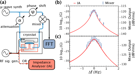
The optomechanical coupling was determined by exciting the quartz mechanical modes piezoelectrically, and measuring the effect on the resonant microwave mode using a “phase-bridge” setup. To do this, a setup like that in figure 2 (a) was used. A microwave synthesiser continuously pumps the re-entrant cavity mode at 4.095 GHz, whilst an RF signal generator applies a MHz signal across the cavity lid and base. The transmitted microwave signal is then mixed down against the input signal from the synthesiser, which is phase shifted such that the mixer will output a voltage proportional to any phase shift produced in the resonator, which is manifested as a frequency shift in the resonator’s arm of the bridge. By observing the output spectra of the mixer on an Agilent 89410A Vector Signal Analyser (FFT), one can measure the strength of modulation on the resonant microwave mode caused by the mechanical motion of the quartz. By applying a continuous wave RF voltage across the microwave cavity this can be done in the static regime - measuring the mixer output at and around mechanical resonant frequencies. The results of this experiment, sweeping the signal generator over the 4.996 MHz and 9.415 MHz modes are shown in Fig. 2(b) and (c), respectively by the blue points. These measurements were taken with synthesiser power at 15 dBm, attenuation to the cavity dBm, and a 10 mV amplitude signal applied by the RF signal generator around the mechanical resonance frequency. The conversion efficiency of the phase-bridge setup (the voltage output by the mixer given some frequency shift in the resonator arm) is measured using an artificial modulation signal to be V/kHz.
The acoustic resonances of the quartz were also directly measured by an impedance analyser connected across the microwave cavity. From the measurements of impedance and phase, one can determine the conductance, across the “electrodes”, which is plotted in red for the 4.996 MHz and 9.415 MHz modes in Fig.2(b) and (c), respectively. We see that the static measurements of the phase bridge mixer output match the measurements of within experimental error, given some coefficient of mixer conversion efficiency. This demonstrates that the modulation of the microwave resonant mode measured by the phase bridge was a result of the mechanical excitation. These measurements also allow an accurate way to determine factors; for the 4.996 MHz mode and for the 9.415 MHz mode, and the , and values for the equivalent electrical circuit of the mechanical resonance. These measurements also allowed the determination of the displacement of the quartz crystal when the aforementioned 10 mV signal was applied, and hence the single-photon optomechanical coupling rate, . The value represents the frequency shift of the electromagnetic mode caused by the displacement of the mechanical system when a single photon enters the electromagnetic system.
The charge and displacement in a piezoelectrical system are related in a linear fashion by an electromechanical coupling constant Goryachev and Tobar (2014):
| (1) |
where
| (2) |
Here, is the effective mass of the resonance, the resonant frequency, and its effective resistance. For MHz, an rms charge is determined from the applied mV and the equivalent resistance . kg is determined from finite element modelling Carvalho et al. (2019). This nets an rms displacement of nm. The simple relationship
| (3) |
will allow us to relate the calculated displacement to the output voltage of the mixer from the aforementioned frequency sensitivity of the phase bridge and the dependence of the electromagnetic frequency on displacement , where is the so-called zero-point fluctuation of the mechanical resonance. Substituting in all relevant numerical values nets a single-photon optomechanical coupling rate of nHz, which is in excellent agreement with simulated results of the photoeleastic coupling rate in this system Carvalho et al. (2019).
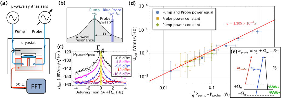
The second technique used to excite the mechanical modes involved two microwave tones in a Brillouin-like setup Renninger et al. (2018). The two signals were input to the microwave cavity via loop probes, and the spectra of the potential difference across the cavity was measured on a FFT spectrum analyser as shown in figure 3(a). The output voltage measured in this way was therefore directly proportional to the displacement of the piezoelectric quartz.
The FFT window was centred at the acoustic resonant frequency with a 10 Hz span; aiming to detect the voltage spectra produced by the mechanical motion of the piezoelectric quartz. One microwave signal; the pump, was tuned on resonance , whilst the other; the probe, was detuned by some amount. The probe microwave source was swept from Hz to Hz in the red detuned case, and Hz to Hz in the blue detuned case. This scheme is demonstrated in figure 3(b) for the blue-detuned case. Results of the red-detuned case are identical.
The output voltage produced by the quartz crystal is plotted in fig 3(c) as the probe synthesiser is detuned from . Mechanical motion of the quartz is generated through nonlinear mixing the two microwave input signals, a result of electrostriction. Electrostriction (or photoelasticity) is a quadratic phenomenon that relates strain to the square of electric polarisation according to:
| (4) |
where is the second-order strain tensor, the four rank electrostriction coefficient, the electrical susceptibility (can be simplified to a scalar) and , electric fields. The quadratic nature of the electrostriction generates a double frequency and difference frequency term. When the difference frequency is equal to a mechanical resonant frequency of the quartz crystal, it will be resonantly enhanced. Given the piezoelectric nature of the quartz, this will generate an electric field at the same difference frequency, and hence a voltage across the “electrodes”; i.e. the top and the bottom of the cavity.
The strain produced by electrostriction acts as a driving term in the piezolectric equations of motion Stevens and Tiersten (1986). A full theoretical derivation of this process is given in the supplementary materials, which demonstrates that the voltage across the top and bottom of the cavity is . The dependence of on the pump and probe powers is plotted in figure 3(d), demonstrating this proportionality. The nonlinear process described here necessitates that the coherence of the pump and probe signals is maintained by the generated phonons.
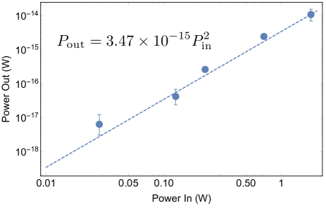
From the above relationship, we can expect a quadratic dependence of output power on input power as demonstrated by figure 4. Output power is derived from the measurements in figure 3(c). The efficiency is very low given the small value of ; a result of lower optical and mechanical frequencies relative to previous publications Lanzillotti-Kimura et al. (2011, 2007); Kharel et al. (2019), and suboptimal electromechanical coupling to the quartz piezoelectric current, resulting in some of the signal being lost at the readout stage.
Nevertheless, the lack of apparent threshold for the generation of phonons means that the smallest possible detected signal was determined by the noise floors, which include the instrument readout, the noise temperature of amplification.
Given the microwave mode is a lumped resonator, the typical phase matching conditions of a Brillouin scheme are lifted. Instead, all that is necessary for the generation of mechanical phonons is conservation of energy between the two microwave fields and the acoustic mode, with the generated phonons directly detected through the direct electrical readout of the piezoelectric quartz. This scheme is analogous to a passive CPT maser Godone et al. (2000); Vanier (2005); Godone et al. (2004), in which two detuned optical pumps generate a microwave signal near the frequency of a hyperfine splitting, but determined by the frequency difference of the optical pumps due to the non-linearity. Exactly like CPT maser, the observed excitation demonstrates no threshold, as shown by Fig.3(d). The allowable frequency range of the excited coherent phonons (Fig.3(c)) increases as a function of applied power, demonstrated in Fig.5.
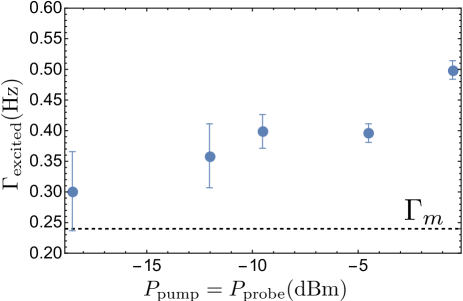
In conclusion we have demonstrated a way to calibrate an optomechanical system coupled through a non-linear electrostrictive coupling. By implementing a two-photon lambda excitation coherent phonons were generated, with a bandwidth of generation greater than the acoustic linewidth. This technique is analogous to a CPT maser, and gives a way to generate coherent phonons with no power threshold.
The data that support the findings of this study are available from the corresponding author upon reasonable request.
Supplementary Material
Please find a complete theoretical derivation of the photoelastic coupling mechanism described above in the Supplementary Material. Here, it is shown how the dependence of the output voltage measured of the quartz resonator in the two tone experiment is proportional to the square root of the product of the two incident powers of the microwave signals.
This work was supported by Australian Research Council grant number CE170100009 and a UWA Research Collaboration Award with IMT-Atlantique.
References
- Goryachev et al. (2012) M. Goryachev, D. L. Creedon, E. N. Ivanov, S. Galliou, R. Bourquin, and M. E. Tobar, Applied Physics Letters 100, 243504 (2012), https://doi.org/10.1063/1.4729292 .
- Goryachev et al. (2013) M. Goryachev, D. L. Creedon, S. Galliou, and M. E. Tobar, Phys. Rev. Lett. 111, 085502 (2013).
- Galliou et al. (2013) S. Galliou, M. Goryachev, R. Bourquin, P. Abbé, J. P. Aubry, and M. E. Tobar, Scientific Reports 3, 2132 (2013).
- Renninger et al. (2018) W. H. Renninger, P. Kharel, R. O. Behunin, and P. T. Rakich, Nature Physics (2018), 10.1038/s41567-018-0090-3.
- Kharel et al. (2019) P. Kharel, G. I. Harris, E. A. Kittlaus, W. H. Renninger, N. T. Otterstrom, J. G. E. Harris, and P. T. Rakich, Science Advances 5 (2019), 10.1126/sciadv.aav0582.
- Goryachev et al. (2018) M. Goryachev, Z. Kuang, E. N. Ivanov, P. Haslinger, H. Müller, and M. E. Tobar, IEEE Transactions on Ultrasonics, Ferroelectrics, and Frequency Control 65, 991 (2018).
- Lo et al. (2016) A. Lo, P. Haslinger, E. Mizrachi, L. Anderegg, H. Müller, M. Hohensee, M. Goryachev, and M. E. Tobar, Physical Review X 6, 011018 (2016).
- Bushev et al. (2019) P. A. Bushev, J. Bourhill, M. Goryachev, N. Kukharchyk, E. Ivanov, S. Galliou, M. E. Tobar, and S. Danilishin, Phys. Rev. D 100, 066020 (2019).
- Goryachev and Tobar (2014) M. Goryachev and M. E. Tobar, Phys. Rev. D 90, 102005 (2014).
- Arvanitaki et al. (2016) A. Arvanitaki, S. Dimopoulos, and K. V. Tilburg, Physical Review Letters 116 (2016).
- Vahala et al. (2009) K. Vahala, M. Herrmann, S. Knünz, V. Batteiger, G. Saathoff, T. W. Hänsch, and T. Udem, Nature Physics 5, 682 (2009).
- Grudinin et al. (2010) I. S. Grudinin, H. Lee, O. Painter, and K. J. Vahala, Phys. Rev. Lett. 104, 083901 (2010).
- Mahboob et al. (2013) I. Mahboob, K. Nishiguchi, A. Fujiwara, and H. Yamaguchi, Phys. Rev. Lett. 110, 127202 (2013).
- Navarro-Urrios et al. (2015) D. Navarro-Urrios, N. E. Capuj, J. Gomis-Bresco, F. Alzina, A. Pitanti, A. Griol, A. Martínez, and C. M. Sotomayor Torres, Scientific Reports 5, 15733 (2015).
- Godone et al. (2000) A. Godone, F. Levi, S. Micalizio, and J. Vanier, Phys. Rev. A 62, 053402 (2000).
- Vanier (2005) J. Vanier, Applied Physics B 81, 421 (2005).
- Godone et al. (2004) A. Godone, F. Levi, S. Micalizio, and C. Calosso, Phys. Rev. A 70, 012508 (2004).
- Lanzillotti-Kimura et al. (2011) N. D. Lanzillotti-Kimura, A. Fainstein, B. Perrin, B. Jusserand, L. Largeau, O. Mauguin, and A. Lemaitre, Phys. Rev. B 83, 201103 (2011).
- Lanzillotti-Kimura et al. (2007) N. D. Lanzillotti-Kimura, A. Fainstein, A. Huynh, B. Perrin, B. Jusserand, A. Miard, and A. Lemaître, Phys. Rev. Lett. 99, 217405 (2007).
- EerNisse (1975) E. EerNisse, in 29th Annual Symposium on Frequency Control (Electronic Industries Association, 1975) pp. 1–4.
- Besson (1977) R. Besson, in 31st Annual Symposium on Frequency Control (Electronic Industries Association, 1977) pp. 147–152.
- Stevens and Tiersten (1986a) D. Stevens and H. Tiersten, J. Acous. Soc. Am. 79 (1986a).
- Floch et al. (2013) J.-M. L. Floch, Y. Fan, M. Aubourg, D. Cros, N. C. Carvalho, Q. Shan, J. Bourhill, E. N. Ivanov, G. Humbert, V. Madrangeas, and M. E. Tobar, Review of Scientific Instruments 84, 125114 (2013), https://doi.org/10.1063/1.4848935 .
- Ramp et al. (2020) H. Ramp, T. J. Clark, B. D. Hauer, C. Doolin, K. C. Balram, K. Srinivasan, and J. P. Davis, Applied Physics Letters 116, 174005 (2020), https://doi.org/10.1063/5.0002160 .
- Carvalho et al. (2019) N. C. Carvalho, J. Bourhill, M. Goryachev, S. Galliou, and M. E. Tobar, Applied Physics Letters 115, 211102 (2019), https://doi.org/10.1063/1.5127997 .
- Stevens and Tiersten (1986b) D. S. Stevens and H. F. Tiersten, The Journal of the Acoustical Society of America 79, 1811 (1986b), https://doi.org/10.1121/1.393190 .
Supplementary Material: Output voltage from two applied microwave sources
We drive the microwave cavity with two tones, at frequency and at frequency , where is the microwave resonant frequency of the cavity. Given the re-entrant cavity architecture, the electric field exists between the top of the post and the roof of the cavity and can therefore be approximated as the electric field inside a capacitor; i.e. in the cavity’s -direction and uniform throughout. Therefore we can write the electric fields between the top of the post and the roof of the cavity as:
| (S5) |
where is the electric field amplitude and and represent the phase of both signals.
The two electric fields across the quartz crystal will interact via electrostriction; a quadratic phenomenon that relates strain to the square of electric polarisation P, according to:
| (S6) |
where is the second-order strain tensor, the four rank electrostriction tensor coefficient, the electrical susceptibility and , electric fields. Substituting and into S6 gives:
| (S7) |
Given the two applied -fields are forced into the -direction ( in figure S1) by the cavity, it follows that strain components will be determined by the electrostriction tensor components (modified in this case to ). If (i.e. ), the frequency of a resonant mechanical BAW mode in the quartz crystal, the low frequency component in equation S7 will generate strain at the frequency which will be resonantly enhanced, and hence we can ignore the higher frequency term, which will not be seen by the mechanical system. This strain term will appear as an additional term in the standard piezoelectric differential equation of motion Stevens and Tiersten (1986):
| (S8) |
where , , and are the components of stress, mechanical displacement, and electric displacement, respectively; and are the mass density and electric potential, respectively; and , and are the elastic, piezoelectric, and dielectric constants, respectively.
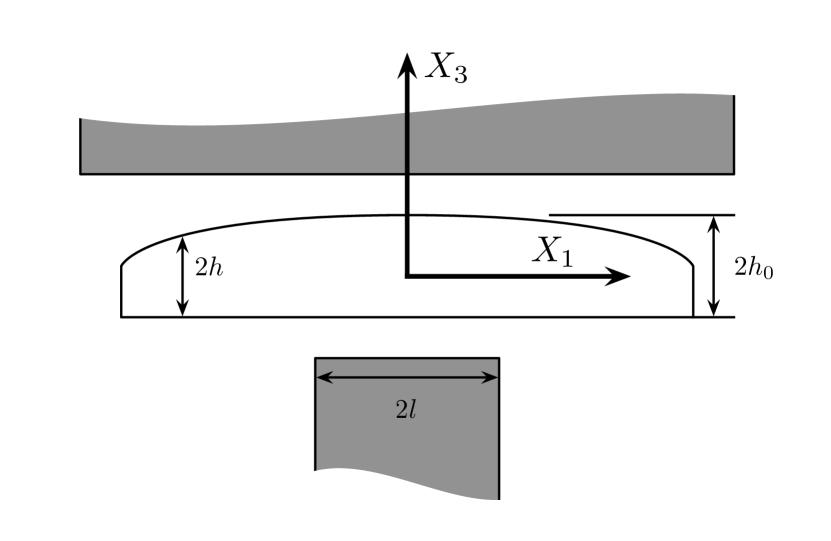
Given we deal with a plano-convex crystal architecture (see fig. S1) and are interested in only the third overtone of the pure shear mode (with resonant frequency ) the equation of motion for displacement becomes Stevens and Tiersten (1986) (setting the tunable ):
| (S9) |
where is the component of mechanical displacement in the direction; , and are constants formulated from various elastic tensor and dimensional values Stevens and Tiersten (1986); and are the height of the crystal at its centre and its radius of curvature, respectively; and , where , where is the speed of the acoustic wave in the direction.
Equation S9 will have solutions of the form:
| (S10) |
and, as usual, is replaced by
| (S11) |
in which is the unloaded quality factor of the resonant mode. From equation S8, and assuming some scalar potential exists from the resulting electric field where quantities are varying at , and various simplifications Stevens and Tiersten (1986) we can state that
| (S12) |
from which the current generated by the crystal’s motion can be obtained by integrating over the crystal area:
| (S13) |
where is the area of the “electrodes”, and we are able to remove all terms independent of and from the integration, which assumes the electric fields are constant over the area of the crystal.
The current generated by the crystal between the electrodes is received at the 50 terminal of the FFT device as a voltage . We can see from the from of equation S13 that the amplitude of this voltage will be proportional to and hence when i.e. the detuning .
Given we are assuming these fields are approximately those of a parallel plate capacitor we can relate the amplitude of the fields to the input power of the driving signals by considering the entire microwave cavity system as a lumped parallel LCR circuit and therefore the voltage drop across the capacitor to its reactance, and the input powers, :
| (S14) |
where is the distance between the top of the post and the roof.
Therefore, we can state that the voltage read from the FFT will have the proportionality:
| (S15) |
References
- Stevens and Tiersten (1986) D. S. Stevens and H. F. Tiersten, The Journal of the Acoustical Society of America 79, 1811 (1986), https://doi.org/10.1121/1.393190 .