Single-Photon Stored-Light Interferometry
Abstract
We demonstrate a single-photon stored-light interferometer, where a photon is stored in a laser-cooled atomic ensemble in the form of a Rydberg polariton with a spatial extent of . The photon is subject to a Ramsey sequence, i.e. ‘split’ into a superposition of two paths. After a delay of up to 450 ns, the two paths are recombined to give an output dependent on their relative phase. The superposition time of 450 ns is equivalent to a free-space propagation distance of 135 m. We show that the interferometer fringes are sensitive to external fields, and suggest that stored-light interferometry could be useful for localized sensing applications.
I Introduction
Interferometers Adams and Hughes (2018) are a versatile tool in engineering, oceanography, seismology, metrology and astronomy Abbott et al. (2016). Replacing photons by massive particles creates an interferometer Adams et al. (1994) that is sensitive to gravity and other inertial effects. Interferometry using the internal quantum states of atoms Ramsey (1950, 1990) has become an important technique in the measurement of time and quantum coherence. Hybrid light-matter interferometers are also possible. In a slow-light interferometer Shi et al. (2007), the field is partly photonic and partly atomic. A hybrid atom-light interferometer using internal atomic states to form a beam splitter has also been demonstrated Chen et al. (2015). Interferometry using atomic Rydberg states is useful in the detection of electric fields, as demonstrated using individual atoms Facon et al. (2016), atomic beams Palmer and Hogan (2019) and Rydberg-dressed cold-atom ensembles Arias et al. (2019). For all types of interferometry, the measurement sensitivity is limited by the time between the splitting and recombination processes, which is typically proportional to the length of the interferometer arms.
Here, we propose and demonstrate a hybrid interferometer based on a single photon stored as a spin wave in a cold atomic gas. The advantage of using stored light (or slow light) is that superposition time is decoupled from the size of the interferometer. For example, we demonstrate a quantum superposition time of 450 ns—equivalent to a free-space interferometer path length of 135 metres—using an inferterometer localized to a few microns. The two paths of the interferometer are formed by driving the spin wave into a superposition of quantum states. We employ highly-excited Rydberg states which allows the splitting and recombining of the optical paths to be performed using a microwave field. Similar to other Rydberg experiments Facon et al. (2016); Palmer and Hogan (2019); Arias et al. (2019), the output is sensitive to DC and AC electric fields. As the interferometer is localized over a length scale of only a few microns, the Rydberg blockade mechanism Lukin et al. (2001) forces the interferometer to operate with only one photon at a time. This has the advantage that phase shifts due to atom-atom interactions are suppressed. Both localisation and the single-photon character may be advantageous in some measurement applications, such as sensing and imaging Sedlacek et al. (2012); Fan et al. (2015); Facon et al. (2016); Wade et al. (2017).
II Experimental Demonstration
The principle of our single-photon stored-light interferometer is illustrated in Fig. 1. To store a photon, first laser-cooled atoms are loaded into an 862 nm optical dipole trap with a waist and a trap depth of . The atoms are optically pumped into the sublevel. Next, we illuminate the laser-cooled atomic ensemble with both a probe laser (780 nm) and a control laser (480 nm) for 500 ns. The probe beam, resonant with transition is focused into the ensemble with a beam waist of . The control beam, resonant with the transition is focused to a waist of . The probe and control beams are circularly polarized and counter-propagate. Before the probe is switched off, the control is ramped down to zero Möhl et al. (2020). The spatial extent of the stored photon is of order .
After storage, the stored photon is ‘split’ using a microwave field that couples the highly-excited Rydberg state, , to another Rydberg state , shown in yellow in Fig. 1(a). The microwave field amplitude is uniform over the dimensions of the stored photon. The microwave pulse, lasting 25 ns, is calibrated as a /2 pulse to realise the superposition state . After a period of free evolution, , the microwave source drives another /2 pulse to recombine the two paths. Finally, the population in is measured by coupling this state back to using the control field (shown in blue in Fig. 1). Each experimental run is performed thousands of times. A complete run consists of laser cooling and trapping for 120 ms followed by 20,000 individual interferometer measurements performed on the same ensemble in 90 ms. This gives an effective repetition rate of 95 kHz. All the cooling and trapping lasers are turned off during the interferometer measurements. The transmission of probe beam is measured throughout using a single-photon counter, see Fig. 1(b). More details on experimental apparatus and the relevant atomic levels can be found in previous work Busche et al. (2016, 2017); Möhl et al. (2020).
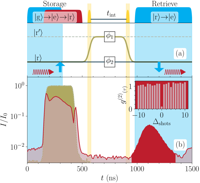
We employ highly-excited Rydberg states with principle quantum numbers in the range . The Rydberg blockade mechanism Lukin et al. (2001); Li and Kuzmich (2016); Ornelas-Huerta et al. (2020) limits the inteferometer to only one photon at a time. To demonstrate this we perform a Hanbury Brown Twiss (HBT) measurement on the light retrieved from the ensemble. The retrieved light is split by a 50:50 beam splitter and sent to two detectors. The normalised coincidence counts for a single retrieval is strongly suppressed, see Fig. 1b(inset). For a Rydberg state with principal quantum number , the probability to observe two photons in the same experimental shot, characterised by the normalized second-order intensity correlation, is . The correlation function between successive shots is unity as expected.
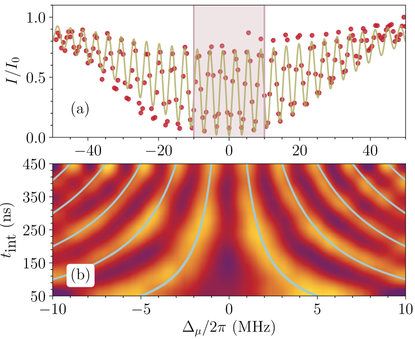
The output of the interferometer has the form Adams and Hughes (2018)
| (1) |
where and is the detuning of the microwave field. Consequently, to measure the interference fringes we can either vary the microwave field frequency, , or the superposition time, . Note the phase and hence the intensity output are also sensitive to any perturbation in the energy levels, and . The interference fringes as a function of both the microwave field detuning, , and the superposition time, , are shown in Fig. 2. In Fig. 2(a) we show the fringes for ns. In the experiment, the visibility of the interference fringes is reduced by technical factors including the imperfect removal of population from the Rydberg manifold after each shot of the experiment, and imperfect polarization of the microwave fields. Future work will focus on improving addressing these technical issues. In Fig. 2(b) we focus on the interference fringes in the range to 10 MHz, and show the effect of varying the superposition time, . The data are overlaid with theoretical retrieval maxima in yellow. As expected, as we increase , the interferometer becomes more sensitive to changes in the relative phase. In the current experiment, is limited to of order 1000 ns by motional dephasing Busche et al. (2017), which scrambles the information about the stored photon.
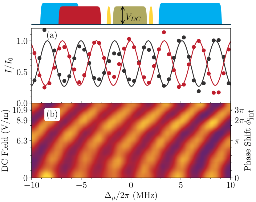
Next, we demonstrate the sensitivity of the interferometer fringes to external fields. First, we apply a DC electric field. This has the effect of shifting the energy levels due to the DC Stark effect, i.e.
| (2) |
where is the polarizability of the state , and is the applied electric field. The external field is applied during the superposition time between the two microwave -pulses, see Fig. 3(top). Fig. 3(a) shows the interference fringes at zero field and a DC field of 6.3 V/m. At this field value the phase shift is . Note that the fringe contrast is conserved, as the DC field only induces a global phase shift, without perturbing the spatial mode of the photon. Figure 3(b) shows the fringe shift from 0 to 12 V/m, with the phase shift indicated on the right-hand axis. As expected we observe a quadratic shift of the Ramsey fringes matching the relative dc-Stark shift of states and .
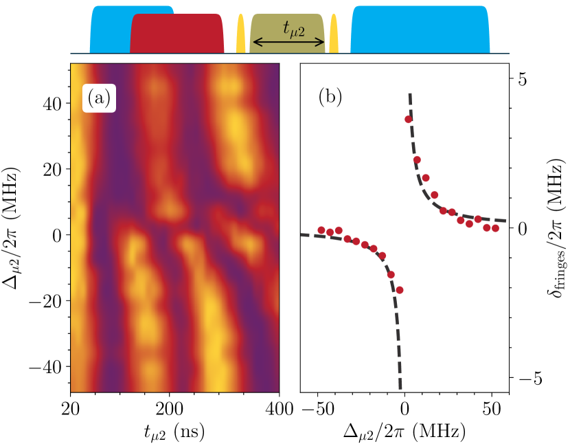
Second, we investigate the sensitivity of our single-photon stored-light interferometer to an external AC electric field. In the case of AC fields, the polarizabilities, and , exhibit resonances at particular rf, microwave and terahertz frequencies that match electric dipole allowed transitions between atomic Rydberg states, and these resonances have emerged as a promising platform for sensitive measurements of rf Jing et al. (2020) and terahertz Downes et al. (2020) fields. The sensitivity of the interferometer to a near-resonant external microwave field is predicted by the AC stark shift of individual Rydberg states. The energy shift of a state can be represented by
| (3) |
where is the electric dipole moment for a transition between states and , is the frequency of the external field, and is the resonant transition frequency between and . In the experiment, we use an interferometer based on the states and . The external microwave field is chosen to couple to another Rydberg state . The resonant frequency for this case is 18.2 GHz and the transition has a dipole moment, Debye Šibalić et al. (2017). The pulse sequence is shown in Fig. 4(top). The additional microwave field (green) is applied during the interferometer superposition time between the two -pulses (yellow). Figure 4a shows measurements of the single-photon Ramsey fringes as a function of both the detuning of the additional microwave field, , and the superposition time, . Fig. 4(b) shows how the shift of the interference fringes follows a dispersive-like law as expected. A fit to equation equation 3—the dotted line in the figure—is in good agreement with the data.
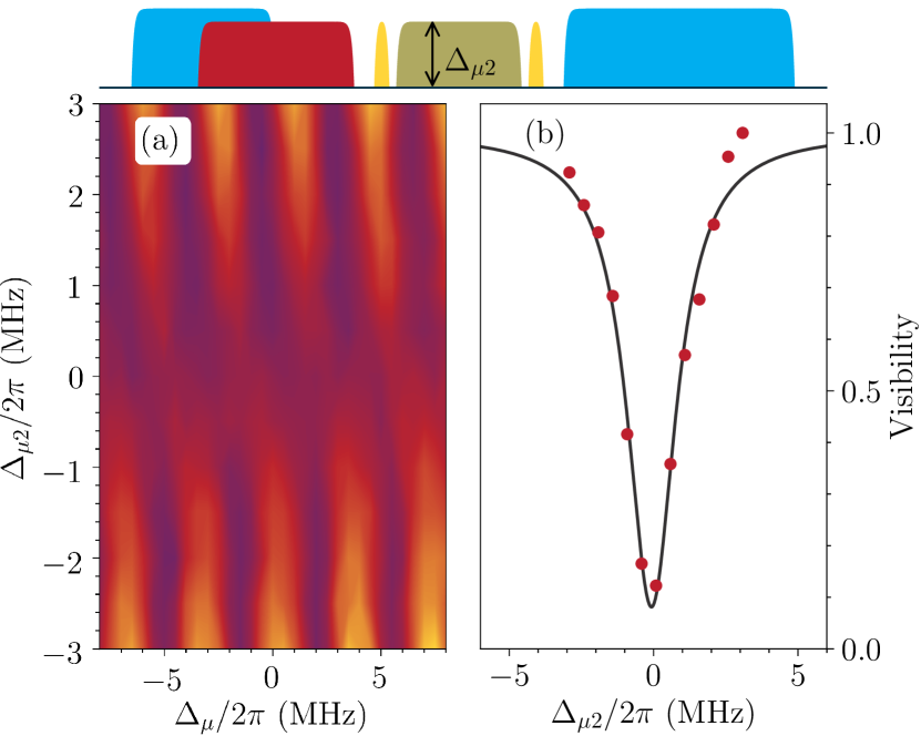
An interesting feature of the stored-light interferometer is that it provides two ways of measuring an external rf field, first via a fringe shift as shown in Fig. 4, and second via the loss of visibility. Figure 5 shows rf sensing data in the vicinity of a resonance. Figure 5(a) show the Ramsey fringes as function of the detuning of the microwave field, , while varying detuning of the external rf field, . In contrast, to the DC field case, Fig. 3, now we observe a change in the fringes visibility in the vicinity of the microwave resonance. When the external field is close to a resonance with another Rydberg state, we see a dramatic loss of fringes contrast. This is plotted in Fig. 5b. The loss occurs because there is a probability that a part of the photon energy is coupled into microwave field similar to the classic decoherence experiment of Brune et al. Brune et al. (1996). The data is fitted with a lineshape that is consistent with Fourier transform of the microwave pulse duration of 200 ns. Compared to Fig. 4, this plot illustrates how the loss of coherence is more frequency selective than the phase shift, and could be used for high-resolution measurements of Rydberg transition frequencies, which are important in the determination of quantum defects Li et al. (2003).
Applications of the single-photon interferometer will be explored in further work. For sensing applications, the current experiment is limited by shot noise (in contrast to classical measurements Arias et al. (2019), quantum measurement is limited to only one photon per shot) and photon storage time. The latter could be greatly increased by eliminating motional dephasing of the spin wave, either by using Doppler-free configuration Šibalić et al. (2016), or using an optical lattice to localise the atoms Schnorrberger et al. (2009). Ultimately, the fundamental limit is the lifetime of the Rydberg states which for circular states can be s Nguyen et al. (2018). Using these techniques, a stored-light interferometer could rival state-of-the-art electrometers Facon et al. (2016); Arias et al. (2019); Jing et al. (2020).
III Conclusion
In summary, we have realized a single-photon stored-light Ramsey-type interferometer via storing optical photons as Rydberg polaritons. The character of the Ramsey-like interference fringes has been demonstrated. We show that the interferometer, localized to a length scale of just a few microns, can be used to measure external fields. In these examples, information about the field is mapped onto the quantum state of the stored photon. This can lead to both changes in the fringe position and visibility. Our method paves the way towards advanced quantum probing of external fields. Potential applications include precision measurement of Rydberg transition frequencies, and sensing any field that perturbs either of the Rydberg states involved. The interferometer can be made sensitive to single optical photons by mapping them into Rydberg polaritons Paredes-Barato and Adams (2014), and could be used as the basis to realise a photonic phase gate Tiarks et al. (2019).
Funding and Acknowledgements. We acknowledge support from Engineering and Physical Sciences Research Council (EPSRC) Grants EP/M014398/1, EP/R002061/1 and EP/S015973/1. The figure data are available on the Durham University Collections repository (doi:10.15128/r2r207tp335).
References
- Adams and Hughes (2018) C. S. Adams and I. G. Hughes, Optics f2f: From Fourier to Fresnel (Oxford University Press, 2018).
- Abbott et al. (2016) B. P. Abbott, R. Abbott, T. D. Abbott, M. R. Abernathy, F. Acernese, K. Ackley, C. Adams, T. Adams, P. Addesso, and R. X. Adhikari, Phys. Rev. Lett. 116, 1 (2016), arXiv:1602.03837 .
- Adams et al. (1994) C. S. Adams, M. Sigel, and J. Mlynek, Physics Reports 240, 143 (1994).
- Ramsey (1950) N. F. Ramsey, Phys. Rev. 78, 695 (1950).
- Ramsey (1990) N. F. Ramsey, Rev. Mod. Phys. 62, 541 (1990).
- Shi et al. (2007) Z. Shi, R. W. Boyd, R. M. Camacho, P. K. Vudyasetu, and J. C. Howell, Phys. Rev. Lett. 99, 1 (2007).
- Chen et al. (2015) B. Chen, C. Qiu, S. Chen, J. Guo, L. Q. Chen, Z. Y. Ou, and W. Zhang, Phys. Rev. Lett. 115, 043602 (2015).
- Facon et al. (2016) A. Facon, E.-K. Dietsche, D. Grosso, S. Haroche, J.-M. Raimond, M. Brune, and S. Gleyzes, Nature 535, 262 (2016).
- Palmer and Hogan (2019) J. E. Palmer and S. D. Hogan, Phys. Rev. Lett. 122, 250404 (2019).
- Arias et al. (2019) A. Arias, G. Lochead, T. M. Wintermantel, S. Helmrich, and S. Whitlock, Phys. Rev. Lett. 122, 1 (2019).
- Lukin et al. (2001) M. D. Lukin, M. Fleischhauer, R. Cote, L. M. Duan, D. Jaksch, J. I. Cirac, and P. Zoller, Phys. Rev. Lett. 87, 37901 (2001).
- Sedlacek et al. (2012) J. A. Sedlacek, A. Schwettmann, H. Kübler, R. Löw, T. Pfau, and J. P. Shaffer, Nat. Phys. 8, 819 (2012).
- Fan et al. (2015) H. Fan, S. Kumar, J. Sedlacek, H. Kübler, S. Karimkashi, and J. P. Shaffer, J. Phys. B 48, 202001 (2015).
- Wade et al. (2017) C. G. Wade, N. Šibalić, N. R. de Melo, J. M. Kondo, C. S. Adams, and K. J. Weatherill, Nat. Photon. 11, 40 (2017).
- Möhl et al. (2020) C. Möhl, N. L. R. Spong, Y. Jiao, C. So, T. Ilieva, M. Weidemüller, and C. S. Adams, Journal of Physics B: Atomic, Molecular and Optical Physics 53, 084005 (2020).
- Busche et al. (2016) H. Busche, S. W. Ball, and P. Huillery, Eur. Phys. J. Spec. Top. 225, 2839 (2016).
- Busche et al. (2017) H. Busche, P. Huillery, S. W. Ball, T. Ilieva, M. P. Jones, and C. S. Adams, Nat. Phys. 13, 655 (2017).
- Li and Kuzmich (2016) L. Li and A. Kuzmich, Nat. Commun. 7, 1 (2016).
- Ornelas-Huerta et al. (2020) D. P. Ornelas-Huerta, A. N. Craddock, E. A. Goldschmidt, A. J. Hachtel, Y. Wang, P. Bienias, A. V. Gorshkov, S. L. Rolston, and J. V. Porto, arXix:2003.02202 (2020).
- Šibalić et al. (2017) N. Šibalić, J. Pritchard, C. Adams, and K. Weatherill, Computer Physics Communications 220, 319 (2017).
- Jing et al. (2020) M. Jing, Y. Hu, J. Ma, H. Zhang, L. Zhang, L. Xiao, and S. Jia, Nature Physics (2020), 10.1038/s41567-020-0918-5.
- Downes et al. (2020) L. A. Downes, A. R. MacKellar, D. J. Whiting, C. Bourgenot, C. S. Adams, and K. J. Weatherill, Phys. Rev. X 10, 011027 (2020).
- Brune et al. (1996) M. Brune, E. Hagley, J. Dreyer, X. Maître, A. Maali, C. Wunderlich, J. M. Raimond, and S. Haroche, Phys. Rev. Lett. 77, 4887 (1996).
- Li et al. (2003) W. Li, I. Mourachko, M. W. Noel, and T. F. Gallagher, Phys. Rev. A 67, 052502 (2003).
- Šibalić et al. (2016) N. Šibalić, J. M. Kondo, C. S. Adams, and K. J. Weatherill, Phys. Rev. A 94, 033840 (2016).
- Schnorrberger et al. (2009) U. Schnorrberger, J. D. Thompson, S. Trotzky, R. Pugatch, N. Davidson, S. Kuhr, and I. Bloch, Phys. Rev. Lett. 103, 033003 (2009).
- Nguyen et al. (2018) T. L. Nguyen, J. M. Raimond, C. Sayrin, R. Cortiñas, T. Cantat-Moltrecht, F. Assemat, I. Dotsenko, S. Gleyzes, S. Haroche, G. Roux, T. Jolicoeur, and M. Brune, Phys. Rev. X 8, 011032 (2018).
- Paredes-Barato and Adams (2014) D. Paredes-Barato and C. S. Adams, Phys. Rev. Lett. 112, 040501 (2014).
- Tiarks et al. (2019) D. Tiarks, S. Schmidt-Eberle, T. Stolz, G. Rempe, and S. Dürr, Nat. Phys. 15, 124 (2019).