Nephalai: Towards LPWAN C-RAN with Physical Layer Compression
Abstract.
We propose Nephalai, a Compressive Sensing-based Cloud Radio Access Network (C-RAN), to reduce the uplink bit rate of the physical layer (PHY) between the gateways and the cloud server for multi-channel LPWANs. Recent research shows that single-channel LPWANs suffer from scalability issues. While multiple channels improve these issues, data transmission is expensive. Furthermore, recent research has shown that jointly decoding raw physical layers that are offloaded by LPWAN gateways in the cloud can improve the signal-to-noise ratio (SNR) of week radio signals. However, when it comes to multiple channels, this approach requires high bandwidth of network infrastructure to transport a large amount of PHY samples from gateways to the cloud server, which results in network congestion and high cost due to Internet data usage. In order to reduce the operation’s bandwidth, we propose a novel LPWAN packet acquisition mechanism based on Compressive Sensing with a custom design dictionary that exploits the structure of LPWAN packets, reduces the bit rate of samples on each gateway, and demodulates PHY in the cloud with (joint) sparse approximation. Moreover, we propose an adaptive compression method that takes the Spreading Factor (SF) and SNR into account. Our empirical evaluation shows that up to 93.7% PHY samples can be reduced by Nephalai when and SNR is high without degradation in the packet reception rate (PRR). With four gateways, 1.7x PRR can be achieved with 87.5% PHY samples compressed, which can extend the battery lifetime of embedded IoT devices to 1.7.
1. Introduction
Low-Power Wide Area Networks (LPWANs) are emerging wireless technologies with features such as comprehensive signal coverage, low bandwidth, potentially small packet sizes, and long battery life (Farrell, 2018). One of the representatives is LoRa, which has been widely used in commercial and industrial applications, such as logistical tracking, smart agriculture and intelligent building(Sinha et al., 2017).
LoRaWAN is a recognized MAC-layer LoRa protocol for reliable data transfer, and it is generally deployed on unlicensed ISM bands with 125 kHz or 500 kHz narrow band channels. Such narrow bands limit the bit rate down to several kilo-bits or hundred-bits per second, while they benefit the demodulator’s sensitivity, making it possible to detect and decode LoRa signals significantly lower than noise floor.
Previous research demonstrates that if only one channel is used, LoRaWAN coverage drops exponentially as the number of end-devices grows (Georgiou and Raza, 2017) and may only support approximately 120 nodes for a typical smart city deployment (Bor et al., 2016). Some other research similarly indicates that LoRaWAN can support from 200-1000 nodes in different applications (Liando et al., 2019; Xu et al., 2019), which raises concerns about the scalability of LoRaWAN. To this end, by extending from single to multiple channels similar to frequency division multiple access (FDMA), the scalability can be increased (Liando et al., 2019). Typical LoRaWAN gateways equipped with Semtech SX1301 chips 111SX1301 datasheet. https://www.semtech.com/products/wireless-rf/lora-gateways/sx1301 can operate with up to 8 125kHz channels, which provides greater network capacity than a single channel network by eight times. Furthermore, in the USA, up to 64 125kHz narrow-band channels are allocated on unlicensed ISM bands for LoRaWAN. A naive approach to cover more than eight channels is to use several gateways simultaneously in one spot. A commercial outdoor LoRaWAN gateway costs approximately US$1,000. Therefore, covering all 64 channels would be expensive and difficult to maintain.
Beyene et al. propose the implementation of NB-IoT via Cloud-Radio Access Networks, which are easy to implement and cost-efficient to deploy (Beyene et al., 2017). NB-IoT and LoRa/LoRaWAN are both LPWAN technologies and share many common features. Inspired by the C-RAN of NB-IoT, we propose a C-RAN architecture for LoRaWAN as an affordable solution to support as many LoRaWAN channels as possible. Thus, with the help of software-defined ratios (SDR), parallel gateways are replaced with a single remote radio head, and PHY processing is offloaded to the cloud.
As an extra benefit of C-RAN, the opportunity to increase the battery life for end devices is provided. Some other approaches such as optimal frequency selection (Gadre et al., 2020) and backscatter (Talla et al., 2017) have been proposed, while our approach is based on spatial diversity gains. Similar to the architecture of cellular networks (Checko et al., 2015), multiple LoRaWAN gateways are commonly deployed to provide wide-area network coverage. Therefore, the signal from one end device can be received by multiple gateways and processed jointly. In a recent research, Dongare et al. implemented such a system to exploit the spatial diversity gain to improve SNR by coherently combining PHY samples captured by various gateways in different locations (Dongare et al., 2018). Thus, an end-device may transmit with a faster bit rate, which results in a shorter transmission duration for a fixed packet/data payload length. Their evaluation shows that increasing the number of received gateways improves the SNR of packets in an approximately logarithmic manner.
Although the aforementioned C-RAN is a promising architecture with many benefits for IoT wireless networks, such a system has a huge impact on the PHY offloading network between the gateways and the cloud. According to Charm (Dongare et al., 2018), when a moving average compressed technique is applied for PHY, 9 Mbps is required for each 500kHz channel and 2.25 Mbps is for each 125kHz channel respectively, which produces Mbps 64 = 144 Mbps data traffic to the cloud if a gateway supports 64 125kHz LoRa channels. For lossless Nyquist sampling and data stored as 24-bit I/Q samples (12-bit for I/Q each, same as SX1301), a minimal bit rate of bitkHz Mbps is required for the PHY offloading network. Both settings require gigabit bandwidth for reliable data transmissions, which is challenging in both outdoor or indoor scenarios such as pastures and buildings with sub-100-megabit Internet connections. Moreover, in some rural areas, Internet can only be provided via satellites, the bandwidth of which is very limited. On the other hand, a large-scale LoRaWAN (e.g., with hundreds of gateways) will pose a significant traffic to the data center. It may influence the real-time delivery of PHY samples and reduce the performance of joint decoding that requires synchronized PHY samples from different gateways.
One solution is to equip optical fibers as part of the infrastructure of the PHY dispatching network. However, the cost is unaffordable for many low-cost or ad hoc IoT applications. Another solution is to upload active channels only. However, for large-scale deployment (i.e., tens of thousands of nodes), the probability of simultaneous multi-channel occupation is high. Moreover, because low SNR signals can benefit from joint processing in the cloud, the channel activity detector becomes more sensitive and uploads PHY samples of idle channels to the cloud due to “false alarms”.
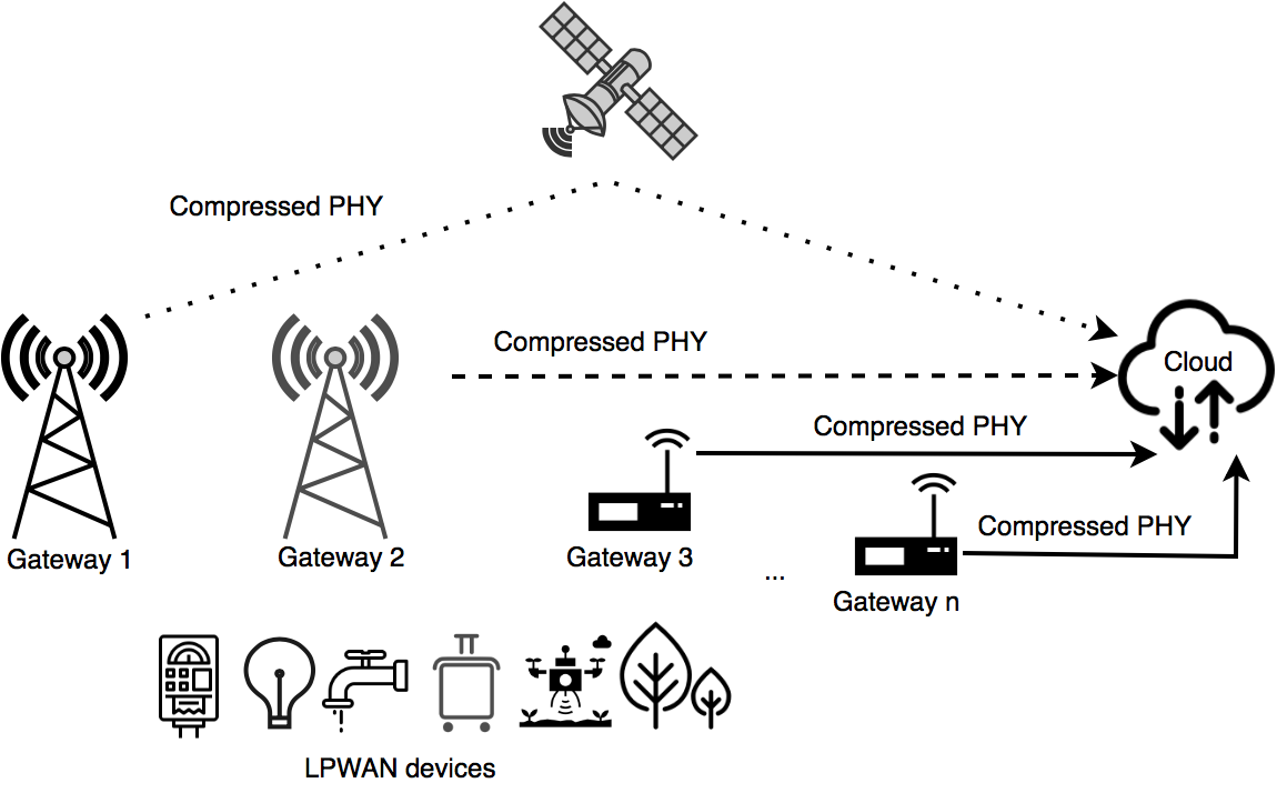
Therefore, PHY compression is the key enabler for LPWAN C-RAN. To this end, we propose a Compressive Sensing (CS)-based technique, called Nephalai222In ancient Greek mythology, Nephalai is the nymph of the clouds., to reduce the network bandwidth between gateways and the cloud. Fig. 1 shows the overview of Nephalai, which leverages the sparsity of the PHY for signal compression and (joint) reconstruction. Dictionaries and measurement matrices in Nephalai are custom-designed to exploit the structure of LoRa radio signals to achieve the best compression and reconstruction performance. Nephalai is designed to run in real-time and is implemented with SDR 333One limitation for Nephalai is the front-end hardware. Although our prototype discussed in Sec. 4 later can support 64 channels, if Nephalai is implemented on legacy front-end SX1257, it can support 8 channels only.. Our testbed evaluation in our campus has shown that, 1) up to 93.7% samples can be reduced without packet reception rate (PRR) reduction; 2) Nephalai can improve battery lifetimes to 1.7x with four gateways and 87.5% PHY samples compressed.
The contributions of this paper are as follows.
-
•
We propose a novel CS-based compression technique for cloud-assisted LPWAN that significantly reduces the bandwidth between the gateways and the cloud.
-
•
We propose a new dictionary to achieve high compression ratios without performance degradation. The proposed dictionary exploits the structure of LoRa radio signals, and achieves more than two orders-of-magnitude better sparse representation than standard Discrete Fourier transform (DFT) and Discrete Cosine transform (DCT) domains.
-
•
We implement a prototype of Nephalai with software-defined radios, and our empirical evaluation demonstrates its superior performance on embedded devices.
2. Related work
2.1. LPWAN, LoRa, LoRaWAN
LPWAN (Farrell, 2018; Sinha et al., 2017; Centenaro et al., 2016) has attracted much attention from both academia and industry in recent years. LoRaWAN (Sinha et al., 2017; Adelantado et al., 2017; Saari et al., 2018) is standardized by the LoRa Alliance for LPWAN on an unlicensed spectrum. LoRa (SELLER and Sornin, 2016; Knight, 2016; Robyns et al., 2018; Ghanaatian et al., 2019; Seller and Sornin, 2018; Vangelista et al., 2015) is the physical-layer foundation of LoRaWAN and defines modulation and radio communication. Recent research proposes slotted ALOHA based on a synchronization technique (Polonelli et al., 2019), which inspires us to synchronize LoRa symbols based on a similar scheme. In this paper, we focus on the sparsity of LoRa signals, and leverage the structure of LoRa in demodulation to optimize the performance of physical-layer compression.
2.2. C-RAN
C-RAN was proposed originally for cellular networks based on the concepts of centralization and virtualization for the baseband operations (China Mobile, 2011; Checko et al., 2015; Wübben et al., 2014; Beyene et al., 2017). The network can process demodulation in the cloud coherently, to exploit the diversity scheme. This refers to improving the reliability of wireless communication by using multiple radio channels (Brennan and D.G.BRENNAN, 1959). Such cloud-assisted decoding techniques in physical layers have also been investigated in Wi-Fi (Tan et al., 2009; Xie and Zhang, 2014) and LPWAN (Dongare et al., 2018; Hoeller et al., 2018; Beyene et al., 2017). The modification of gateways is transparent to the senders; therefore, there is no requirement for changes to the original embedded LoRa devices, which maintain their compatibility with the legacy devices.
2.3. Physical Layer Compression
One challenge of C-RAN is the high bandwidth requirement in transmitting I/Q streams from the edges to the cloud (Checko et al., 2015; Beyene et al., 2017). The Wyner-Ziv coding scheme leverages the correlation (side information) among receivers to use a finer quantizer in PHY compression (Xia et al., 2018; Park et al., 2014). However, the implementation of a distributed Wyner-Ziv compression is challenging mainly due to the complexity of obtaining the optimal joint compression codebook and the joint decompressing/decoding in the cloud (Peng et al., 2015). Alternatively, Compressive Sensing has been applied to achieve distributed front-haul compression (Rao and Lau, 2015; Wang et al., 2015). However, designing a sparse representation exploiting LoRa structures to improve compression performance has not yet been studied. To this end, the proposed custom-designed dictionary and measurement matrices achieve more than two orders-of-magnitude better performance than conventional DCT and DFT domains used in prior work.
Summary: Nephalai is partly inspired by Charm (Dongare et al., 2018), but makes significant contributions towards reducing the traffic between LoRaWAN gateways and the cloud. Charm focuses on improving SNR and battery life with multiple gateways, while our work Nephalai focuses on I/Q compression to further increase the capacity for PHY processing in the cloud. The compression technique used by Charm is the sum of consecutive samples in windows and generates data at a rate of 9 Mbps for a 500 kHz band. Taking our evaluation in Sec. 8.2.2 as an example, with 87.5% compression ratio, the data rate is 375 kbps for 125 kHz, equivalent to 1.5 Mbps for 500 kHz (more than 80% reduction compared to Charm), which can help Charm further reduce the data rates between the gateways and the cloud. Thus, the proposed compression technique is complementary to Charm. Furthermore, the proposed compression technique can also be applied in other scenarios such as multiple (or full) channel reception.
3. Background
3.1. LoRa physical layer
LoRa uses chirp spread-spectrum (CSS) as the method for modulation (SELLER and Sornin, 2016; Vangelista, 2017). The Spreading Factor () is usually defined as an integer from 7 to 12, representing the number of encoded bits per chirp symbol. Bandwidth () is the spectrum constraint of a channel, typically 125 or 500 kHz (LoRa Alliance, 2017). As discussed in Sec. 1, the LoRaWAN gateway uses 125 kHz for receiving packets from end devices, and thus in this paper we only focus on 125 kHz channels. LoRa utilizes time-shifted chirps in symbol modulation to carry information. The frequency of an up-chirp increases in a linear manner, while a down-chirp is the opposite.
3.2. Demodulation
The commonly used demodulation method is pulse compression, where the chirp symbol is first multiplied by a down-chirp in the time domain, and then processed with Fast Fourier transform (FFT) (SELLER and Sornin, 2016; Knight, 2016). The result is indicated by the most significant component in the frequency domain. If the symbol is not well segmented or unsynchronized, several peaks instead of one may show up, which results in demodulation failure. Open-source software such as gr-lora (Knight, 2016; Robyns et al., 2017) provide demodulation and decoding functions, while Nephalai focuses on PHY compression only.
3.3. Synchronized symbol
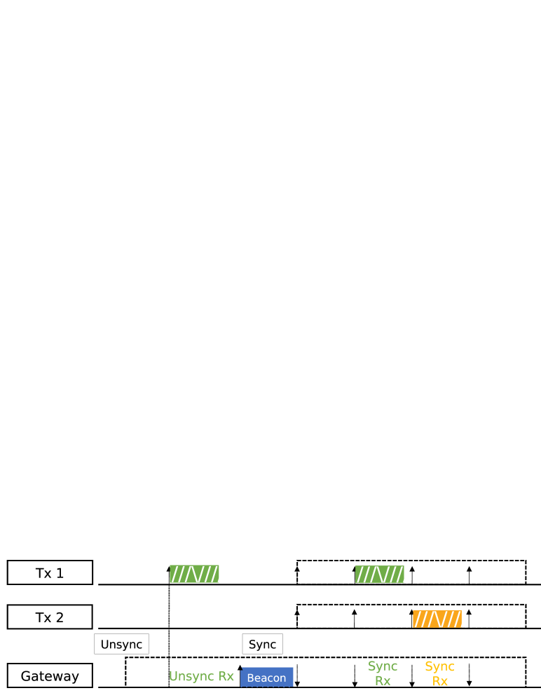
Inspired by LoRaWAN class B (LoRa Alliance, 2017) and slotted ALOHA (Polonelli et al., 2019), we can synchronize end nodes and gateways so gateways can receive with non-overlapped windows as shown in Fig. 2. However, perfect synchronization is neither possible nor necessary. Here, we use synchronized reception to improve the compression performance only, and further digital signal processing is performed in the cloud for fine-grain symbol segmentation. Thus, the synchronization error tolerance is high. This will be discussed further in Sec. 5.4.
4. Architecture
The Nephalai system has one cloud server equipped with GPU for minimization acceleration, and inexpensive single-board computers with SDRs as the edge gateways. Physical-layer radio samples are transferred from gateways to the cloud server via conventional Internet infrastructure.
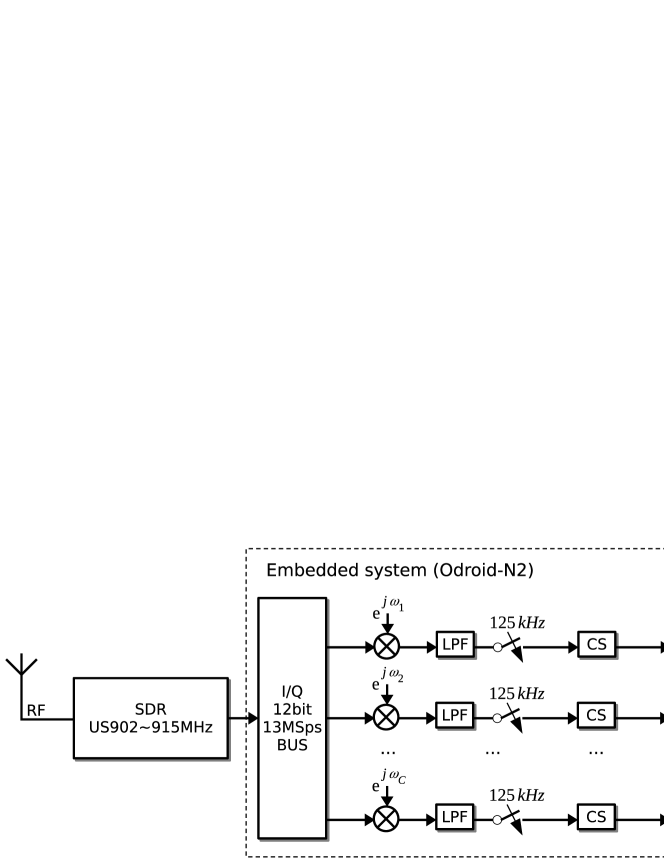
Fig. 3 depicts the overall architecture of Nephalai. The gateway clocks are synchronized via PPS from GPS modules with the accuracy of several microseconds. The accurate timestamp can help synchronize LoRa chirp symbols (see Fig. 2) and help the cloud server detect coherent LoRa packets easily. To analyze the complexity of our encoding algorithm in edge devices444We omit the complexity analysis of the proposed decoding algorithm in the cloud (i.e., minimization solver) since the cloud can be seen as having unlimited resources., suppose we have samples per symbol (this will be discussed in Sec. 5.4.2, in practice), samples per compressed vector, as the number of channels and as the number of low pass filter (LPF) taps. Then, the frequency conversion block together with LPF is , the down-sampler is , and the CS block is . The overall complexity in the edge devices is . Therefore, fewer taps for LPF and higher compression ratio for CS block can improve the performance of the embedded system. In order to support multiple 125 kHz channels as discussed in Sec. 1, the SDR of the gateway captures the whole 13 MHz LoRa spectrum, and the embedded system filters each channel and compresses using a shared measurement matrix. Compressed bits of each channel are packed together and uploaded to the cloud server. The cloud server then performs decompression and demodulation to recover the LoRa chirp symbols or jointly process all coherent symbols to improve their accuracy.
5. Compression
5.1. Lossless compression
We compare the compression performance of Nephelai against a conventional lossless compression LZ77-based algorithm, gzip (Misra et al., 2014). Gzip can only achieve a 7.5% compression ratio for Nyquist-sampled LoRa PHY, which means 92.5% of samples are not compressible. Such a low compression ratio is due to the fact that chirps spread across the whole spectrum, and general compression algorithms cannot exploit this sparsity in the frequency domain. In the following discussion, we consider the lossless compression ratio as the baseline, and investigate a novel CS-based algorithm to increase the compression ratio.
5.2. Compressive Sensing
CS is an information theory (Baraniuk, 2007; Donoho, 2006; Candès et al., 2006) that proposes an approach to recover high dimensional sparse signals from low dimensional measurements. Table 1 summarizes the mathematical symbols in this discussion. For a predefined dictionary , any signal can be a linear combination of as:
| (1) |
where is a coefficient vector of in the domain. If , given and , we can not solve Eq. (1) to obtain in a general form because it is an undetermined problem.
CS imposes the requirement that vector is sparse; namely, most of the elements in are zeros. Let denote the number of non-zeros in , then is sparse if . in CS is termed as sparsity. CS theory states that vector can be recovered accurately by solving the following stable minimization problem:
| (2) |
where is noise, and provided that satisfies the Restricted Isometry Property (RIP) condition. Note that RIP is only a sufficient but not a necessary condition. Therefore, -minimization may still be able to recover the sparse accurately, even if does not satisfy RIP. In fact, minimization has a rich history as it has been used to efficiently obtain useful sparse information in the signals from a compressed representation (Logan, 1965; Misra et al., 2011).
Common minimization algorithms are Matching Pursuit (MP), Orthogonal Matching Pursuit (OMP), Homotopy, -magic, etc., and the reconstruction performance of the algorithms depends on the sparsity of the signal and the incoherence between the measurement (compression) matrix and the signal itself, which is application dependent. Therefore, Nephelai uses a custom-designed dictionary to exploit the structure of LoRa signal and a custom-designed measurement matrix to maximize the incoherence between the matrix and the dictionary . Furthermore, Nephelai features a unique joint decoding process to exploit the spatial diversity of the LoRa signals received by the gateways in different locations to further improve the signal reconstruction (i.e., the decoding of the LoRa packets) performance.
| Symbol | Definition |
|---|---|
| CS dictionary | |
| CS measurement matrix | |
| Diagonal matrix for up-chirp | |
| Sampling rate | |
| LoRa symbol duration | |
| Raw samples before compression | |
| Compressed vector of measurement | |
| Sparse vector | |
| Compression ratio | |
| The degree of sparsity | |
| The number of items in dictionary | |
| The number of complex samples in LoRa symbol | |
| The length of compressed vector |
5.3. Dimension Reduction
Johnson-Lindenstrauss Lemma shows that random projections can preserve the distance of vector in a compressed domain , where with a high probability (Baraniuk, 2007) as:
| (3) |
where is a random compression matrix (recall that from Eq. (1), ). Since the sparsity of is (see Sec. 5.2), Wright et al. show that the minimum dimension of for a successful minimization recovery in practice is (Wright et al., 2009):
| (4) |
Substituting Eq. (3) to (2), minimization can be used to recover sparse vector from compressed measurement as:
| (5) |
Therefore, instead of uploading raw LoRa radio samples to the cloud, a Nephelai edge gateway uploads compressed measurements , and achieves a compression ratio of as:
| (6) |
5.4. Physical layer Compression
LoRa gateways can compress physical layer radio samples with a predefined measurement matrix (, where ) before transmitting the compressed samples () to the cloud server, where (joint) demodulation is performed based on the compressed signals by solving an minimization problem, i.e., Eq. (5).
For , we propose one dictionary for each covering two scenarios: 1) synchronized chirp symbol; 2) unsynchronized chirp symbol. Generally, scenario 2 is more common, and scenario 1 can be considered as a special case of scenario 2. Thus, a dictionary for unsynchronized should also be feasible for synchronized chirp symbols. However, based on our simulation and evaluation (see Sec.s 5.4.1 and 8.2.1), the compression ratio of the synchronized chirps is better than that of the unsynchronized, and thus we recommend the implementation of the synchronization mechanism for LoRaWAN to achieve a better compression performance.
5.4.1. Dictionary Design
Rao et al. have proposed the continuous, direct compression of physical layer radio samples with non-overlapped windows, in an attempt to fully recover the signal from the cloud (Rao and Lau, 2015). Normally, radio signals are sparse and compressible in conventional domains such as DFT and DCT. For LoRa, such methods are applicable but a more sparse domain can be obtained by exploiting the structure of the signals.
As discussed previously in Sec. 3.2, we demodulate the symbols by multiplying the symbols with an ideal down-chirp in the time domain and then by performing FFT on the de-chirped symbol. Both synchronized and unsynchronized blocks are sparse in frequency after being multiplied by a down-chirp. Here we define block as any -length clip of a LoRa PHY, where is equal to the duration of one chirp. A block is a combination of parts from two consecutive symbols. In the following sections, block and unsynchronized symbols are interchangeable.
First, by letting stand for the phase of an ideal up-chirp, we define matrix as having a diagonal made of an ideal down-chirp (opposite phase to an up-chirp),
| (7) |
Second, we define as the DFT matrix for ,
| (8) |
where . Therefore, we can write a sparse representation for any LoRa block as,
| (9) |
where represents the frequency domain and has only a few non-zeros. Comparing Eq. (9) and (1), we can then derive the dictionary as,
| (10) |
where is the matrix inversion. Therefore, the dictionary based on the sparsity of LoRa chirps is generated. We produce dictionaries according to , and store them in the cloud server.
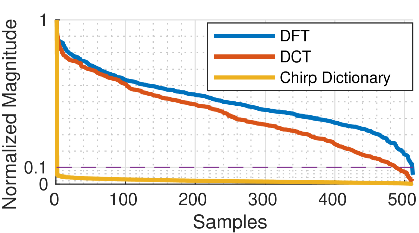
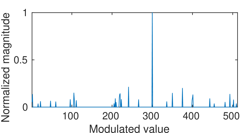
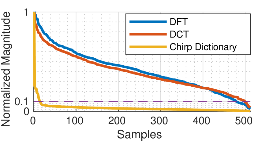
As a comparison with DFT, DCT, and the proposed chirp dictionary, Fig. 4(a) and 4(c) show the sparsity of typical synchronized and unsynchronized LoRa symbols () with channel noise in different domains by sorting the samples by order of magnitude. The fastest decay characteristic (or the smallest ) is observed in the proposed dictionary (), and therefore offers the most sparse representation; which means that the most accurate approximations (or LoRa symbol value estimations) can be obtained in this dictionary by using the smallest number of measurements (Eq. (4)). The sparsity in synchronized symbols is slightly better than the unsynchronized, which means that the accuracy in recovering synchronized symbols is better than the unsynchronized. The figure also shows that the proposed has two-order-of-magnitude fewer significant coefficients (e.g., the normalized magnitude is larger than 0.1) than those of DFT and DCT.
For the down-chirps in PHY, similar dictionaries can be obtained by replacing with a matrix with a diagonal made of an ideal up-chirp. Due to the fact that most chirps in LoRa PHY are up-chirps, we first solve -minimization with the up-chirp dictionary, and then try the down-chirp dictionary if no satisfactory result is obtained. Both dictionaries have similar features and performance. For brevity, we skip the discussion of the down-chirp dictionary.
5.4.2. Measurement Matrix
As discussed in CS theory (Baraniuk, 2007; Donoho, 2006; Candès et al., 2006), zero-mean Gaussian matrix and balance symmetric random Bernoulli matrix achieve favorable compression performance. For the computational efficiency on embedded devices, we choose random Bernoulli() as the measurement matrix with a fixed seed that is shared by both gateways and the cloud server.
Each symbol has samples, i.e. 128, 256, 512, 1024 for respectively. If we process separately, we have to compress PHY four times with , , , for each , which is against our motivation for compression. To solve this problem, we only measure with . For , we can simply concatenate two compressed vectors from . Similarly, we concatenate four compressed vectors for and eight compressed vectors for .
Thus, the gateway simply compresses every 128 samples with for each channel, and in the cloud the server concatenates compressed vectors for solving different s.
5.4.3. Compression ratio
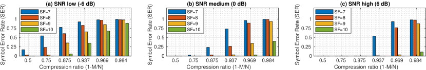
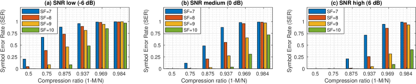
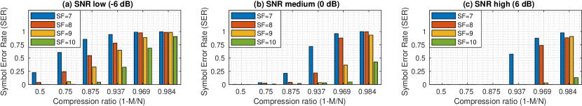
Compression ratios are defined by Eq. (6), and thus a smaller results in a better compression ratio. Theoretically, should be bounded on its lower end by Eq. (4). However, the noise from the original signal is hidden in compressed vectors, which may make it challenging to recover the original signals (i.e., minimization algorithm fails to solve Eq. (5)) . Thus, is not only bounded by Eq. (4), but is also affected by the signal SNR. We perform a simulation to investigate this phenomenon. As is an exponent of 2, to simplify the DSP process, is selected among exponents of 2 (e.g., 16, 32, 64, etc.). Here, we define low, medium and high SNRs as -6, 0 and 6 dB.
Fig. 5 shows that higher s outperform their lower counterparts, and increasing SNR can improve the compression ratio. When SNR is high, and can be compressed to and respectively without significant Symbol Error Rates (SERs), and the compression ratio is mainly bounded by Eq. (4). When SNR is medium and low, can be compressed to and respectively without significant SERs, and the compression ratio is mainly affected by SNR.
| SF7 | SF8 | SF9 | SF10 | |
|---|---|---|---|---|
| low SNR (-6 dB) | 1 | 1/2 | 1/4 | 1/8 |
| medium SNR (0 dB) | 1/4 | 1/8 | 1/16 | 1/32 |
| high SNR (6 dB) | 1/8 | 1/16 | 1/32 | 1/32 |
We summarize in Table 2 to represent the acceptable compression ratio if SER is small (e.g., ). Then, the empirical compression ratio based on Fig. 5 and Table 2 can be derived as:
| (11) |
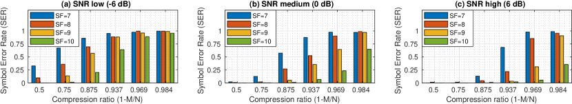
For unsynchronized symbols, as shown in Fig. 6, the performance is slightly poorer than that of the synchronized symbols. An unsynchronized symbol is composed of fractions of two consecutive chirp symbols (i.e. the last few samples from the first chirp and the first few samples from the second chirp). Thus, sparsity is increased from 1 to 2, and the lower bound Eq. (4) is slightly larger than that of the synchronized symbols. We modified Eq. (11) to select an appropriate compression ratio for unsynchronized symbols accordingly:
| (12) |
6. Nephelai in the cloud
6.1. Decoding (Single Gateway)
Most conventional -minimization algorithms require real-valued vectors and dictionaries, while communication systems always use complex values for I/Q modulation. To solve this problem we transform the vectors from complex-valued to real-valued as,
| (13) | ||||
| (14) | ||||
| (15) |
where . Then, we solve the problem with a real-valued -minimization algorithm for Eq. (5) as,
| (16) |
After obtaining the sparse vector with Eq. (16), we recover the complex-valued sparse vector by reversing Eq. (14), and thus we solve not only the magnitude but the phase of the chirp symbol.
Instead of using FFT for demodulation as described in Sec. 3.2, we proceed to estimate the most likely value by using residual . The residual for symbol candidate {0, 1, …, -1} is:
| (17) |
where operator indicates a vector containing the only coefficient related to candidates (the coefficients related to other candidates are set to be zeros). Then the final symbol estimation is determined by:
| (18) |
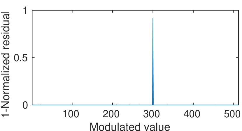
i.e., the with the minimal residual representing the modulation value. Fig. 4(d) shows the result of Nephelai decoding with Eq. (17) for a noisy chirp symbol. The highest peak (i.e., , suppose is normalized) represents the modulated value (e.g., 300) of the LoRa symbol correctly. Note that in , the phase of the highest peak may be used for radio-based ranging, which is beyond the scope of this paper.
6.2. Joint Decoding
We have discussed how Nephelai recovers value from single compressed measurement . In this section, we discuss how Nephelai exploits spatial diversity for gateways and improves performance with joint decoding.
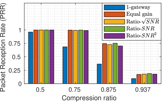
Suppose that we have gateways, and each gateway captures a transmitted copy of the same LoRa symbol independently. Next, Nephelai estimates the SNR level and produces residuals ( ) for gateways with Eq. (17). One of the ways to fuse these residuals among gateways is to perform a weighted summation. Based on the selection of combining weights, we have four algorithms: 1) weighted equally, aka. equal gain combining (EGC); 2) weighted by the ; 3) weighted by the aka. the maximum ratio combining (MRC), and 4) weighted by the . We evaluate the algorithms with collected samples by four gateways (further discussion in Sec. 8.2.3), and the results are shown in Fig. 7. All algorithms succeed in improving the PRR, and the algorithm weighted by the has the best performance especially when the compression ratio is high. Thus, we choose the MRC algorithm with SNR as the weight in the following evaluation.
Following this, the final symbol estimation is determined by:
| (19) |
Nephelai’s joint decoding algorithm can be found in Algorithm 1.
7. Prototype Implementation
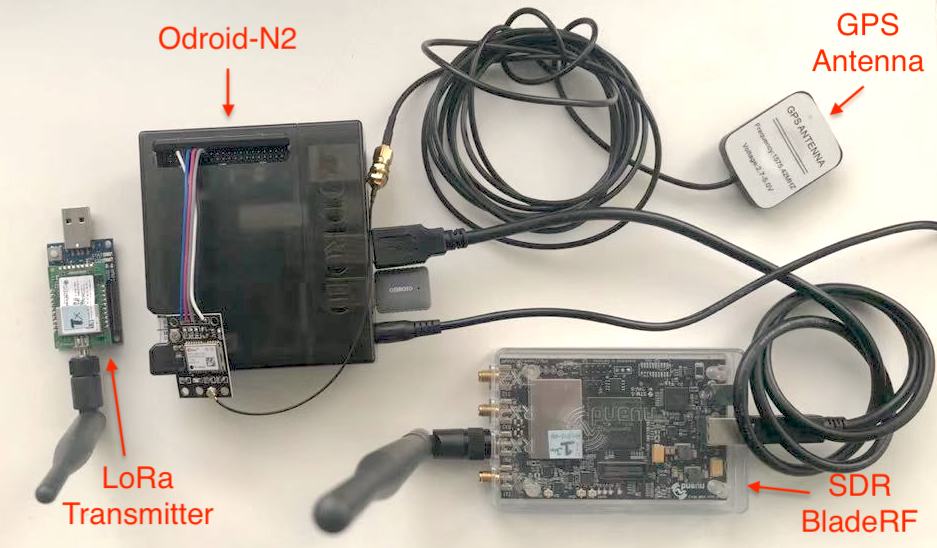
The Edge Gateway The Nephelai gateway shown in Fig. 8 has a radio front-end to capture signal samples on given LoRa channels, and an embedded computer to pre-process and compress the received signal samples before uploading to the cloud. In our prototype, we select BladeRF 2.0 SDR as the radio front-end to capture radio signals on LoRaWAN uplink channels (e.g., 902 MHz to 915 MHz in the USA). The output of SDR is a stream of and components, which can be regarded as complex values where denotes real and denotes imaginary parts respectively. The SDR can sample up to 61.44 mega samples per second (MSps), which are capable of capturing all the information in the whole 13 MHz upstream spectrum for USA defined by LoRaWAN. The Nyquist sampling rate for one channel is 125 kHz for complex samples (i.e. 250 kHz for real samples), and therefore the sample rate for 64 channels is 8 MSps (note the 75 kHz guard band between consecutive 125kHz channels, meaning that 8 MHz is for LoRa channels on a 13 MHz spectrum).
The SDR is connected to a Odroid-N2 (6-core single board computer with quad-core Cortex-A73@1.8GHz and dual-core Cortex-A53@1.9GHz) via a USB 3.0 port, through which the LoRa radio samples are transferred. Next, the Odroid-N2 processes (see Sec. 4) and compresses (see Sec. 5.4) the samples before transferring them to the cloud server. The sampling rate of our prototype is 13 MHz, which is sufficient to cover the 13 MHz LoRaWAN spectrum. Without loss of generality, we demonstrate the compression performance of Nephelai in a single LoRa uplink channel. If one single channel is compressible, so are 63 other channels.
We design and implement the software for Nephelai gateways, called gr-Nephelai based on the open-source software-defined ratio platform GNU-Radio. The frequency conversion and low pass filter shown in Fig. 3 are implemented in C++ and complied with single instruction multiple data (SIMD) optimization. Although there are 64 parallel branches in Fig. 3, we implement one block for all 64 channels instead of one block for each of the 64 channels to reduce the handover between blocks. The low-pass filter taps are selected as 47 to maintain real-time performance. The passband is designed to be 275 kHz, which works well to avoid inter-channel interference. When the gateway is running at full capacity (processing 64 channels), the overall CPU usage is approximately 60%.
The transmitter We program Multitech mDot555 MDot datasheet. https://www.multitech.com/brands/multiconnect-mdot , which comprises a LoRa wireless chip (SX1272), to periodically transmit 4 predefined bytes. The mDot with STM32F411RET uses 31 mA @100 MHz in the maximum power setting.
The Cloud Server Although the Nephelai cloud server can be any kind of general server, we use a 12-core CPU, 32 GB RAM and Nvidia 2070 GPU server in our prototype. It can perform -minimization algorithms for joint sparse LoRa signal reconstruction (i.e., LoRa packet decoding, see Sec. 6.2) in real-time.
8. Evaluation
8.1. Goals, Metrics and Methodologies
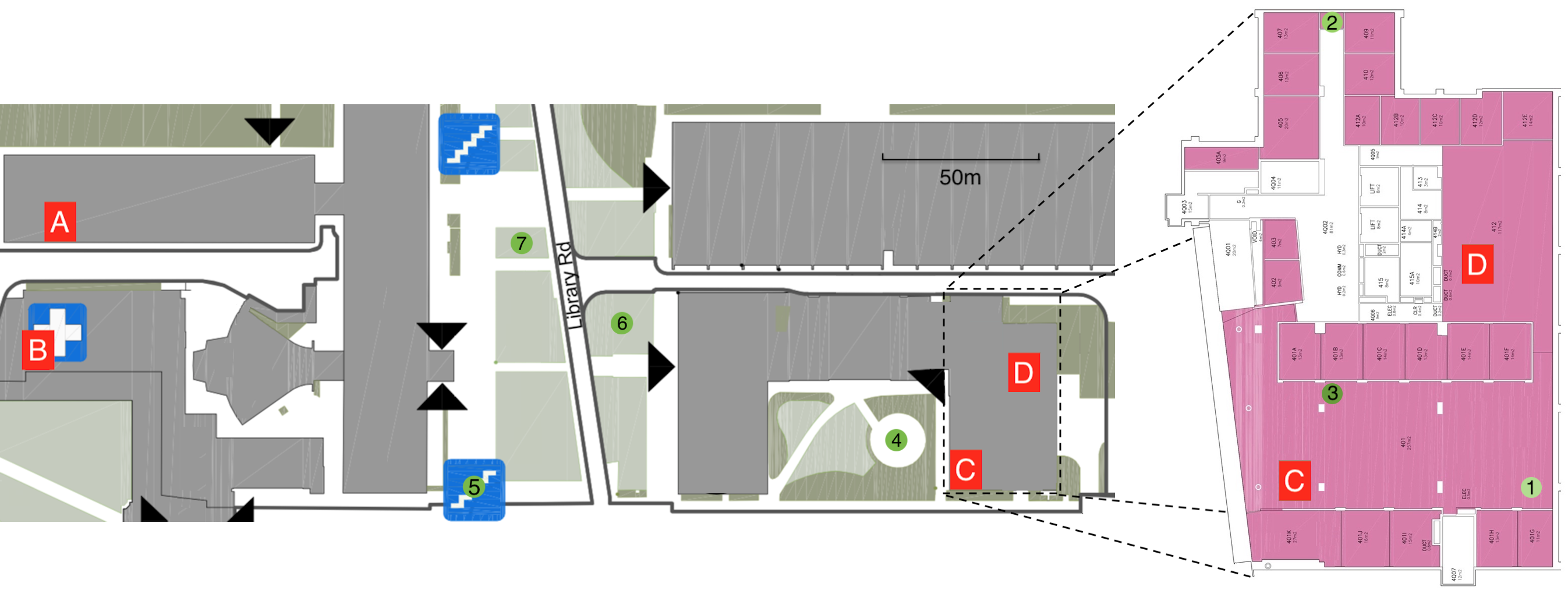
We deployed a Nephelai testbed with four Nephelai gateways (see Sec. 7) on our campus as shown in Fig. 9, where gateways are connected to a Nephelai cloud server (see Sec. 7) via Wi-Fi. We programmed seven mDots (see Fig. 8) as LoRa motes to periodically transmit predefined LoRa packets with power from 2 dBm to 14 dBm. We installed the LoRa motes in several representative positions in the campus to emulate real applications, and collected LoRa radio samples with each gateway simultaneously. During our evaluation, we collected more than one million LoRa chirp symbols among SF7 to SF10 to evaluate the performance of Nephelai.
We deployed LoRa motes to emulate real use cases. Mote-1 was an indoor temperature and humidity sensor; mote-2 acted as a passive infrared sensor (PIR), which functioned as an occupancy detector for the warehouse; mote-3 behaved as a smart water meter; mote-4 represented a simple outdoor weather station; mote-5 was attached to a stair handrail and counted people; and mote-6 and mote-7 measured the soil’s humidity to control a watering system for the lawn. In this evaluation we were not interested in application data but instead focused on PHY compression and potential battery lifetime improvement with joint decoding.
Nephelai is designed to implement the physical layer compression for cloud-assisted LoRa demodulation/decoding and to potentially improve transmitters’ energy efficiency. Therefore, the goals of our evaluation were:
-
(1)
to study whether Nephelai can reduce the network bandwidth of the front-haul in LPWAN C-RAN,
-
(2)
to study the impact of compression ratio () on the system’s performance, and
-
(3)
to study whether Nephelai can demonstrate similar energy improvements for the LoRa transmitter as the state-of-the-art LPWAN C-RAN, but with fewer front-haul data rates.
The metric for network bandwidth reduction is bits per second (bps), and that for energy reduction is battery lifetime extension. For methodologies, firstly, on the symbol level we evaluate how SNR and compression ratios affect SER in order to compare these with the simulation in Sec. 5.4.3. And then on packet level, we evaluated the PRR for single gateway scenarios with three LoRa motes and different power transmission levels. Furthermore, we evaluated the joint processing gain with four gateways and four transmitters to demonstrate that an equivalent SNR improvement can be achieved as the state-of-the-art (Dongare et al., 2018), i.e. to extend the battery lifetime to approximately 1.7x (equivalent to 2.3 dB SNR improvement) with four gateways, but with greater PHY compression. As there are different SFs resulting in different PRRs, we assumed that each SF was equal likely to be selected, and we calculated the expected PRR by averaging the PRRs of all SFs.
8.2. Empirical Results
8.2.1. Compression ratio
As discussed in Sec. 5.4.2, the compression ratio () is calculated using the dimension of measurement matrix (see Eq. (3)). In this section, we are only interested in how SNR affected the compression ratios, and in evaluating the compression ratio determination equations (i.e., Eq. (11) and (12)) for synchronized and unsynchronized symbols. We programmed motes-1/2/3 to transmit with power varying from 2 dB to 14 dB, and collected 50,000 synchronized and unsynchronized symbols respectively. We grouped symbols with respect to their low (-6 dB), medium (0 dB) and high (6 dB) SNR. Fig. 10 and 11 compare the compression performance of different SFs and SNRs based on the symmetric Bernoulli matrix() of and our proposed chirp dictionary (see Sec. 5.4). For example, for medium SNR (0 dB, i.e. the signal energy is equivalent to the noise floor) with synchronized symbols in Fig. 10, SF9 achieves an SER below 0.04 with a compression ratio of 93.7%. This represents approximately 16 times the bandwidth reduction in the C-RAN front-haul.
With a small SER value (e.g., ) as the reliable transmission threshold, we can summarize that the evaluation matches the simulation, when referring to in Table 3 based on Fig. 10, which compares Table 3 to Table 2. Therefore, we can use Eq. (11) in compression ratio selection. We observed similar patterns in the results of unsynchronized symbols in Eq. (12), however we omit the discussion here for brevity.
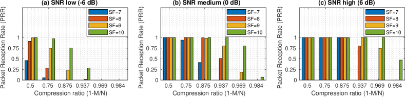
Furthermore, we performed PRR evaluation for synchronized packets with different SNRs, SFs and compression ratios as shown in Fig. 12. The LoRa packets transmitted in the evaluation had fixed length and their payloads consisted of 4 bytes (equivalent to 8 symbols). We defined PRR 75% as the threshold for reliable transmission (Le Dinh et al., 2007) and used it in our compression ratio selection. With the PRR criteria, Fig. 12 implies a similar compression ratio selection as that with SER in Table 3. Thus, we can use Eq. (11) in compression ratio selection. For unsynchronized symbols, similar to the discussion with SER, Eq. (12) is used for compression ratio selection.
| SF7 | SF8 | SF9 | SF10 | |
|---|---|---|---|---|
| low SNR (-6 dB) | 1 | 1/2 | 1/4 | 1/8 |
| medium SNR (0 dB) | 1/4 | 1/8 | 1/16 | 1/32 |
| high SNR (6 dB) | 1/8 | 1/16 | 1/32 | 1/32 |
In summary, compared to the benchmark of lossless algorithm LZ77 that achieves a compression ratio of 7.5% (see Sec. 5.1 for more details), the proposed approach can improve the compression ratio by approximately 10 times, depending on the parameter settings. For example, when SNR is high, a compression ratio up to 93.7% can be achieved for most SFs. Therefore, Nephelai achieves a significant reduction in traffic between gateways and the cloud server, which makes the cloud-assisted LoRa decoding scheme more scalable.
8.2.2. The performance of single gateway
In the single gateway evaluation using a real case, our goal was to compress PHY without PRR degradation. As discussed in Sec. 5, over-compression means that the minimization algorithm fails to solve Eq. (16), which increases SERs and decreases PRRs.
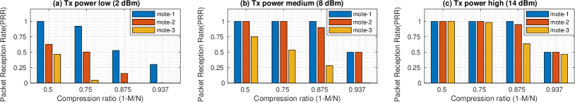
Firstly, as shown in Fig. 9, LoRaWAN transmitter motes-1, 2 and 3 were installed in a fixed position and were programmed to transmit 4 bytes with different spreading factors () at 2 dBm, 8 dBm and 14 dBm respectively. We collect packets via one gateway in either synchronized or unsynchronized mode. Secondly, with the algorithm proposed in Sec. 6.1, we calculated the PRR for different compression ratios. Instead of SER, we were more interested in PRR which describes the performance of end-to-end data transmissions. For example, if PRR is halved, the energy required to successfully deliver one packet is doubled, as the embedded node needs to transmit the packet twice. Therefore, the battery lifetime is halved. It is evident that PRR is more intuitive than SER in describing battery lifetime.
In our synchronized scenario, the compression ratio of 87.5% for motes-1 and 2 produced more than 90% PRR when power transmission was medium. For mote-3 in the basement, the compression ratio of 75% produced more than 50% PRR. We note that mote-3 was over-compressed with the compression ratio of 87.5% because the PRR is only 30% (see Fig. 13). Increasing power transmission could have increased the compression ratio for mote-3 from 75% to 87.5%, allowing it to maintain its PRR above 50% (Fig. 13(c)). According to the mDot datasheet, increasing power transmission from medium to high consumes 3.7% extra energy, which provides another acceptable option for scalability improvement.
In summary, Fig. 13 shows that PRR does not decrease with appropriate compression ratios, and increasing power transmission can improve the compression performance of Nephelai. Therefore, if all motes transmit at 14 dBm, we can select 87.5% as the compression ratio. For 64 channels, only Mbps is required for a single gateway in LPWAN C-RAN. Consequently, such a gateway can operate with bandwidth-limited Internet connections, widely extending the deployment region and application scenarios.
8.2.3. The performance of joint decoding
Compressing PHY without PRR degradation is possible as shown in Sec. 8.2.2 above. In this section, we evaluate the improvement of PRR with joint decoding under compression. Our goal was to achieve an equivalent performance to the state-of-the-art Charm system (i.e. 2.3 dB SNR improves with four gateways, see Sec. 1 for the details), but with less front-haul bandwidth between the gateway and the cloud.
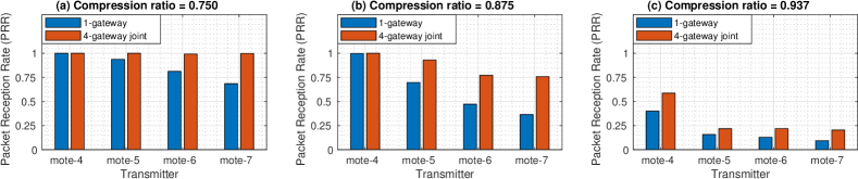
Firstly, we programmed motes-4,5,6 and 7 to be in synchronized mode and to send 4 byte messages periodically with high transmission power666We define 14 dBm as high transmission power in this paper, but in fact 14 dBm is a moderate choice compared to the maximum 22 dBm. (14 dBm). We collected LoRa radio samples simultaneously via gateways-A,B,C and D with different compression ratios (see Sec. 8.1 and Fig. 9 for testbed deployment in details). The number of packets for each SF was equal. Secondly, we calculated the PRR for single gateway decoding and coherent joint decoding with 4 gateways (according to the algorithm discussed in Sec. 6 under different compression ratios). We averaged PRR for all SFs to get an expected PRR as discussed previously in Sec. 8.1.
Fig. 14 shows how much improvement can be seen by joint decoding with four gateways compared to a single gateway. For battery-powered LoRa motes, the expected energy consumption per packet is reversely proportional to the PRR, and thus the expected battery lifetime is proportional to the PRR. When the compression ratio was 87.5%, mote-4 had PRR above 99% (since the position of mote-4 was very close to one of the gateways), while motes-5,6 and 7 had poor PRR with a single gateway. After joint decoding with four gateways, the PRR of mote-5 was improved from 70% up to 93%, while mote-6 went from 47% to 77%, and mote-7 went from 36% to 76%. The improvement factors are 1.33, 1.64 and 2.11 respectively, and the average is about 1.70. Therefore, on average, joint decoding extends battery lifetime to approximately 1.70 with four gateways when the compression ratio is 87.5%. We note that the least improved PRR occurred when the compression ratio is 75%, which is equivalent to a good quality, low power wireless link with a high C-RAN bit rate. Therefore, 87.5% is the recommended trade-off between compression ratio and PRR.
For compression up to 93.7%, single gateways experience severe packet loss for each mote. After joint decoding, the PRR of mote-4 was improved from 40% to 58%, while mote-5 improved from 16% to 22%, mote-6 from 13% to 22%, and mote-7 from 10% to 20%. However, this compression ratio is not recommended because most of the PRRs are still poor (i.e., less than 50%) even with joint decoding. Particularly, increasing the compression ratio from 87.5% to 93.7% for mote-4 causes PRR to decrease from more than 99% to 40%, meant that the mote had a shorter battery lifetime by approximately 60%. Finally, we note that when the compression ratio is 75%, with joint decoding, all PRRs are increased to more than 99%.
In summary, Nephelai with 4 gateways improves the PPR and the battery lifetime of a LoRa transmitter by 1.7 times on average, with the recommended compression ratio of 87.5% compared to a single gateway, which is equivalent to 2.3 dB SNR improvement (). The compression ratio of 87.5% also means that the PHY is compressed from 3 Mbps down to 375 kbps for one channel, while that of Charm is 2.25 Mbps per channel (see Sec. 1 for details). This demonstrates that Nephelai has similar functionality in improving the battery lifetime of embedded IoT devices as Charm (Dongare et al., 2018), while Nephelai reduces the bandwidth between gateways and the cloud by .
8.2.4. Cloud computing overhead
Solving minimization is computationally intensive, but can be handled with parallel implementation using multi-threading, GPU, FPGA, etc. in the cloud. If the demodulation of one symbol is performed in real-time, and the delay caused by data transmission and computation (from the gateway to the cloud, and back to the gateway) meets the LoRaWAN requirement for an ACK, the Nephelai system is feasible.
We evaluated cloud computing overhead by performing single-threading tests with MATLAB on Intel Core i7-8700 CPU @ 3.20GHz with 32GB RAM for 1000 times calculation per case as shown in Table. 4. The worst case is SF10 with a 50% compression ratio. One symbol for SF10 can be solved in less than 500 ms with a single thread. The length of one symbol for SF10 is 8.2 ms, and in 500 ms the gateway can receive at most 61 of these symbols. Therefore, a 64 core server can be used in the cloud to dispatch demodulation tasks to each core in order to obtain real-time demodulation within 500 ms. For other SFs and compression ratios, the computational demand is even lower. Note that the computation can be further optimised for higher efficiency.
LoRaWAN has a relatively loose requirement for ACK delays due to low bit rates (e.g., 300 bps). There is a parameter called ACK_TIMEOUT in the LoRaWAN settings with a default value of ”s ( i.e., a random delay between 1 and 3 seconds)”. The demodulation latency is less than 500ms as discussed above, and the Internet latency is typically less than 100 milliseconds one way. Processing latency caused by gateways and radio propagation delays can be ignored. Thus, an ACK can easily be generated in one second to meet the LoRaWAN requirements discussed above.
| SF7 | SF8 | SF9 | SF10 | |
|---|---|---|---|---|
| 0.5 | 5.1 2.5 | 10.82.7 | 66.8 61.9 | 297.7180.5 |
| 0.75 | 2.0 0.6 | 4.7 1.0 | 16.313.7 | 71.232.6 |
| 0.875 | 1.0 0.2 | 2.2 0.4 | 5.5 3.3 | 16.16.1 |
| 0.937 | 0.6 0.1 | 1.1 0.2 | 2.3 0.9 | 5.11.8 |
8.2.5. Influence of concurrent transmission
Theoretically, multi-channel concurrent transmission may reduce the system’s performance by leaking energy as noise to other channels. However, through our evaluation, we have found that concurrent transmission does not cause system degradation.
We established a LoRa transmitter that sent packets with SF=8 and a packet length of 41.5 ms every 50 ms periodically in one 125kHz channel, and another transmitter that sent in the neighbouring channels. We calculated the PRR based on the collected samples in different interference environments: no interference, concurrent transmission on a +200kHz channel, concurrent transmission on a +400kHz channel, … , and concurrent transmission on a +1000kHz channel. Our evaluation results show that no significant PRR reduction is caused by concurrent transmissions. If we have a well designed filter for each 125kHz channel, the noise caused by concurrent transmissions can be prevented. In summary, Nephelai is robust against the interference caused by concurrent transmissions.
9. Conclusion
We introduce Nephelai, which is based on CS-theory, to reduce the bandwidth requirement between edge gateways and the cloud server for cloud-assisted LoRaWAN. Nephelai exploits: 1) the physical layer structure of LoRa symbols for a custom designed dictionary to significantly improve its compression performance, 2) the relationship between compression ratios, SNR and SFs to select an appropriate compression ratio, and 3) radio signal spatial diversity by joint decoding to improve the PRR as well as the battery lifetime for end devices. Our empirical results with an edge gateway prototype consisting of SDR and Odroid-N2 show that Nephelai can reduce traffic between gateways and cloud servers by up to 93.7% and can significantly improve the scalability of cloud assisted LoRaWAN.
References
- (1)
- Adelantado et al. (2017) Ferran Adelantado, Xavier Vilajosana, Pere Tuset-Peiro, Borja Martinez, Joan Melia-Segui, and Thomas Watteyne. 2017. Understanding the Limits of LoRaWAN. IEEE Communications Magazine 55, 9 (2017), 34–40. https://doi.org/10.1109/MCOM.2017.1600613 arXiv:1607.08011
- Baraniuk (2007) Richard Baraniuk. 2007. Compressive Sensing [Lecture Notes]. IEEE Signal Processing Magazine 24, 4 (jul 2007), 118–121. https://doi.org/10.1109/MSP.2007.4286571
- Beyene et al. (2017) Yihenew Dagne Beyene, Riku Jantti, Olav Tirkkonen, Kalle Ruttik, Sassan Iraji, Anna Larmo, Tuomas Tirronen, and Johan Torsner. 2017. NB-IoT Technology Overview and Experience from Cloud-RAN Implementation. IEEE Wireless Communications 24, 3 (jun 2017), 26–32. https://doi.org/10.1109/MWC.2017.1600418
- Bor et al. (2016) Martin Bor, Utz Roedig, Thiemo Voigt, and Juan M Alonso. 2016. Do LoRa low-power wide-area networks scale?. In MSWiM 2016 - Proceedings of the 19th ACM International Conference on Modeling, Analysis and Simulation of Wireless and Mobile Systems. 59–67. https://doi.org/10.1145/2988287.2989163
- Brennan and D.G.BRENNAN (1959) D. G. Brennan and D.G.BRENNAN. 1959. Linear Diversity Combining Technique. Proceedings of the IRE 10, 6 (jun 1959), 1075–1102. https://doi.org/10.1109/JRPROC.1959.287136
- Candès et al. (2006) Emmanuel J. Candès, Justin Romberg, and Terence Tao. 2006. Robust uncertainty principles: Exact signal reconstruction from highly incomplete frequency information. IEEE Transactions on Information Theory 52, 2 (sep 2006), 489–509. https://doi.org/10.1109/TIT.2005.862083 arXiv:math/0409186
- Centenaro et al. (2016) Marco Centenaro, Lorenzo Vangelista, Andrea Zanella, and Michele Zorzi. 2016. Long-range communications in unlicensed bands: The rising stars in the IoT and smart city scenarios. IEEE Wireless Communications 23, 5 (2016), 60–67.
- Checko et al. (2015) Aleksandra Checko, Henrik L. Christiansen, Ying Yan, Lara Scolari, Georgios Kardaras, Michael S. Berger, and Lars Dittmann. 2015. Cloud RAN for Mobile Networks - A Technology Overview. IEEE Communications Surveys & Tutorials 17, 1 (2015), 405–426. https://doi.org/10.1109/COMST.2014.2355255
- China Mobile (2011) China Mobile. 2011. C-RAN: the road towards green RAN. White Paper, ver 2.5 5 (2011), 15–16.
- Dongare et al. (2018) Adwait Dongare, Revathy Narayanan, Akshay Gadre, Anh Luong, Artur Balanuta, Swarun Kumar, Bob Iannucci, and Anthony Rowe. 2018. Charm: Exploiting Geographical Diversity Through Coherent Combining in Low-power Wide-area Networks. In Proceedings of the 17th ACM/IEEE International Conference on Information Processing in Sensor Networks (IPSN ’18). IEEE Press, Piscataway, NJ, USA, 60–71. https://doi.org/10.1109/IPSN.2018.00013
- Donoho (2006) David L. Donoho. 2006. For most large underdetermined systems of linear equations the minimal l1-norm solution is also the sparsest solution. Communications on Pure and Applied Mathematics 59, 6 (jun 2006), 797–829. https://doi.org/10.1002/cpa.20132
- Farrell (2018) S Farrell. 2018. Low-Power Wide Area Network (LPWAN) Overview. Technical Report. RFC Editor. 1–43 pages. https://doi.org/10.17487/RFC8376
- Gadre et al. (2020) Akshay Gadre, Revathy Narayanan, Anh Luong, Anthony Rowe, Bob Iannucci, and Swarun Kumar. 2020. Frequency Configuration for Low-Power Wide-Area Networks in a Heartbeat. In 17th USENIX Symposium on Networked Systems Design and Implementation (NSDI 20). 339–352.
- Georgiou and Raza (2017) Orestis Georgiou and Usman Raza. 2017. Low Power Wide Area Network Analysis: Can LoRa Scale? IEEE Wireless Communications Letters 6, 2 (oct 2017), 162–165. https://doi.org/10.1109/LWC.2016.2647247 arXiv:1610.04793
- Ghanaatian et al. (2019) Reza Ghanaatian, Orion Afisiadis, Matthieu Cotting, and Andreas Burg. 2019. LoRa digital receiver analysis and implementation. In ICASSP 2019-2019 IEEE International Conference on Acoustics, Speech and Signal Processing (ICASSP). IEEE, 1498–1502.
- Hoeller et al. (2018) Arliones Hoeller, Richard Demo Souza, Onel L Alcaraz López, Hirley Alves, Mario de Noronha Neto, and Glauber Brante. 2018. Analysis and performance optimization of LoRa networks with time and antenna diversity. IEEE Access 6 (2018), 32820–32829.
- Knight (2016) Matthew Knight. 2016. Decoding LoRa : Realizing a Modern LPWAN with SDR. In Proceedings of the 6th GNU Radio Conference,, Vol. 1.
- Le Dinh et al. (2007) Tuan Le Dinh, Wen Hu, Pavan Sikka, Peter Corke, Leslie Overs, and Stephen Brosnan. 2007. Design and deployment of a remote robust sensor network: Experiences from an outdoor water quality monitoring network. In 32nd IEEE Conference on Local Computer Networks (LCN 2007). IEEE, 799–806.
- Liando et al. (2019) Jansen C. Liando, Amalinda Gamage, Agustinus W. Tengourtius, and Mo Li. 2019. Known and unknown facts of LoRa: Experiences from a large-scale measurement study. ACM Transactions on Sensor Networks 15, 2 (2019). https://doi.org/10.1145/3293534
- Logan (1965) B. Logan. 1965. Properties of high-pass signals. Ph.D. Dissertation. Columbia University.
- LoRa Alliance (2017) LoRa Alliance. 2017. LoRaWAN 1.1 Specification. LoRa Alliance 1.1 (2017), 101. https://lora-alliance.org/resource-hub/lorawantm-specification-v11
- Misra et al. (2014) Prasant Misra, Wen Hu, Yuzhe Jin, Jie Liu, Amanda Souza De Paula, Niklas Wirström, and Thiemo Voigt. 2014. Energy efficient GPS acquisition with Sparse-GPS. In IPSN 2014 - Proceedings of the 13th International Symposium on Information Processing in Sensor Networks (Part of CPS Week). IEEE, 155–166. https://doi.org/10.1109/IPSN.2014.6846749
- Misra et al. (2011) Prasant Kumar Misra, Diethelm Ostry, Navinda Kottege, and Sanjay Jha. 2011. TWEET: an envelope detection based broadband ultrasonic ranging system. In Proceedings of the 14th ACM international conference on Modeling, analysis and simulation of wireless and mobile systems. ACM, 409–416. https://doi.org/10.1145/2068897.2068967
- Park et al. (2014) Seok Hwan Park, Osvaldo Simeone, Onur Sahin, and Shlomo Shamai Shitz. 2014. Fronthaul compression for cloud radio access networks: Signal processing advances inspired by network information theory. IEEE Signal Processing Magazine 31, 6 (nov 2014), 69–79. https://doi.org/10.1109/MSP.2014.2330031
- Peng et al. (2015) Mugen Peng, Chonggang Wang, Vincent Lau, and H. Vincent Poor. 2015. Fronthaul-Constrained Cloud Radio Access Networks: Insights and Challenges. IEEE Wireless Communications 22, 2 (mar 2015), 152–160. https://doi.org/10.1109/MWC.2015.7096298 arXiv:1503.01187
- Polonelli et al. (2019) Tommaso Polonelli, Davide Brunelli, Achille Marzocchi, and Luca Benini. 2019. Slotted ALOHA on LoRaWAN-design, analysis, and deployment. Sensors (Switzerland) 19, 4 (2019). https://doi.org/10.3390/s19040838
- Rao and Lau (2015) Xiongbin Rao and Vincent K.N. Lau. 2015. Distributed fronthaul compression and joint signal recovery in cloud-RAN. IEEE Transactions on Signal Processing 63, 4 (feb 2015), 1056–1065. https://doi.org/10.1109/TSP.2014.2386290
- Robyns et al. (2017) Pieter Robyns, Quax Peter, Lamotte Wim, and Thenaers William. 2017. gr-lora: An efficient LoRa decoder for GNU Radio. https://doi.org/10.5281/zenodo.853201
- Robyns et al. (2018) Pieter Robyns, Peter Quax, Wim Lamotte, and William Thenaers. 2018. A multi-channel software decoder for the LoRa modulation scheme.
- Saari et al. (2018) M. Saari, A. Muzaffar bin Baharudin, P. Sillberg, S. Hyrynsalmi, and W. Yan. 2018. LoRa — A survey of recent research trends. In 2018 41st International Convention on Information and Communication Technology, Electronics and Microelectronics (MIPRO). IEEE, Opatija, 0872–0877. https://doi.org/10.23919/MIPRO.2018.8400161
- SELLER and Sornin (2016) Olivier BA SELLER and Nicolas Sornin. 2016. Low power long range transmitter. US Patent 9,252,834.
- Seller and Sornin (2018) Olivier Bernard André Seller and Nicolas Sornin. 2018. Low complexity, low power and long range radio receiver. US Patent App. 15/620,364.
- Sinha et al. (2017) Rashmi Sharan Sinha, Yiqiao Wei, and Seung-Hoon Hwang. 2017. A survey on LPWA technology: LoRa and NB-IoT. Ict Express 3, 1 (2017), 14–21.
- Talla et al. (2017) Vamsi Talla, Mehrdad Hessar, Bryce Kellogg, Ali Najafi, Joshua R. Smith, and Shyamnath Gollakota. 2017. LoRa Backscatter: Enabling The Vision of Ubiquitous Connectivity. Proceedings of the ACM on Interactive, Mobile, Wearable and Ubiquitous Technologies 1, 3 (2017), 105. https://doi.org/10.1145/3130970 arXiv:1705.05953
- Tan et al. (2009) Kun Tan, He Liu, Ji Fang, Wei Wang, Jiansong Zhang, Mi Chen, and Geoffrey M. Voelker. 2009. SAM: Enabling Practical Spatial Multiple Access in Wireless LAN. In Proceedings of the 15th annual international conference on Mobile computing and networking - MobiCom ’09 (MobiCom ’09). ACM, New York, NY, USA, 49. https://doi.org/10.1145/1614320.1614327
- Vangelista (2017) Lorenzo Vangelista. 2017. Frequency Shift Chirp Modulation: The LoRa Modulation. IEEE Signal Processing Letters 24, 12 (dec 2017), 1818–1821. https://doi.org/10.1109/LSP.2017.2762960
- Vangelista et al. (2015) Lorenzo Vangelista, Andrea Zanella, and Michele Zorzi. 2015. Long-range IoT technologies: The dawn of LoRaTM. In Lecture Notes of the Institute for Computer Sciences, Social-Informatics and Telecommunications Engineering, LNICST, Vol. 159. Springer, Cham, 51–58.
- Wang et al. (2015) Yingjie Wang, Zhiyong Chen, and Manyuan Shen. 2015. Compressive sensing for uplink cloud radio access network with limited backhaul capacity. In 2015 4th International Conference on Computer Science and Network Technology (ICCSNT), Vol. 1. IEEE, 898–902.
- Wright et al. (2009) J. Wright, A. Y. Yang, A. Ganesh, S. S. Sastry, and Y. Ma. 2009. Robust Face Recognition via Sparse Representation. IEEE Transactions on Pattern Analysis and Machine Intelligence 31, 2 (Feb 2009), 210–227. https://doi.org/10.1109/TPAMI.2008.79
- Wübben et al. (2014) Dirk Wübben, Peter Rost, Jens Steven Bartelt, Massinissa Lalam, Valentin Savin, Matteo Gorgoglione, Armin Dekorsy, and Gerhard Fettweis. 2014. Benefits and impact of cloud computing on 5g signal processing: Flexible centralization through cloud-RAN. IEEE Signal Processing Magazine 31, 6 (nov 2014), 35–44. https://doi.org/10.1109/MSP.2014.2334952
- Xia et al. (2018) Wenchao Xia, Jun Zhang, Tony Q.S. Quek, Shi Jin, and Hongbo Zhu. 2018. Joint optimization of fronthaul compression and bandwidth allocation in uplink H-CRAN with large system analysis. IEEE Transactions on Communications 66, 12 (2018), 6556–6569. https://doi.org/10.1109/TCOMM.2018.2861407
- Xie and Zhang (2014) Xiufeng Xie and Xinyu Zhang. 2014. Scalable user selection for MU-MIMO networks. In Proceedings - IEEE INFOCOM. 808–816. https://doi.org/10.1109/INFOCOM.2014.6848008
- Xu et al. (2019) Weitao Xu, Jun Young Kim, Walter Huang, Salil S. Kanhere, Sanjay K. Jha, and Wen Hu. 2019. Measurement, Characterization, and Modeling of LoRa Technology in Multifloor Buildings. IEEE Internet of Things Journal 7, 1 (2019), 298–310. https://doi.org/10.1109/jiot.2019.2946900 arXiv:1909.03900