Resonant spin amplification meets electron spin resonance in -GaAs
Abstract
Periodic excitation of electron spin polarization by consecutive laser pulses in phase with Larmor spin precession about a magnetic field results in resonant spin amplification (RSA). We observe a drastic modification of RSA in -doped bulk GaAs under the influence of external oscillating magnetic field. We find a double-peaked electron spin resonance instead of a single-peaked resonance expected without optical pumping. The frequency splitting increases linearly with amplitude of field oscillations, while the spin deviation increases quadratically. Moreover, we show that the oscillating field can both significantly suppress RSA and induce new conditions for resonance. Using quaternions to describe spin rotations, we develop a theory that simultaneously considers spin precession, decay, and amplification and reproduces the entire set of the experimental data. Using the radio-frequency field allows one to control the conditions of RSA and achieve fine tuning of average spin polarization without modifying the parameters of optical pumping.
I Introduction
The electron spin system in a magnetic field is characterized by the Larmor frequency of spin precession, which also determines the Zeeman energy splitting between the spin eigenstates. Being subject to an additional radiofrequency (rf) or microwave magnetic field oscillating at a frequency , the spin system can experience a resonance when , referred to as Electron paramagnetic resonance or Electron spin resonance (ESR) Poole (1996). In this case the rf field is resonantly absorbed while synchronizing precession of individual spins, i.e., driving precession of the macroscopic spin polarization. ESR can also be detected optically, e.g., by measuring the degree of circular polarization of photoluminescence, which significantly increases sensitivity of the method Cavenett (1981). Usually, ESR affects only the spin polarization given by the difference between the populations of Zeeman-splitted spin sublevels in thermal equilibrium, which is fairly small. The spin polarization affected by ESR can be enhanced by an additional circularly-polarized optical pumping Hermann and Lampel (1971); Cavenett (1981); Belykh et al. (2020a) thanks to the optical orientation effect Meier and Zakharchenya (1984).
In fact, for the special case of a periodic optical pumping another resonance can appear, referred to as Resonant spin amplification (RSA) Kikkawa and Awschalom (1998). It takes place when the precessing spin created by a laser pulse comes in phase with the spin created by the next pulse, i.e., when , where is the repetition rate of optical pulses and is an integer number. RSA reveals itself as resonant enhancement of spin polarization and is traditionally detected in pump-probe Faraday/Kerr rotation experiments Yakovlev and Bayer (2017); Yugova et al. (2009); Kugler et al. (2011); Griesbeck et al. (2012); Hernandez et al. (2014); Macmahon et al. (2019); Schering et al. (2019).
In this work, we bring together RSA and ESR resonances by applying a rf field to the -doped bulk GaAs sample periodically pumped by laser pulses. To detect the spin polarization, we measure Faraday rotation of a linearly polarized component of the same laser pulses in a single-beam experiment similarly to the method developed in the works Saeed et al. (2018); Kotur et al. (2018). We find that in the RSA regime the behavior of ESR is unusual. In particular, spin polarization is quadratic on the rf field amplitude and shows a drastically different dependence on and . The rf field can either drive spin precession out of the RSA resonance or tune it into the RSA resonance. We develop a theory of the combined RSA-ESR resonance using quaternions to describe spin rotations. The theory results in a single analytical equation that fully reproduces the experimental observations.
II Experimental details
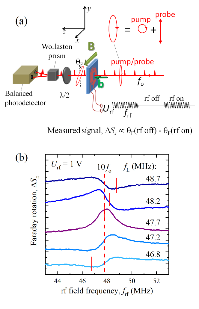
The scheme of the experiment is shown in Fig. 1(a). The sample under study is a 350-m-thick Si-doped GaAs bulk wafer with electron concentration cm-3 near the metal-insulator transition Belykh et al. (2016, 2019, 2020a). The sample is placed in the variable temperature cryostat. The temperature in all experiments K. Using the permanent magnet placed outside the cryostat on a controllable distance, a constant magnetic field up to 15 mT is applied along -axis, perpendicular to the direction of light propagation (-axis) and to the sample normal (Voigt geometry). The optical spin pumping and probing is performed by the same laser beam, the initial polarization of which is slightly elliptical. The circular and linear components of the elliptically polarized beam can be considered as the simultaneous pump and probe, respectively, for the electron spin. We use 2-ps-long optical pulses generated by the Ti:Sapphire laser with repetition rate MHz. To achieve multiple RSA peaks in the limited range of magnetic fields, we reduce the repetition rate of optical pulses 16 times to MHz (repetition period ns) by selecting single pulses with the acousto-optical pulse picker synchronized with the laser. The Faraday rotation of the linear component of laser polarization after transmission through the sample is analyzed using the Wollaston prism, splitting the beam into the two orthogonally polarized beams of approximately equal intensities, which are registered by the balanced photodetector. The laser wavelength is set to 827 nm.
To observe the effect of ESR on the measured Faraday rotation, the rf magnetic field is applied along the sample normal (-axis) using the small ( mm-inner and mm-outer diameter) coil near the sample surface. The current through the coil is driven by the function generator, which creates sinusoidal voltage with frequency up to 150 MHz and amplitude up to 10 V. The generator output is modulated at frequency 100 kHz, so that a 5-s train of sinusoidal voltage follows 5 s of zero voltage. Using the lock-in amplifier, the signal from the balanced detector is registered synchronously at modulation frequency 100 kHz. Thus, we measure the difference between the Faraday rotation for the rf field switched off and on, which is proportional to the corresponding difference in the component of the spin polarization, .
III Experimental results
In this study we deal with spins of resident electrons in -doped GaAs. Their spin lifetime at low magnetic fields and low temperatures ns Belykh et al. (2016) is much longer than the recombination time of photocreated electrons and holes ( ns). Here , , and are the longitudinal, transverse, and inhomogeneous transverse spin relaxation times, respectively. When a circularly polarized (component of) laser pulse excites a spin-polarized electron-hole pair, the spin relaxation time of the hole is much shorter than that of the electron and about the recombination time. Thus, the hole with almost equal probability can recombine with the photocreated or the resident electron of any spin polarization, while the spin of the photocreated electron stays in the system. In this way each optical pulse introduces in the system a spin polarization directed along the sample normal (-axis) with repetition rate . When the permanent magnetic field is applied to the sample, the electron spins precess with the Larmor frequency , where is the electron factor in bulk GaAs and is the Bohr magneton. If the magnetic field fulfills the resonance condition , where is an integer, RSA takes place Kikkawa and Awschalom (1998). RSA for the studied sample was observed in the work Belykh et al. (2016) with the separate pump and probe beams. Here we study a change in the spin polarization induced by the rf field, in particular in the RSA regime. To do this, we measure as a function of the rf frequency , which is referred to as the ESR spectrum.
Figure 1(b) shows the ESR spectra for different values of the permanent magnetic field , corresponding to different for the relatively small rf voltage V. The Larmor frequency is changed in the vicinity of the RSA resonance . Out of the resonance the ESR spectra exhibit a derivative-like peculiarity at . When approaches , the peculiarity is enhanced and transforms to the pronounced symmetric peak with the half width at half maximum (HWHM) MHz, which gives an estimate for the spin dephasing time (it will be seen below that, in general, is also contributed by the rf field amplitude and ). Thus, the effect of rf on spin polarization is most pronounced in the RSA regime.
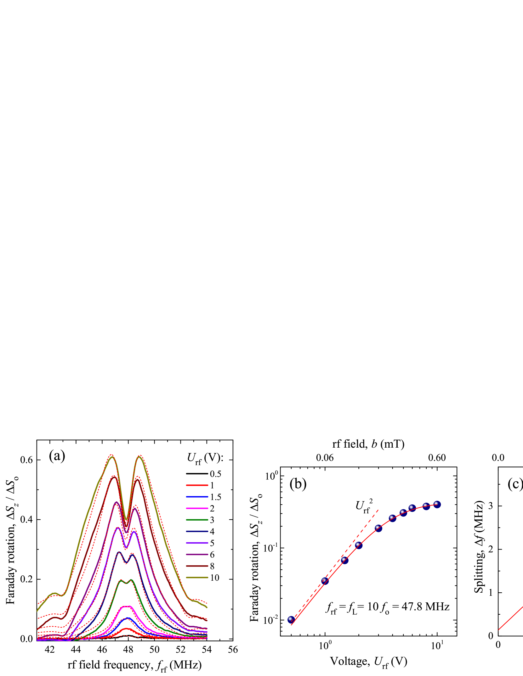
Next we increase the rf field amplitude via the voltage applied to the rf coil and observe transformation of the ESR spectrum [Fig. 2(a)]. These experiments are performed in the RSA regime, . With increasing the ESR peak amplitude rapidly increases and the peak broadens. At even higher rf voltages the splitting in the ESR peak appears, which we attribute to the Rabi splitting Rabi (1937). The frequency splitting is proportional to [Fig. 2(c)], which is expected for the Rabi splitting. Figure 2(b) shows the dependence of the spin polarization on the rf voltage for the resonant case . Spin polarization increases quadratically and then the dependence flattens. Note that, usually the ESR signal linearly increases with and oscillates at higher Belykh et al. (2019).
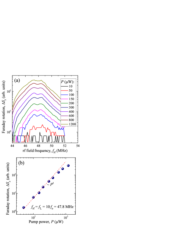
It is instructive to check the behavior of the ESR spectrum with increasing the power of optical pumping in the RSA regime [Fig. 3(a)]. The spectrum amplitude strongly increases with , while the form of the spectrum remains almost unchanged. Only at large the spectrum somewhat broadens, which may be attributed to a decrease of the spin dephasing time at high optical pumping Crooker et al. (2009); Petrov et al. (2018). The signal at the center of the ESR peak, for , increases quadratically with and slightly saturates at high [Fig. 3(b)]. This behavior is expected. Indeed, the spin polarization is proportional, on the one hand, to the pump power and, on the other hand, to the probe power. Here each laser pulse pumps the spin system and simultaneously probes it, so the signal is proportional to . And vice versa, the quadratic dependence confirms that we work in the regime of a one-beam simultaneous pumping and probing, i.e., that optical pumping plays the major role in our experiments.
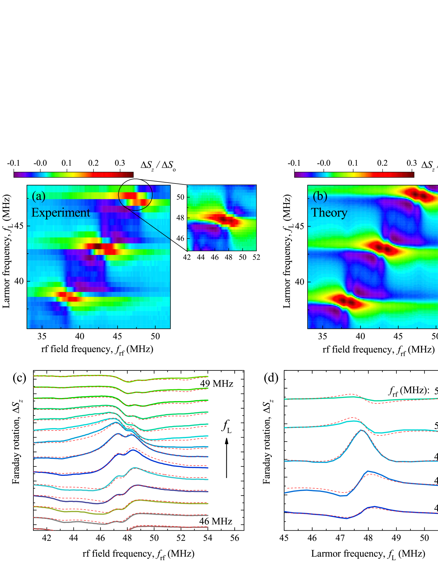
Finally, we show the comprehensive picture of the spin polarization dependence on and for V [Fig. 4(a)]. has pronounced maxima at the ESR-RSA resonances, where . We observe resonances for , , and , remind that MHz. Interestingly, we do not observe any resonance features on the line outside the resonances with . This indicates that the pure ESR on the nonamplified spin polarization is relatively small, while RSA dramatically enhances the ESR effect. Later on we will show that this observation can be treated the other way round as suppression of RSA by the resonant rf field. Another observation that can be made is that the width of the resonance is larger than its height, i.e., . This is also seen in Figs. 4(c) and 4(d) showing the dependences of spin polarization on and , respectively (horizontal and vertical slices of the map in Fig. 4(a) near the resonance). The width of for is determined by the spin dephasing time and, as follows from Fig. 2(a), by the rf field amplitude. On the other hand, the corresponding width seems to be contributed by and independent of the rf field amplitude. In fact, also contributes to the spectral widths for , as it follows from the theory below. The spectra in Fig. 4(c) and Fig. 4(d) show similar derivative-like peculiarity at frequency when or , respectively, is out of resonance with .
IV Theory
The behavior of the total electron spin in an external magnetic field under RSA is described by an inhomogeneous Bloch equation
| (1) |
where is the spin relaxation time at low and is the angular velocity of spin precession, which is the sum of a constant component parallel to the permanent magnetic field , with being the Larmor frequency, and a rotating component orthogonal to , with being the Rabi frequency, , and . Recall that the experimental oscillating rf magnetic field is the sum of two fields rotating in opposite directions with frequency , and the counter-rotating term, i.e., rotating oppositely to , is neglected as Abragam (1961). The inhomogeneous term in Eq. (1) with Dirac delta functions describes repetitive amplification of spin component by successive equidistant laser pulses arriving at times by a quantity per pulse, so that . The term with thermal equilibrium spin is dropped off from Eq. (1) because it is negligible compared to the resulting spin polarization achieved in the experiment under optical pumping.
Between every two adjacent pulses the spin evolves according to the homogeneous Bloch equation, Eq. (1) without the last term. Multiplying this equation scalarly by removes the term and reveals an exponential decay of the absolute spin magnitude, , so it is natural to represent the spin vector in the form of the product
| (2) |
where the vector amplitude satisfies
| (3) |
as one may verify with substituting Eq. (2) in the homogeneous Bloch equation. Equation (3) means that only the orientation of , not its absolute value , changes with time. Thus, by Eq. (2) the spin rotates and simultaneously decays until the next laser pulse arrives, and the rotation is fully determined by the angular velocity .
The current spin orientation is characterized by the unit vector and can be obtained from the initial spin orientation by rotation around a unit axis through an angle , which can be expressed thus:
| (4) |
where
| (5) |
is a quaternion, a special type of hypercomplex numbers particularly effective in various physical problems involving rotations Sob’yanin (2016); Gorham and Laughlin (2019); Kadek et al. (2019); Gubbiotti et al. (2019); Akemann et al. (2019); Faure-Beaulieu and Noiray (2020). A quaternion is the sum of a scalar part and a vector part , and the corresponding conjugate quaternion is . Any vector is a quaternion with zero scalar part; e.g., the spin can be considered as the quaternion . The product of two quaternions and is defined as
| (6) |
and is associative, , but not commutative, . Any quaternion of the form (5) has unit norm, which means that . It follows from Eq. (5) that for any quaternion of unit norm
| (7) |
The knowledge of the time behavior of means the knowledge of the rotational dynamics of the spin. In analogy to the work Belykh et al. (2020b), one can write
| (8) |
where and , with . The vector , where , has absolute value , where is the angular frequency detuning. Equation (8) shows that the current spin orientation is obtained from the initial orientation with superposition of two successive rotations around fixed axes, the first around through angle and the second around through angle . Both rotations are performed in the laboratory frame of reference, but an interpretation invoking the rotating frame of reference is evident: the first rotation corresponds to spin precession with angular velocity in the rotating frame, while the second rotation describes proper rotation with angular velocity of the frame itself, thus giving the spin orientation already in the laboratory frame.
Now we may return to the full dynamics and calculate the observed spin signal. The pump-probe spectroscopy measures the spin (more precisely, its component) and simultaneously amplifies it, but this occurs only at the times of arrival of laser pulses, when the spin changes by . Assuming that the spin measurement occurs just before its amplification, we may relate the spins at two adjacent times of measurement,
| (9) |
where is the quaternion corresponding to spin rotation between the th and th pulses. Equation (9) equally relates and , and , and so on, so repetitively iterating gives the spin at some time of measurement (we arbitrarily choose ),
| (10) |
where
| (11) |
is the quaternion giving rotation starting at the time pulses before and ending at the time of measurement.
Every entering Eq. (11) corresponds to spin rotation from the th to the th pulse and is given by Eq. (8) in which we should put and take as the initial orientation of at time , which is denoted by . The vector rotates around with frequency , which by Eq. (4) is expressed as . Therefore, , where and denotes the th power of a quaternion , the quaternionic product of identical quaternions, . We then have , where by Eq. (7) and , so that
| (12) |
Combining Eqs. (11) and (12) yields , or finally
| (13) |
We see from Eqs. (4) and (13) that describes rotation of , initially oriented along , around through angle and subsequent rotation around through angle .
To find the observed , we should project Eq. (10) on , which can be performed by using Eq. (6) or applying the rotation tensor Wittenburg (2016),
| (14) | |||||
In the experiment, we measure the signal averaged over , more precisely, the difference between the average signal in the absence, , and the presence, , of the rf magnetic field. By transforming the products of trigonometric functions in Eq. (14) to their sums, averaging over , directly summing the resulting series by using the formula Gradshteyn and Ryzhik (2007), and calculating and subtracting , we arrive at the final expression for the observed ESR spectrum under RSA,
| (15) | |||||
V Discussion
Equation (15) provides good fit to the experimental data as shown in Figs. 2(a), 2(b), 4(c), 4(d). The theory also finely reproduces the two-dimensional map [Figs. 4(a), 4(b)]. In the calculations we use ns. By comparing the experiment to the theory, we can relate the Faraday rotation signal measured in the experiment, , to the rf-induced change in the spin polarization, , measured in units of the spin polarization created by the laser pulse, , i.e., we can determine the coefficient in the relation . Similarly, we can determine the coefficient between the rf field amplitude and rf voltage . We use the same coefficients for all the data. In this way the signal in Figs. 2(a), 2(b), 4(a) is shown not in arbitrary units but directly in units of , while the upper scale in Figs. 2(b) and 2(c) shows the values of .
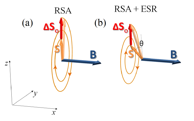
Thus, we observe clear effect of ESR on RSA, and all experimental dependences are well reproduced by the single analytical equation (15) with the same parameters. To understand the effect qualitatively, we refer to the scheme in Fig. 5. In the absence of the rf field [Fig. 5(a)], spin precesses in the plane about magnetic field with frequency , decays with time and is enhanced by with period . For RSA and we can write , so
| (16) |
When the oscillating rf field with frequency is applied to the system, it leads to declination of the spin from the plane by an angle , while the optical pumping drives the spin back toward the plane [Fig. 5(b)]. As a result, the measured component acquires a factor . In the experiment we measure the reduction of the spin polarization for small . These rough estimates explain the unexpected quadratic increase in with observed in Fig. 2(b). This is contrary to the classical ESR case, where is aligned along while the rf field drives it out this direction, and the precessing spin component that is measured in the experiment is proportional to for small .
In this way, the resonant rf field inhibits RSA. Figure 2(a) shows that at the maximal rf voltage corresponding to mT [upper scale in Fig. 2(b)] the maximal inhibition of the spin signal is achieved at and reaches . This means that the rf field almost completely suppresses [see Eq. (16)]. On the other hand, in the color map [Fig. 4(a) and (b)] one can note the negative signal , which means the enhancement of RSA. The minimal is reached slightly out of the RSA resonance and can be interpreted as the tuning of spin precession toward the RSA condition with the rf field. Thus, the rf field not only inhibits spin polarization in the RSA condition but also recovers spin polarization out of RSA. As follows from Fig. 4(a), at V the maximal spin inhibition is about , while the maximal spin recovery is about .
VI Conclusions
We have studied the combined RSA-ESR resonance by pumping and simultaneously probing the electron spin polarization in -GaAs by periodic laser pulses and applying an oscillating rf magnetic field. We have shown that the rf field strongly modifies the optically-created and amplified spin polarization. At small rf field amplitudes, this modification is maximal at the ESR condition and quadratic on the rf field amplitude. At higher rf field amplitudes, the spin polarization shows the double-peaked behavior as a function of the rf field frequency. These observations are unusual when compared to the standard ESR. The rf field can both drive spin precession out of the RSA resonance, thus suppressing spin polarization, or enhance it by tuning spin precession towards the RSA resonance. The experimental results are fully reproduced by a theory considering the electron spin precession in a varied magnetic field under pulsed illumination. This study paves the way for the control and manipulation of the optical spin amplification by the rf or microwave field.
VII Acknowledgments
Acknowledgements.
We are grateful to I. A. Akimov for fruitful discussions. The work was supported by the Russian Science Foundation through grant No. 18-72-10073.References
- Poole (1996) C.P. Poole, Electron Spin Resonance: A Comprehensive Treatise on Experimental Techniques, 2nd ed. (Dover Publications, Mineola, NY, 1996).
- Cavenett (1981) B. C. Cavenett, Optically detected magnetic resonance (O.D.M.R.) investigations of recombination processes in semiconductors, Adv. Phys. 30, 475–538 (1981).
- Hermann and Lampel (1971) C. Hermann and G. Lampel, Measurement of the g Factor of Conduction Electrons by Optical Detection of Spin Resonance in p-Type Semiconductors, Phys. Rev. Lett. 27, 373 (1971).
- Belykh et al. (2020a) V.V. Belykh, D.R. Yakovlev, and M. Bayer, Optical detection of electron spin dynamics driven by fast variations of a magnetic field: a simple method to measure , , and in semiconductors, arXiv:2004.09408 (2020a).
- Meier and Zakharchenya (1984) F. Meier and B. P. Zakharchenya, eds., Optical Orientation (Horth-Holland, Amsterdam, 1984).
- Kikkawa and Awschalom (1998) J. M. Kikkawa and D. D. Awschalom, Resonant Spin Amplification in n-Type GaAs, Phys. Rev. Lett. 80, 4313 (1998).
- Yakovlev and Bayer (2017) D. R. Yakovlev and M. Bayer, Coherent Spin Dynamics of Carriers, in Spin Phys. Semicond., edited by M. I. Dyakonov (Springer International Publishing, Cham, 2017) p. 155.
- Yugova et al. (2009) I. A. Yugova, A. A. Sokolova, D. R. Yakovlev, A. Greilich, D. Reuter, A. D. Wieck, and M. Bayer, Long-Term Hole Spin Memory in the Resonantly Amplified Spin Coherence of InGaAs/GaAs Quantum Well Electrons, Phys. Rev. Lett. 102, 167402 (2009).
- Kugler et al. (2011) M. Kugler, K. Korzekwa, P. Machnikowski, C. Gradl, S. Furthmeier, M. Griesbeck, M. Hirmer, D. Schuh, W. Wegscheider, T. Kuhn, C. Schüller, and T. Korn, Decoherence-assisted initialization of a resident hole spin polarization in a p-doped semiconductor quantum well, Phys. Rev. B 84, 085327 (2011).
- Griesbeck et al. (2012) M. Griesbeck, M. M. Glazov, E. Ya. Sherman, D. Schuh, W. Wegscheider, C. Schüller, and T. Korn, Strongly anisotropic spin relaxation revealed by resonant spin amplification in (110) GaAs quantum wells, Phys. Rev. B 85, 085313 (2012).
- Hernandez et al. (2014) F. G. G. Hernandez, G. M. Gusev, and A. K. Bakarov, Resonant optical control of the electrically induced spin polarization by periodic excitation, Phys. Rev. B 90, 041302(R) (2014).
- Macmahon et al. (2019) Michael Macmahon, Joseph R. Iafrate, Michael J. Dominguez, and Vanessa Sih, Observation of magnetic field sweep direction dependent dynamic nuclear polarization under periodic optical electron spin pumping, Phys. Rev. B 99, 075201 (2019).
- Schering et al. (2019) Philipp Schering, Götz S. Uhrig, and Dmitry S. Smirnov, Spin inertia and polarization recovery in quantum dots: Role of pumping strength and resonant spin amplification, Phys. Rev. Research 1, 033189 (2019).
- Saeed et al. (2018) F. Saeed, M. Kuhnert, I. A. Akimov, V. L. Korenev, G. Karczewski, M. Wiater, T. Wojtowicz, A. Ali, A. S. Bhatti, D. R. Yakovlev, and M. Bayer, Single-beam optical measurement of spin dynamics in CdTe/(Cd,Mg)Te quantum wells, Phys. Rev. B 98, 075308 (2018).
- Kotur et al. (2018) M. Kotur, F. Saeed, R. W. Mocek, V. L. Korenev, I. A. Akimov, A. S. Bhatti, D. R. Yakovlev, D. Suter, and M. Bayer, Single-beam resonant spin amplification of electrons interacting with nuclei in a GaAs/(Al,Ga)As quantum well, Phys. Rev. B 98, 205304 (2018).
- Belykh et al. (2016) V. V. Belykh, E. Evers, D. R. Yakovlev, F. Fobbe, A. Greilich, and M. Bayer, Extended pump-probe Faraday rotation spectroscopy of the submicrosecond electron spin dynamics in n-type GaAs, Phys. Rev. B 94, 241202(R) (2016).
- Belykh et al. (2019) V. V. Belykh, D. R. Yakovlev, and M. Bayer, Radiofrequency driving of coherent electron spin dynamics in n-GaAs detected by Faraday rotation, Phys. Rev. B 99, 161205(R) (2019).
- Rabi (1937) I. I. Rabi, Space Quantization in a Gyrating Magnetic Field, Phys. Rev. 51, 652 (1937).
- Crooker et al. (2009) Scott A. Crooker, Lili Cheng, and Darryl L. Smith, Spin noise of conduction electrons in n-type bulk GaAs, Phys. Rev. B 79, 35208 (2009).
- Petrov et al. (2018) M. Yu. Petrov, A. N. Kamenskii, V. S. Zapasskii, M. Bayer, and A. Greilich, Increased sensitivity of spin noise spectroscopy using homodyne detection in n-doped GaAs, Phys. Rev. B 97, 125202 (2018).
- Abragam (1961) A. Abragam, Principles of Nuclear Magnetism (Clarendon Press, 1961).
- Sob’yanin (2016) D. N. Sob’yanin, Breakdown of the Goldreich–Julian relation in a neutron star, Astron. Lett. 42, 745 (2016).
- Gorham and Laughlin (2019) Caroline S. Gorham and David E. Laughlin, Crystallization in three dimensions: Defect-driven topological ordering and the role of geometrical frustration, Phys. Rev. B 99, 144106 (2019).
- Kadek et al. (2019) Marius Kadek, Michal Repisky, and Kenneth Ruud, All-electron fully relativistic Kohn-Sham theory for solids based on the Dirac-Coulomb Hamiltonian and Gaussian-type functions, Phys. Rev. B 99, 205103 (2019).
- Gubbiotti et al. (2019) Alberto Gubbiotti, Mauro Chinappi, and Carlo Massimo Casciola, Confinement effects on the dynamics of a rigid particle in a nanochannel, Phys. Rev. E 100, 053307 (2019).
- Akemann et al. (2019) Gernot Akemann, Mario Kieburg, Adam Mielke, and Tomaž Prosen, Universal Signature from Integrability to Chaos in Dissipative Open Quantum Systems, Phys. Rev. Lett. 123, 254101 (2019).
- Faure-Beaulieu and Noiray (2020) Abel Faure-Beaulieu and Nicolas Noiray, Symmetry breaking of azimuthal waves: Slow-flow dynamics on the Bloch sphere, Phys. Rev. Fluids 5, 023201 (2020).
- Belykh et al. (2020b) V. V. Belykh, M. V. Kochiev, D. N. Sob’yanin, D. R. Yakovlev, and M. Bayer, Anomalous magnetic suppression of spin relaxation in a two-dimensional electron gas in a GaAs/AlGaAs quantum well, Phys. Rev. B 101, 235307 (2020b).
- Wittenburg (2016) J. Wittenburg, Kinematics: Theory and Applications (Springer, Berlin, 2016).
- Gradshteyn and Ryzhik (2007) I. S. Gradshteyn and I. M. Ryzhik, Table of Integrals, Series, and Products, 7th ed. (Academic, Amsterdam, 2007).