Geometric Pressure Minimisation of a Theoretical Die for Ceramic Extrusion
Abstract
As manufacture processes become more complex, the direct extrusion of material still remains a reliable method of fabrication and processing a variety of materials, but most commonly ceramics. These materials are shaped by a die that can determines the output shape of the material. A generic complex die design was used to explore how varying the geometry of the die can affect the overall and component pressures felt during the extrusion process, based on a Benbow-Bridgwater model. From this we determined some general interactions and relationships, comparing how varying geometries can lead to extrusions of the same shape, and discuss how to balance this against desired effects that the extrusion process may have on the material.
1 Introduction
Ceramic extrusion is a common processing technique, useful in the production of objects with regular cross-sectional areas and usually the source of building materials such as tiles or bricks [1]. Due to plastic-like quality of the clay-water mix, ceramics can easily be cold-formed and therefore extrusion has allowed for a simple and achievable route for ceramic formation for decades.
Alongside this, the simplicity of the extrusion process allows for a wide-range of clay formulations, with or without additives, to be utilised. But in general, ceramics are characterised by low thermal and electrical conductivity and high melting temperature. All of these properties are determined entirely by the microstructural mix and can be varied to affect the porosity, mechanical strength and overall shape of the final product.
The extrusion of ceramic materials can be mathematically described using the Benbow model, that relies on both materials properties and the geometry of the extrusion die to describe the pressure drops felt across the die [2]. This was then expanded to include more complex geometries and multi-component dies [3]. With more current manufacturing capabilities, we can instead begin to imagine more complex and optimal die designs that minimise the overall pressure felt on across the die [4, 5]. We use a generic complex die design, such as those in Ref. [6], in order to try and make general statements about design choices that should result in this minimum pressure geometry.
2 Benbow-Bridgwater Model
The extrusion of ceramic pastes can be modelled using the Benbow-Bridgwater model and describes the extrusion pressure as a function of the material properties and the geometrical description of the die. Such a model can be most simply described in a die with a circular cross section with a square entry feed as [2, 7, 8]
| (1) |
Here and are terms that represent flow properties, and are generic material dependent terms and and are the bulk yield and wall shear felt by the material. and are diameters of the barrel and die, is the die-land length. Finally, the pressure variations are driven by the extrudate velocity .
More complex geometries of die can instead be described by an extension of the above that takes into account the geometry change at each point. The pressure therefore is an additive combination of the pressure drops across each section of the die, with form [6, 9, 10, 11, 12]
| (2) |
is the diameter of each portion, is the number of internal holes with diameter , is the volumetric flow rate, and are the area and die-land length at a location and is the angle of the die-entry (located solely in the term). We use the material example of red clay from Ref. [6], providing the material dependent parameters (, , , , , ). The layout can be seen in Fig. 1, with all the geometrical terms above included, and an example of the individual and total contribution to the pressure across the die can be seen in Fig. 2.
Due to the additive nature of these pressure drops, we can begin this analysis simply by separating the die into smaller sections and noting how differing geometries affect the pressure values. The only fixed terms are the geometry of both the opening () and exit (both and ) of the die, such that all variations result in the same extruded ceramic shape. It may be that large variations in the opening and exit dimensions may result in a shift of the minimum pressure die geometry, however initial tests suggest that the dependencies described in the following sections hold for at least small variations ( 10%) of these values.
3 - Angular Constrictive Section
The region belongs to the constrictive section of the die, defined by both an angle of constriction and a length . It is driven purely by:
| (3) |
Varying purely the angle here produces the data seen in Fig. 3. It can be seen from this data that an inflexion point lies at and any angle larger than this is roughly equally preferable when it comes to minimising the pressure felt on the die. This variation can also be thought of as minimising the distance between the barrel and the final extrusion - low angles would provide extremely large distance, with the pressure being asymptotic to .
This can be somewhat misleading - the equation does not depend explicitly on the length the die section. As such, variations in the angle have a direct impact on the length and this is not explicitly reflected in the equation. We denote that length has form
| (4) |
We instead wish to explore how the pressure varies with the exit diameter and the angle , highlighting regions of equal die-length. Fig. 4 shows this data, displaying both the regions of equal pressure felt by the die and regions of equal die length. A combination of these two viewpoints is required in order to minimise the pressure felt, whilst restricting unfeasible cases such as extremely long die lengths or extremely high pressure layouts.
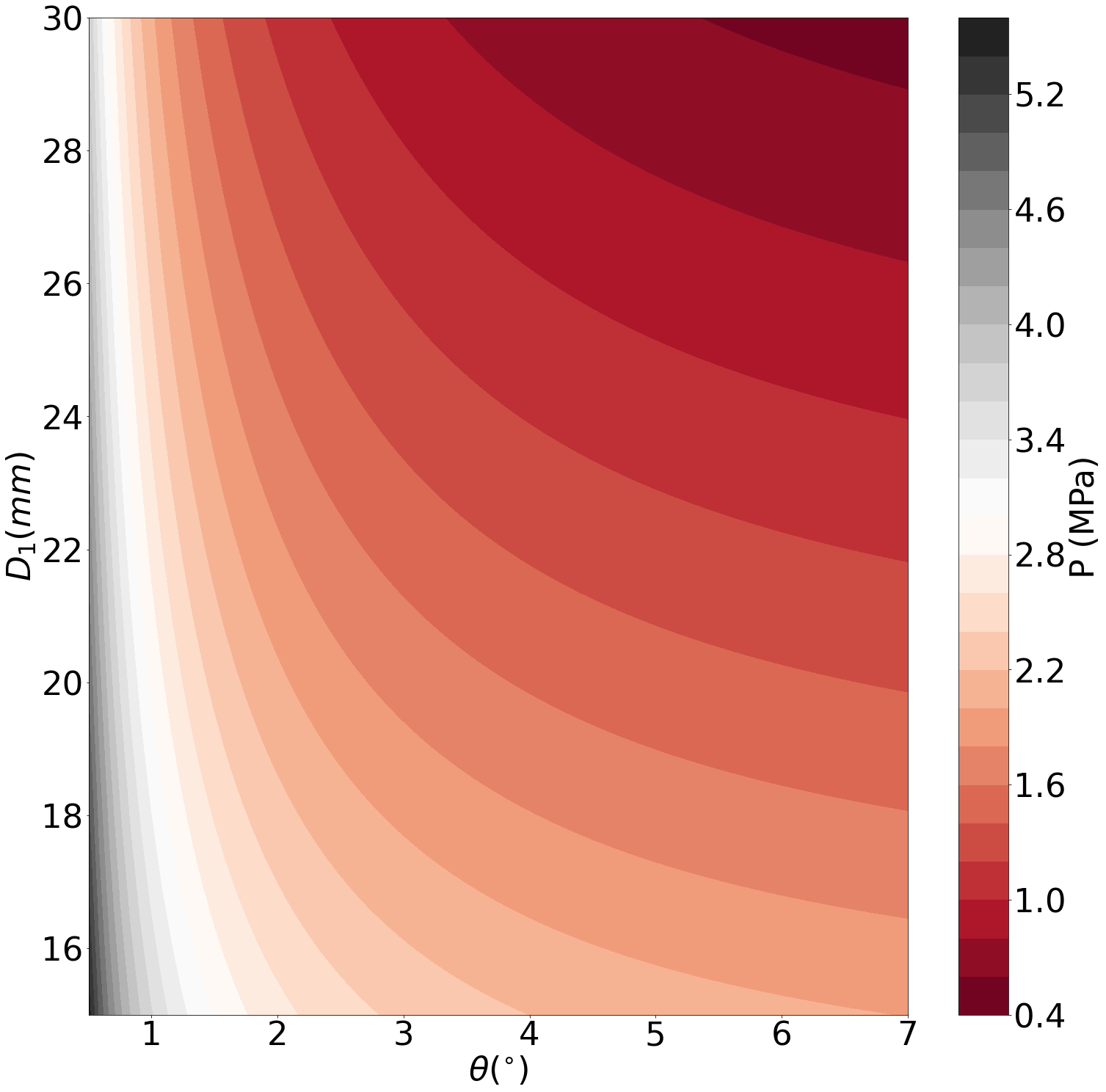
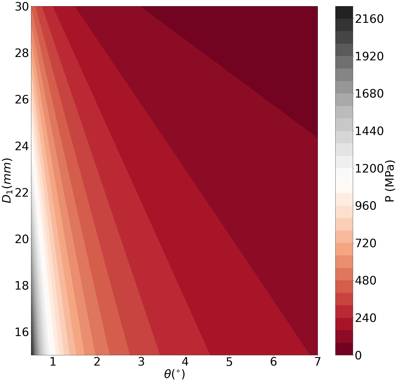
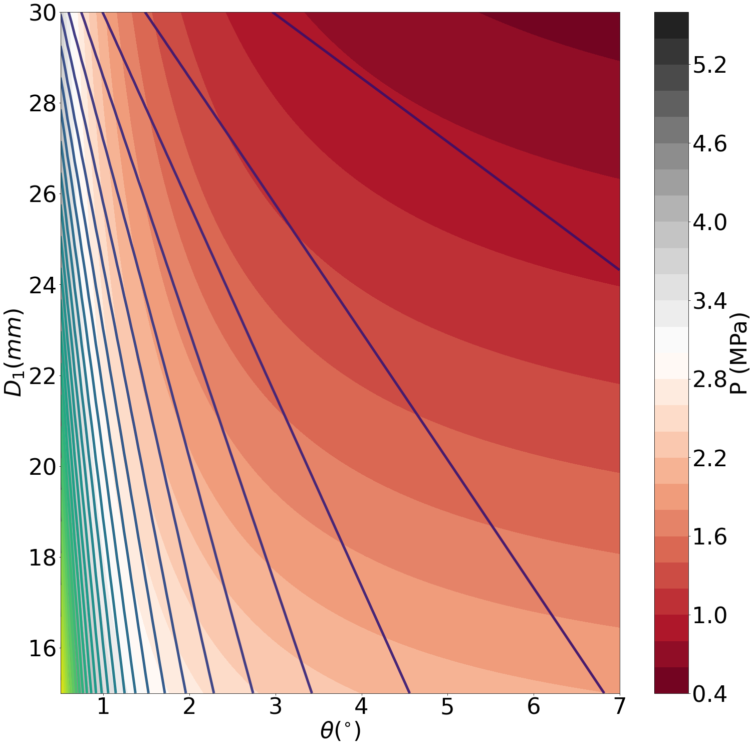
If we overlap these two data sets, we can now produce a figure that allows us the pick the minimum pressure combination of and , having chosen the length of the desired die. Fig. 4 shows this result - indicating regions of geometrical and pressure induced infeasibility. In other words, at large angle and large exit diameter , the die component length tends toward zero, and at shallow angles and small exit diameter, the die component length tends towards extremely long die-lengths. It also allows us to state the the minimum pressure setup for a chosen die length, angle or exit diameter. For instance, a die with length mm, the minimum pressure geometry is roughly in the region of and mm. There is a region of similar pressure solutions around this point, any of which would provide an ample die geometry to minimise the pressure.
4 - Connector with Internal Holes
The following portion is mathematically described by the terms and - denoting a connector with a series of internal holes that feed to the final portion of the die. This has form
| (5) |
Here the pressure is directly dependent on the material properties, the die geometry and , the volumetric flow rate.
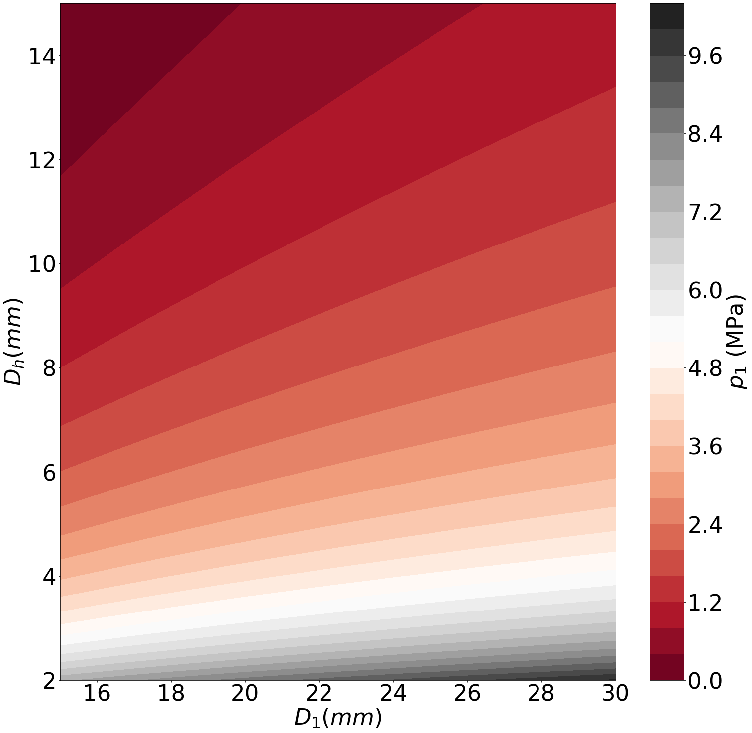
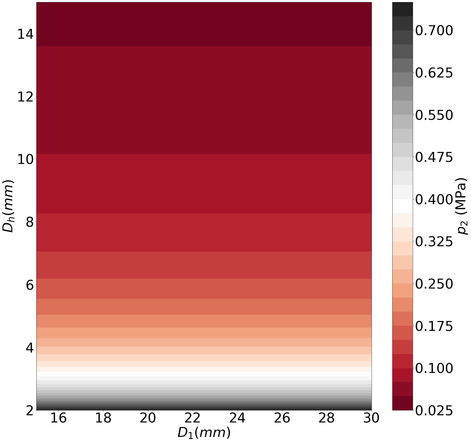
Within this region, using the material parameters for red clay in Ref. [6], is usually much larger than . Fig. 5 for instance shows immediately this difference and how often . It also displays how the most obvious geometric terms , diameter of the internal holes, and , diameter of the connector between this and the prior section, have a very different effect on the pressure with the former having a profound difference in pressure, while the latter has very little. As such, we can instead state that the more consequential pressure component here is the internal holes in the die.
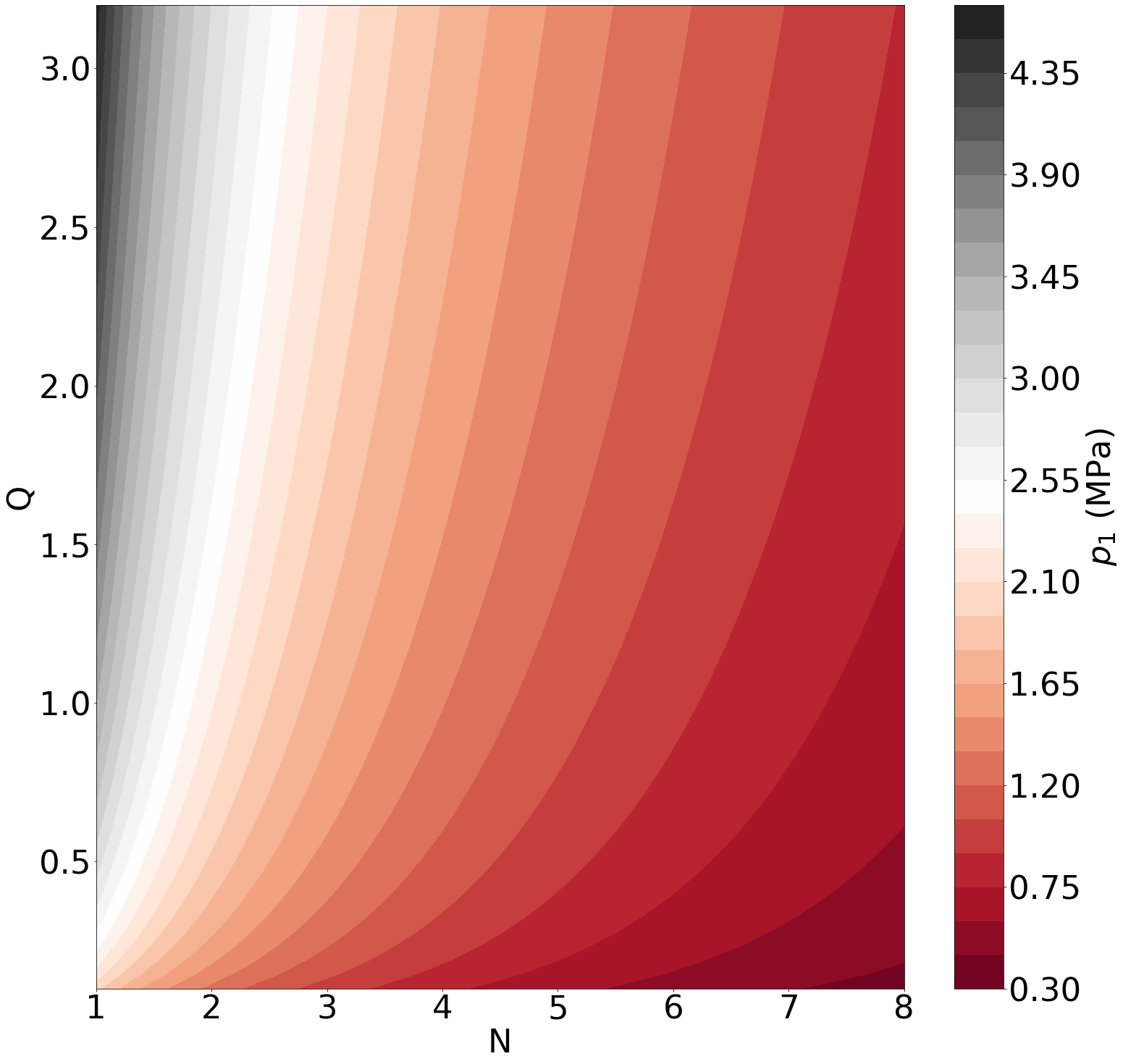
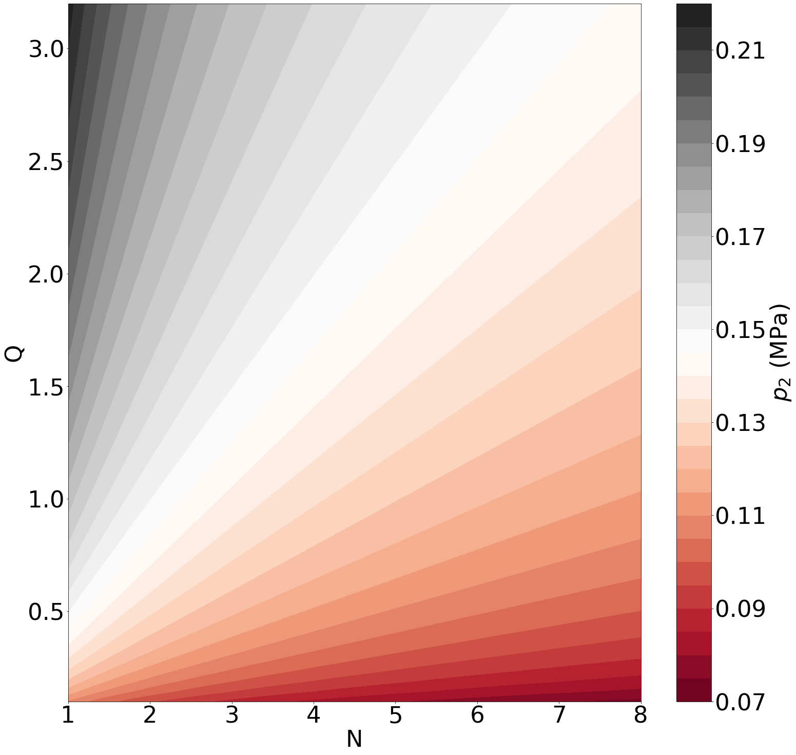
Fig. 6 shows the pressure variation with volumetric flow rate and number of internal holes . As expected, a higher flow rate tends to induce a larger pressure, again with . Also intuitively, an increased number of holes tends to ensured a reduced pressure. These dependencies are more linear for than , as can be seen from the form of the equations above, however they both highlight how maximising the size of the opening will minimise the pressure.
This does however highlight one obvious drawback with this method - that it makes no prediction of how the die geometry has an effect on the final extruded material. In certain materials, the extrusion process can have a direct impact on the alignment of the microstructure [13, 14, 15, 16, 17, 18] or, in more general cases, cause agglomerate breakdown of ceramic components and agglomeration of defects such as air bubbles [19, 20]. The exact purpose that the internal holed structure has may depend on the type of material wanted for extrusion and therefore you easily consider any layout an acceptable pressure loss. However, this also means we can identify regions of similar pressure loss and then choose from those, based on the limitations of our die manufacture.
5 - Stepped Constrictive Section
The final portion of the die design involves three stepped lengths, characterised by three diameters and three lengths. These have form
| (6) |
where and are the length and area of their respective sections and and are the outer and inner diameter of the desired extrusion geometry.
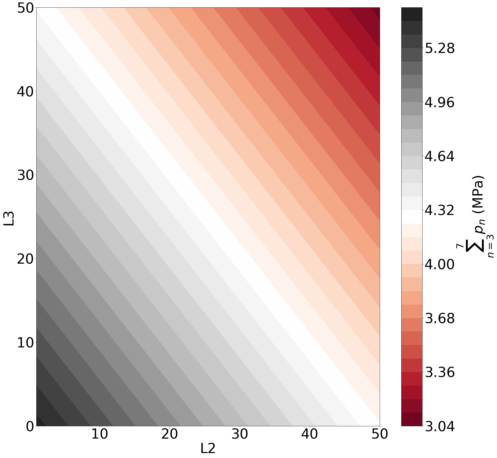
We begin by varying the lengths of the three constituent steps, , setting the total length of the section to 120 mm. Fig. 7 shows the pressure relation, constraining the total length through . Intuitively, pressure is minimised by increasing the overall average of the diameter of the stepped section, achieved by maximising the lengths of and over . Again, this may have adverse effects on the material properties of the extrusion, however this does suggest that similar dimensions of extrusion could be achieved for a much lower pressure. Similar relationships exist for the diameters of the constituent sections, suggesting the pressure can be minimised by maximising the total internal area that still produces the same extrusion shape.
6 General Results
Using a generic complex die design, we have explored how varying the geometry of the die can affect the pressure in multiple ways, in differing types of die component. Some broad facts emerge, including:
-
•
For constrictive angled die sections, the optimum angle varies depending on the length and opening/exit diameter. However, angles in the region of 3 - 5∘ can in general be a safe choice.
-
•
For connectors with internal holes, intuitively the larger the area of entry and the number of entry holes, the lower the pressure. However, this must be matched carefully against the desired effect on the material being fed through connector.
-
•
For long, stepped die-land sections, the pressure is minimised by keeping the ceramic in largest sections for as long as possible and by minimising the total length of this component. Again, this is very intuitive but must be matched against the need to affect the material being extruded in this way. Whether this section could be replaced with another angled component and still produce the same material properties is currently unknown.
Using this knowledge, we can envisage how custom die-design could result in more bespoke and complex effects on the extruded material, all whilst minimising the overall pressure and wear on such a custom die. In addition, as direct extrusion becomes a method of fabrication for materials beyond ceramics [4, 21] and more complex die designs become more feasible and accessible, we can also begin to expect material specific die designs.
7 Conclusion
A generic complex die was used to probe how varying geometries can affect the overall pressure felt during the extrusion process. From this we determined some general interactions and relationships, primarily how to achieve similar shape outputs in a shorter die. However these do not take into account the effect that the extrusion process has the material itself. This will vary depending on the desired effect and the material chosen, however this does point toward a counterbalancing term that will need to be taken into account for a complete, material specific die design.
References
- [1] Händle, F. (Ed.). (2007). Extrusion in ceramics. Springer Science & Business Media.
- [2] Benbow, J. J., Lawson, T. A., Oxley, E. W., & Bridgwater, J. (1989). Prediction of past extrusion pressure. American Ceramic Society Bulletin, 68(10), 1821-1824.
- [3] Benbow, J. J., Jazayeri, S. H., & Bridgwater, J. (1991). The flow of pastes through dies of complicated geometry. Powder technology, 65(1-3), 393-401.
- [4] Hölker, R., & Tekkaya, A. E. (2016). Advancements in the manufacturing of dies for hot aluminum extrusion with conformal cooling channels. The International Journal of Advanced Manufacturing Technology, 83(5-8), 1209-1220.
- [5] Oter, Z. C., Coskun, M., Akca, Y., Sürmen, Ö., Yılmaz, M. S., Özer, G., Tarakçı, G & Koc, E. (2019). Benefits of laser beam based additive manufacturing in die production. Optik, 176, 175-184.
- [6] Vitorino, N., Freitas, C., Ribeiro, M. J., Abrantes, J. C. C., & Frade, J. R. (2015). Porous hollow tubes processed by extrusion of ceramic emulsions. Applied Clay Science, 105, 60-65.
- [7] Horrobin, D. J., & Nedderman, R. M. (1998). Die entry pressure drops in paste extrusion. Chemical Engineering Science, 53(18), 3215-3225.
- [8] Wells, L. J., Nightingale, S. A., & Spinks, G. M. (2005). The effect of temperature on the extrusion behavior of a polymer/ceramic refractory paste. Journal of materials science, 40(2), 315-321.
- [9] Raupp-Pereira, F., Ribeiro, M. J., Segadaes, A. M., & Labrincha, J. A. (2007). Extrusion and property characterisation of waste-based ceramic formulations. Journal of the European Ceramic Society, 27(5), 2333-2340.
- [10] Vitorino, N., Ribeiro, M. J., Abrantes, J. C. C., Labrincha, J. A., & Frade, J. R. (2014). Extrusion of ceramic pastes: An alternative approach to obtain the Benbow’s model parameters. Ceramics International, 40(9), 14543-14547.
- [11] Ribeiro, M. J., Blackburn, S., Ferreira, J. M., & Labrincha, J. A. (2006). Extrusion of alumina and cordierite-based tubes containing Al-rich anodising sludge. Journal of the European Ceramic Society, 26(4-5), 817-823.
- [12] Guilherme, P., Ribeiro, M. J., & Labrincha, J. A. (2009). Behaviour of different industrial ceramic pastes in extrusion process. Advances in Applied Ceramics, 108(6), 347-351.
- [13] Peigney, A., Flahaut, E., Laurent, C., Chastel, F., & Rousset, A. (2002). Aligned carbon nanotubes in ceramic-matrix nanocomposites prepared by high-temperature extrusion. Chemical Physics Letters, 352(1-2), 20-25.
- [14] O’Neill, R. E., Royer, J. R., & Poon, W. C. (2019). Liquid migration in shear thickening suspensions flowing through constrictions. Physical review letters, 123(12), 128002.
- [15] Xu, Q., Singh, A., & Jaeger, H. M. (2020). Stress fluctuations and shear thickening in dense granular suspensions. Journal of Rheology, 64(2), 321-328.
- [16] Freitas, C., Vitorino, N., Ribeiro, M. J., Abrantes, J. C. C., & Frade, J. R. (2015). Extrusion of ceramic emulsions: Preparation and characterization of cellular ceramics. Applied Clay Science, 109, 15-21.
- [17] Böhm, H., & Blackburn, S. (1994). Agglomerate breakdown in fine alumina powder by multiple extrusion. Journal of materials science, 29(22), 5779-5786.
- [18] Kocserha, I., & Kristály, F. (2010). Effects of Extruder Head’s Geometry on the Properties of Extruded Ceramic Products. In Materials Science Forum (Vol. 659, pp. 499-504).
- [19] Wildman, R. D., & Blackburn, S. (1998). Breakdown of agglomerates in ideal pastes during extrusion. Journal of materials science, 33(21), 5119-5124.
- [20] Mason, M. S., Huang, T., Landers, R. G., Leu, M. C., & Hilmas, G. E. (2009). Aqueous-based extrusion of high solids loading ceramic pastes: Process modeling and control. Journal of materials processing technology, 209(6), 2946-2957.
- [21] Mohammed, M. A. P., Wanigasooriya, L., Chakrabarti-Bell, S., & Charalambides, M. N. (2017). Extrusion of unleavened bread dough: Experiments and simulations. Journal of Rheology, 61(1), 49-65.