revtex4-1Repair the float
Vacuum Characterization of a Compact Room-temperature Trapped Ion System
Abstract
We present the design and vacuum performance of a compact room-temperature trapped ion system for quantum computing, consisting of a ultra-high vacuum (UHV) package, a micro-fabricated surface trap and a small form-factor ion pump. The system is designed to maximize mechanical stability and robustness by minimizing the system size and weight. The internal volume of the UHV package is only , a significant reduction in comparison with conventional vacuum chambers used in trapped ion experiments. We demonstrate trapping of 174Yb+ ions in this system and characterize the vacuum level in the UHV package by monitoring both the rates of ion hopping in a double-well potential and ion chain reordering events. The calculated pressure in this vacuum package is , which is sufficient for the majority of current trapped ion experiments.
Systems using atomic ions are among the leading physical platforms for a practical quantum computer because of their long coherence times [1, 2], full connectivity between qubits [3, 4, 5] and high-fidelity gate operations [6, 7, 5]. However, unlike qubits based on solid state devices, the integration approach for scaling trapped ion systems is not obvious. Many ideas for engineering complex trapped ion systems have been outlined to build practically useful trapped ion quantum computing systems [7, 8, 9, 10].
Trapped ion experiments, whether they use traditional linear Paul Traps [11] or micro-fabricated surface traps [12], ultimately rely on a lack of collision events with background gas molecules in order to perform reliable high-fidelity gates. Critically, pressures in the ultra-high vacuum (UHV) regime () are required to keep the background gas collision rates low enough to minimize ion chain reordering events and loss of ions from the trap [8]. Additionally, quantum computation requires high fidelity gates, necessitating excellent opto-mechanical robustness and stability of a scalable trapped ion quantum computer. Optical frequencies of lasers driving near-resonant processes should be stabilized to a part in range in order to properly utilize these transitions for qubit manipulation and read-out [13]. Quantum logic gates are often driven using Raman transition, where two far-detuned non-co-propagating beams with precise frequency difference intersect at the location of the ion. Beam path length and pointing fluctuations of these Raman beams lead to optical phase and intensity fluctuations at the ions, which results in imperfect gates. In order to avoid these problems, the trapped ions system and the optical elements used for the delivery of the laser beams should be stable against environment noise such as temperature fluctuations, air currents and mechanical vibrations. To address these requirements for a scalable trapped ion quantum computer, cryogenic systems were proposed and investigated [8, 14, 15], where the volume of the ultra-high vacuum (UHV) operating area can be minimized by taking advantage of cryogenic temperature while maintaining its vacuum quality. However, there are drawbacks of using cryogenic system, such as the size and cost of a cryogenic system and the vibrations generated by closed cycle cryostats.
In this paper we present a compact trapped ion system operating at room temperature. The system volume is reduced by several orders of magnitude below comparable ion trap systems, while the pressure is maintained in the UHV regime despite the high surface-area-to-volume ratio, making it a suitable system to extend to cryo environments. We present the detailed design of this compact room temperature system, and characterize the vacuum level of the system by measuring the well-to-well hopping rates of trapped 174Yb+ ions in a double-well potential, as well as the occurrence rate of chain re-ordering collisions. The method and results of this vacuum characterization are presented in the end of this article.
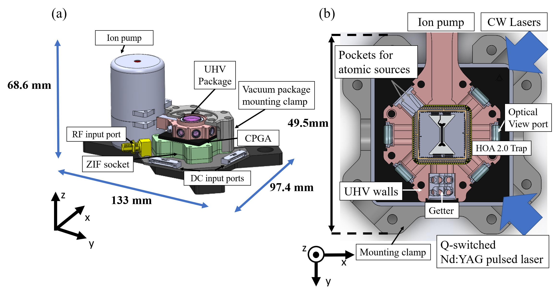
The compact vacuum package is described schematically in Fig. 1(a). A significant reduction in system volume is enabled by two improvements: 1) The ceramic pin grid array (CPGA, NKT CPG10039) which typically acts as an in-vacuum break-out board now is Au-Sn soldered to the ring flame of the package and acts as the electrical feedthrough between UHV and atmosphere; 2) Conflat flanges which typically provide viewports and electrical feedthroughs for additional components have been replaced with laser welded components with significantly reduced size. The vacuum system consists of the UHV package, the atomic source assembly, viewports, the CPGA, the ion pump, and the direct current (DC) and radio frequency (RF) feedthrough connectors, with an overall dimension of . The UHV volume inside the package is . The viewports, non-evaporable getter plug, and atomic source assembly are all welded to the vacuum housing using identical form-factor seals, making them interchangeable for flexibility during system design. Once the trap is die-attached and wire bonded in the CPGA, it is loaded to a UHV packaging facility. The UHV package (ColdQuanta P/N: CQARO-0100.1) is assembled with viewports, non-evaporable getter plug, atomic source, and custom-developed ion pump, and welded for hermeticity. The CPGA ringframe is bonded to the UHV housing by ColdQuanta using a proprietary bonding and alignment procedure. The UHV packaging station operates at vacuum levels, and supports self-aligned assembly with tolerances well within the requirements needed for the optical alignment of the beams in the experiment ( ). Once sealed, the UHV package is removed from the assembly chamber and the ion pump is turned on to maintain the internal vacuum level to .
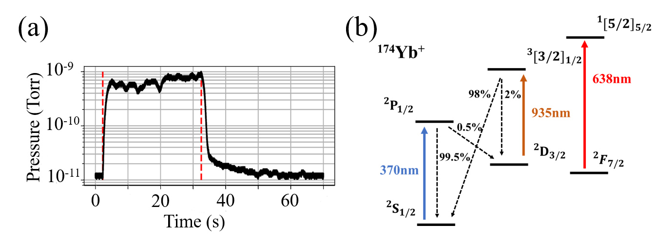
A schematic diagram of the UHV package is shown in Fig. 1(b). The internal volume of the UHV package contains two small pockets, located approximately from the center of the main chamber. Each of the pockets is loaded with a pellet of 99.9 purity metallic Yb with a dimension of diameter and length. We generate neutral Yb flux by focusing a Q-switched Nd:YAG pulsed laser onto the Yb source pellet[16] with an incident beam waist of . The maximum pulse energy used in this experiment is , with a temporal pulse length of . The graph in Fig. 2(a) shows the time-dependence of the pressure inside the UHV package during a ablation loading window as estimated from the ion pump current. The pressure increase during the ablation window demonstrates that the ablation laser removes material from the Yb pellet, and the ion pump current returns to baseline within seconds after the ablation laser is turned off.
A micro-fabricated surface trap (Sandia National Laboratories HOA 2.0 [17]) is mounted in the center of the main chamber in the UHV package. The trap creates a quasi-static potential by a combination of DC and RF electric fields[18]. The neutral atomic flux generated by the ablation laser crosses the trap axis in the center of the trap. Here, the atoms are photoionized by and laser beams via a two-photon process. Ions with sufficiently low kinetic energy are subsequently trapped by the quasi-static potential created by the voltage on the surface trap’s RF and DC electrodes.
The relevant energy diagram of a 174Yb+ ion is shown in Fig. 2(b). The ions are Doppler cooled using the 2SP1/2 transition. Optical re-pumping from the meta-stable 2D3/2 state back to the Doppler cooling cycle is done by a repump laser. A second repump laser at is also applied to remove ions from the meta-stable 2F7/2 state. The CW lasers all co-propagate in the same photonic crystal fiber and are focused onto the ions by a parabolic mirror. The emitted photons from resonant scattering at are collected by an imaging lens with a large numerical aperture (). An electron multiplying CCD (EMCCD) camera (Andor iXon Ultra 888) detects these collected photons to image the trapped ions.
The quality of the vacuum in a trapped ion system dictates the lifetimes of the ion chain. The elastic collision rate between the residual background gas molecules and the trapped ions is a critical parameter of a trapped ion-based quantum computer, since the these collisions with sufficient kinetic energy transfer can significantly disrupt the trapped ion chain. To reliably maintain a chain of ions over the periods of time required for quantum computation, the level of vacuum must be in the UHV regime ()[19].
The ion-molecule interaction is modeled by the electric field of the trapped ion polarizing the electron distribution of a background gas molecule to create an induced dipole moment[14, 20]. This dipole experiences a net attractive force from the ion, and will collide with the ion provided its trajectory passes sufficiently close to the ion. The ion-molecule interaction potential is
| (1) |
where , is the net charge of the ion, is the polarizability of the background molecule, and is the vacuum permittivity. The collision energy in the center-of-mass frame is given by , where is the reduced mass, and are the mass of the ion and the molecule, respectively, and is the relative velocity between the ion and molecule. The critical impact parameter of ion-molecule collision is then given by [21, 22]. The Lagrangian equations of motion result in a radial equation governed by the effective potential where is the angular momentum of the system. When the collision energy is large enough to overcome the barrier between the attractive region (small ) and the repulsive centrifugal region (large ), a short-range collision occurs. The Langevin cross-section of this collision process is given by[23]
| (2) |
Considering the situation where the ion collides with background molecules of density , the rate of ion-molecule collision in close range is denoted as , where the density of the background gas can be expected to obey the ideal gas law at the low densities expected under UHV conditions. Here, is the Boltzmann constant, and and are the background gas pressure and temperature, respectively. The collision rate is then related to the background pressure by
| (3) |
To determine the energy transferred from the molecule to the ion during the elastic collision we calculate the velocity of the ion after the collision as
| (4) |
where is the scattering angle and is the unit vector pointing in the direction perpendicular to the initial velocity vector . On average, the ion’s energy after the collision is
| (5) |
where the brackets indicate an average over , and is the initial kinetic energy of the molecule. We consider the case of a 174Yb+ colliding with a background H2 molecule, which is the dominant remaining constituent in a well-treated vacuum package, at room temperature. An estimated energy transfer averaged over the molecule’s Boltzmann distribution is .
In the previous works, the vacuum pressure of trapped ion systems has been estimated by monitoring the rate of elastic collision between ions and background gas leading to reordering of the position of ions. Here, following the method described in the article[14, 20], we conduct two experiments to characterize the vacuum level of the compact UHV chamber. First, we measure the rate at which an ion trapped in a double-well potential hops from one well to the other, and use Eq. 3 to relate this hopping rate to the background pressure. Second, we monitor the rate of reordering events in an ion chain containing Yb ions of two different isotopes.
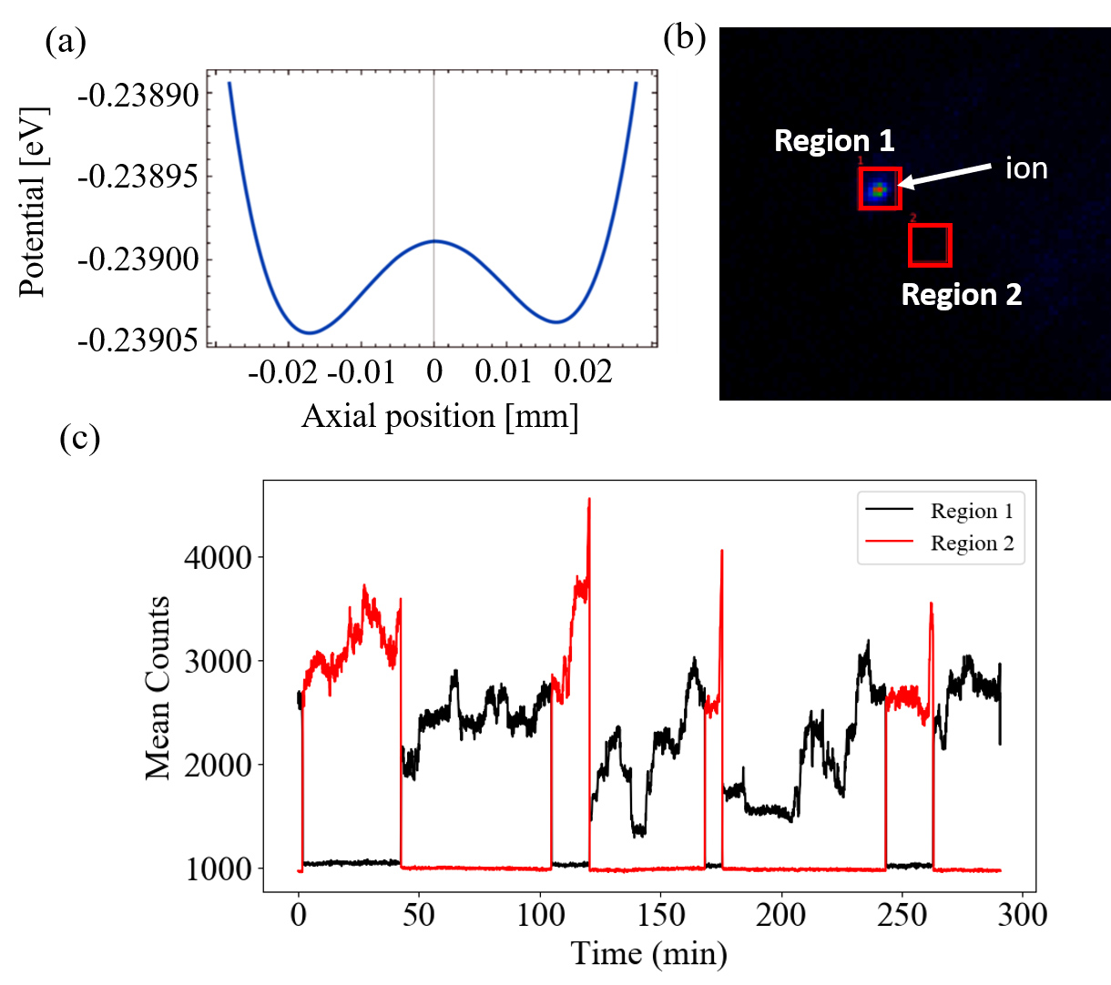
The double-well potential is implemented such that the ion can hop between the two potential minima for nearly all collision events with background molecules. To achieve this condition, the height of the potential barrier between the two minima has to be much lower than the average energy transfer due to a collision event. We set the potential barrier height to , about 17 times lower than the average collision energy . The potential barrier is designed by the trap simulation code provided by Sandia National Laboratories and the simulated DC potential along the axial axis is shown in Fig. 3 (a). The potential barrier height was verified by applying a DC voltage to tilt the axial potential until the ion slides from one well to the other. Under these conditions, we expect every collision event to randomize the ion location after the collision.
The hopping rate in the double-well potential is measured by imaging the ion location on the EMCCD camera to determine which of the two wells contains the ion, as shown in Fig. 3 (b). The mean time between hopping events, which can be extracted from time traces similar to the one shown in Fig. 3(c), is 1 event per 32 7.9 minutes. The actual collision rate is expected to be double the measured hopping rate, since the ion will eventually get Doppler cooled into either well after the collision, and events where the ion settles back into the original well are not detected using our measurement scheme. Thus, substituting , , and into Eq. (3), we obtain the estimated pressure at the ion location as . This vacuum level is comparable to a well-prepared conventional UHV chamber.
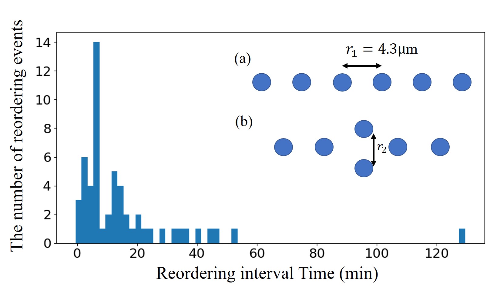
Another method to estimate the pressure is by measuring the rate of reordering events in an ion chain. To estimate the collision energy required to observe a reordering event in a 6-ion chain, we calculate the energy difference between two different chain configurations: one where the ions are aligned along the trap axis in their typical configuration, and the other where two of the ions have been pushed into one of the transverse axis, as shown in the inset of Fig. 4.
When identical ions are stationary in the trap, the total energy of the chain is given by
| (6) |
where is the mass of the ions, are the trap frequencies in the , , and directions, respectively, is the equilibrium position of the -th ion in the trap and is the charge of the ions. Using our experimental parameter (, ), we obtain an energy difference between these two configuration to be about . Therefore, if the ion chain gained an energy in excess of about from a collision event, a reordering event can occur. Comparing this potential difference to the average energy transferred to an ion in a collision, we expect about 25 of collisions to transfer sufficient energy to the chain for reordering to occur.
To measure the rate of re-ordering events, we trap a chain of 6 ions containing two different isotopes of Yb: four 174Yb+ ions and two 172Yb+ ions. The small difference in mass should not significantly change the expected energy barrier of . Due to the isotope shift, only one of the isotopes will be resonant with the Doppler cooling laser, and therefore be visible on the EMCCD camera. In this experiment, we choose the four 174Yb+ as the bright ions while the 172Yb+ ions remain dark.
A histogram showing the time interval between ion reordering events is shown in Fig. 4. We record a video of the ion chain configuration under constant Doppler cooling for a continuous 15 hour period during which we observe 54 reordering events. The width of each time bin is . The observed average reordering rate is one event per 16 2.7 minutes. For 33 out of 54 reordering event only one of the two dark ions moved positions, while for the remaining events both of the dark ions are seen to move. A chain composed of 4 bright and 2 dark ions has 15 distinguishable ion chain configurations. Therefore, assuming ion positions are completely randomized after a reordering event, we expect a 14/15 (93.3%) chance to observe the event. Out of these 14 observable events, 8 of them (57.1%) will appear to have a single dark ion change position in the chain. This expected probability matches well with the observed probability of 33/54 (61.1%). We can therefore effective consider the chain order randomized every time a chain reordering event occurs.
We expect the collision rate for 6 ions to be 6 times the rate for a single ion, and therefore we expect a collision rate of for the 6-ion chain based on the result of the double-well experiment. Considering the potential energy difference between the two configurations shown in Fig. 4 is and 14 out of 15 reordering events are observable, the true rate of collision events is estimated as where the error bars are due to the combination of the statistical fluctuations in the time between collisions and the uncertainty of the trap RF voltage. The measured collision rates from the two experiments are therefore consistent.
We developed a compact room-temperature trapped ion system, where the chamber volume, as well as the overall footprint of the UHV package, is significantly smaller than the conventional chamber used in similar experiments. We confirm that the vacuum level of this system is in the range which is sufficiently low for most trapped ion experiments. The compactness of this system provides many opportunities for overall system improvements, including improved temperature stability and mechanical robustness. This compact system has significant potential to enhance the performance of future trapped ion quantum computers, where the fidelity of quantum logic operation is limited by these classical instabilities.
Acknowledgements.
The authors would like to express our appreciation to Farhad Majdeteimouri and Tianyi Chen for contributions to this project. This work is supported by Intelligence Advanced Research Projects Activity through Army Research Office (W911NF16-1-0082). Y. A. is supported by the National Science Foundation (EFMA-1741651).Data Availability
The data that support the findings of this study are available within this article.
References
- Langer et al. [2005] C. Langer, R. Ozeri, J. D. Jost, J. Chiaverini, B. DeMarco, A. Ben-Kish, R. B. Blakestad, J. Britton, D. B. Hume, W. M. Itano, D. Leibfried, R. Reichle, T. Rosenband, T. Schaetz, P. O. Schmidt, and D. J. Wineland, “Long-lived qubit memory using atomic ions,” Phys. Rev. Lett. 95, 060502 (2005).
- Wang et al. [2017] Y. Wang, M. Um, J. Zhang, S. An, M. Lyu, J.-N. Zhang, L.-M. Duan, D. Yum, and K. Kim, “Single-qubit quantum memory exceeding ten-minute coherence time,” Nature Photonics 11, 646–650 (2017).
- Linke et al. [2017] N. M. Linke, D. Maslov, M. Roetteler, S. Debnath, C. Figgatt, K. A. Landsman, K. Wright, and C. Monroe, “Experimental comparison of two quantum computing architectures,” Proceedings of the National Academy of Sciences 114, 3305–3310 (2017).
- Murali et al. [2019] P. Murali, N. M. Linke, M. Martonosi, A. J. Abhari, N. H. Nguyen, and C. H. Alderete, “Full-stack, real-system quantum computer studies: architectural comparisons and design insights,” in Proceedings of the 46th International Symposium on Computer Architecture, ISCA ’19 (Association for Computing Machinery, Phoenix, Arizona, 2019) pp. 527–540.
- Wright et al. [2019] K. Wright, K. M. Beck, S. Debnath, J. M. Amini, Y. Nam, N. Grzesiak, J.-S. Chen, N. C. Pisenti, M. Chmielewski, C. Collins, K. M. Hudek, J. Mizrahi, J. D. Wong-Campos, S. Allen, J. Apisdorf, P. Solomon, M. Williams, A. M. Ducore, A. Blinov, S. M. Kreikemeier, V. Chaplin, M. Keesan, C. Monroe, and J. Kim, “Benchmarking an 11-qubit quantum computer,” Nat Commun 10, 5464 (2019).
- Wineland et al. [1998] D. J. Wineland, C. Monroe, W. M. Itano, D. Leibfried, B. E. King, and D. M. Meekhof, “Experimental issues in coherent quantum-state manipulation of trapped atomic ions,” J Res Natl Inst Stand Technol. 103, 259–328 (1998).
- Monroe and Kim [2013] C. Monroe and J. Kim, “Scaling the ion trap quantum processor,” Science 339, 1164–1169 (2013).
- Brown, Kim, and Monroe [2016] K. R. Brown, J. Kim, and C. Monroe, “Co-designing a scalable quantum computer with trapped atomic ions,” npj Quantum Inf 2, 16034 (2016).
- Lekitsch et al. [2017] B. Lekitsch, S. Weidt, A. G. Fowler, K. Mølmer, S. J. Devitt, C. Wunderlich, and W. K. Hensinger, “Blueprint for a microwave trapped ion quantum computer,” Science Advances 3 (2017).
- Schwindt et al. [2016] P. D. D. Schwindt, Y.-Y. Jau, H. Partner, A. Casias, A. R. Wagner, M. Moorman, R. P. Manginell, J. R. Kellogg, and J. D. Prestage, “A highly miniaturized vacuum package for a trapped ion atomic clock,” Review of Scientific Instruments 87, 053112 (2016), https://doi.org/10.1063/1.4948739 .
- Raizen et al. [1992] M. G. Raizen, J. M. Gilligan, J. C. Bergquist, W. M. Itano, and D. J. Wineland, “Ionic crystals in a linear paul trap,” Phys. Rev. A 45, 6493–6501 (1992).
- Seidelin et al. [2006] S. Seidelin, J. Chiaverini, R. Reichle, J. J. Bollinger, D. Leibfried, J. Britton, J. H. Wesenberg, R. B. Blakestad, R. J. Epstein, D. B. Hume, W. M. Itano, J. D. Jost, C. Langer, R. Ozeri, N. Shiga, and D. J. Wineland, “Microfabricated surface-electrode ion trap for scalable quantum information processing,” Phys. Rev. Lett. 96, 253003 (2006).
- Olmschenk et al. [2007] S. Olmschenk, K. C. Younge, D. L. Moehring, D. N. Matsukevich, P. Maunz, and C. Monroe, “Manipulation and detection of a trapped hyperfine qubit,” Phys. Rev. A 76, 052314 (2007).
- Pagano et al. [2018] G. Pagano, P. W. Hess, H. B. Kaplan, W. L. Tan, P. Richerme, P. Becker, A. Kyprianidis, J. Zhang, E. Birckelbaw, M. R. Hernandez, Y. Wu, and C. Monroe, “Cryogenic trapped-ion system for large scale quantum simulation,” Quantum Science and Technology 4, 014004 (2018).
- Antohi et al. [2009] P. B. Antohi, D. Schuster, G. M. Akselrod, J. Labaziewicz, Y. Ge, Z. Lin, W. S. Bakr, and I. L. Chuang, “Cryogenic ion trapping systems with surface-electrode traps,” Review of Scientific Instruments 80, 013103 (2009).
- Vrijsen et al. [2019] G. Vrijsen, Y. Aikyo, R. F. Spivey, I. V. Inlek, and J. Kim, “Efficient isotope-selective pulsed laser ablation loading of 174yb+; ions in a surface electrode trap,” Opt. Express 27, 33907–33914 (2019).
- Maunz [2016] P. Maunz, High Optical Access Trap 2.0, Sandia National Laboratories (2016).
- Leibfried et al. [2003] D. Leibfried, R. Blatt, C. Monroe, and D. Wineland, “Quantum dynamics of single trapped ions,” Rev. Mod. Phys. 75, 281–324 (2003).
- Zhang et al. [2017] J. Zhang, G. Pagano, P. W. Hess, A. Kyprianidis, P. Becker, H. Kaplan, A. V. Gorshkov, Z.-X. Gong, and C. Monroe, “Observation of a many-body dynamical phase transition with a 53-qubit quantum simulator,” Nature 551, 601–604 (2017).
- Hankin et al. [2019] A. M. Hankin, E. R. Clements, Y. Huang, S. M. Brewer, J.-S. Chen, C. W. Chou, D. B. Hume, and D. R. Leibrandt, “Systematic uncertainty due to background-gas collisions in trapped-ion optical clocks,” Phys. Rev. A 100, 033419 (2019).
- Grier et al. [2009] A. T. Grier, M. Cetina, F. Oručević, and V. Vuletić, “Observation of cold collisions between trapped ions and trapped atoms,” Phys. Rev. Lett. 102, 223201 (2009).
- Härter and Denschlag [2014] A. Härter and J. H. Denschlag, “Cold atom–ion experiments in hybrid traps,” Contemporary Physics 55, 33–45 (2014).
- Langevin [1905] P. Langevin, “Une formule fondamentale de théorie cinétique,” Ann. Chim. Phys. 5 (1905).