Cavity Optomechanics with Photonic Bound States in the Continuum
Abstract
We propose a versatile, free-space cavity optomechanics platform built from two photonic crystal membranes, one of which is freely suspended, and designed to form a microcavity less than one wavelength long. This cavity features a series of photonic bound states in the continuum that, in principle, trap light forever and can be favorably used together with evanescent coupling for realizing various types of optomechanical couplings, such as linear or quadratic coupling of either dispersive or dissipative type, by tuning the photonic crystal patterning and cavity length. Crucially, this platform allows for a quantum cooperativity exceeding unity in the ultrastrong single-photon coupling regime, surpassing the performance of conventional Fabry-Pérot-based cavity optomechanical devices in the non-resolved sideband regime. This conceptually novel platform allows for exploring new regimes of the optomechanical interaction, in particular in the framework of pulsed and single-photon optomechanics.
Cavity optomechanical devices Aspelmeyer et al. (2014) provide quantum control over their constituent mechanical and optical degrees of freedom for use in precision measurements, quantum networks, and fundamental tests. To this end, optomechanical devices require sufficiently strongly coupled optical and mechanical resonators, along with the minimization of unavoidable decoherence, so they can access the strong-cooperativity regime. Experiments have accessed this regime by boosting the optomechanical interaction with a laser drive, resulting in the demonstration of ground-state cooling Chan et al. (2011); Teufel et al. (2011); Rossi et al. (2018); Delić et al. (2020), optical Safavi-Naeini et al. (2013); Purdy et al. (2013) or mechanical squeezing Wollman et al. (2015); Pirkkalainen et al. (2015); Lecocq et al. (2015), or (opto)mechanical entanglement Palomaki et al. (2013); Ockeloen-Korppi et al. (2018); Riedinger et al. (2018). These experiments have exploited a linear coupling to the mechanical resonator, while nonlinear coupling enables complementary ways to measure and manipulate mechanical motion in the quantum regime Thompson et al. (2008); Sankey et al. (2010); Clerk et al. (2010); Purdy et al. (2010); Vanner (2011); Paraïso et al. (2015).
Cavity optomechanical platforms can be classified based on whether in-plane or out-of-plane light propagation is used. While in-plane geometries boast the largest coupling rates due to co-localization of photonic and phononic modes Chan et al. (2011); Gavartin et al. (2011); Leijssen et al. (2017); Guo et al. (2019), they are inherently limited by material loss and structural disorder. The advantage of out-of-plane geometries, such as Fabry-Pérot (FP) cavities in end-mirror Gigan et al. (2006); Arcizet et al. (2006); Kleckner and Bouwmeester (2006), membrane in the middle (MiM) Thompson et al. (2008), or levitated Delić et al. (2020) configurations, is that a substantial proportion of light propagation is in vacuum. This leads to a lower optical decay rate, but comes at the price of smaller single-photon coupling rates. In part, the original motivation for the MiM setup was to spatially separate the mechanical and optical functionality, but the resulting weak coupling has naturally led to attempts to increase it. In particular, the concept of multi-element optomechanics Xuereb et al. (2012) has been proposed, but its realization is involved Nair et al. (2017); Piergentili et al. (2018); Gärtner et al. (2018); Wei et al. (2019). Furthermore, as light is trapped in ever smaller volumes, the necessity of the outer cavity becomes questionable Xuereb et al. (2013).
The need in optomechanics for high reflectivity, high mechanical quality factor, and low mass mechanical resonators necessitates a move away from bulky components such as Bragg mirrors, towards ultra-thin mirrors. Suspended photonic crystal (PhC) slabs that support guided-mode resonances Fan et al. (2003) have been demonstrated to posses over 99.9% reflectance Chen et al. (2017) without compromising on the mechanical properties Norte et al. (2016); Gärtner et al. (2018); Manjeshwar et al. (2020). In reflection and transmission spectra, the guided mode manifests as an asymmetrical Fano lineshape Fan et al. (2003). Placing two PhC slabs close together has long been considered for sensing applications Suh et al. (2005); Shuai et al. (2013); Liu et al. (2017), and experimental studies have explored placing a single PhC slab in a cavity Kemiktarak et al. (2012); Woolf et al. (2013); Makles et al. (2015); Chen et al. (2017); Stambaugh et al. (2015), as well as two PhC slabs in a MiM configuration Gärtner et al. (2018) and as a cavity in their own right Roh et al. (2010). It has only recently become apparent that the internal dynamics of the guided-mode resonance can lead to new optomechanical effects Naesby and Dantan (2018); Černotík et al. (2019).
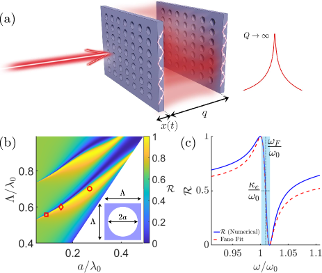
In this Letter, we propose a novel platform for cavity optomechanics, constructed from two suspended PhC slabs in an end-mirror configuration, that relies on photonic bound states in the continuum (BICs). BICs are a general wave phenomenon, where a completely spatially localized mode can exist above the light line Hsu et al. (2016). The double PhC slab cavity (DPhoC), depicted in Fig. 1(a), possesses a large optomechanical coupling due to its near-wavelength length and a moderately low decay rate thanks to the near-perfect trapping of light via the BIC. In contrast to conventional end-mirror systems, this simple system can access purely linear dispersive optomechanical coupling via the BIC mechanism, or purely quadratic coupling via evanescent coupling between the slabs. We argue that near-/sub-wavelength localization of optical modes is a promising strategy for out-of-plane systems and that the DPhoC, with experimentally realistic parameters, can simultaneously possess the required optical and mechanical properties to access the strong quantum cooperativity regime on the single-photon level, without the encumbrance of an outer FP cavity.
Optomechanical Couplings.— For a FP cavity with a movable end mirror, the cavity mode energy, , depends parametrically on the resonator’s out-of-plane displacement and can be expanded around the equilibrium point, , leading to the linear, , and quadratic, , single-photon coupling rates, where is the zero-point motion. We have introduced for convenience the optical frequency shift per displacement, , and its counterpart for the second derivative, . Both and are complex numbers as is the eigenvalue of an open-cavity problem; the imaginary part gives the decay of the cavity mode, . Thus, the real part of the coupling describes dispersive coupling and the imaginary part describes dissipative coupling.
The Double Photonic Crystal Slab Cavity.— Inspired by our recent experimental work Manjeshwar et al. (2020), the model system is built from -thick, GaAs PhC slabs patterned with a square lattice of circular holes, and designed to operate at a wavelength around , where GaAs has a high refractive index of Guha et al. (2017). We stress at this point that the physics discussed in this work is not material dependent (see also appendix F) and we expect the same phenomena in, e.g., SiN-based systems Norte et al. (2016); Bernard et al. (2016); Chen et al. (2017); Nair et al. (2017); Piergentili et al. (2018); Gärtner et al. (2018). To find suitable lattice parameters to achieve a Fano resonance for a single slab, a reflectance map over the air-hole radius and lattice period is calculated. See appendix A for details on the numerical calculations. The lattice parameters used in this section are indicated by the red diamond marker on Fig. 1(b): a period of and radius of . The reflectance spectrum, depicted in Fig. 1(c), shows a pronounced peak near , which corresponds to the Fano resonance. The physics behind this is well captured by coupled-mode theory Haus (1984); Fan et al. (2003) and an exemplary Fano fit is plotted in Fig. 1(c), which allows for the extraction of the mode frequency , external decay rate (radiative loss) , and internal decay rate (e.g., due to materials loss). More details are given in appendix B.
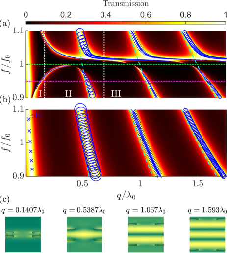
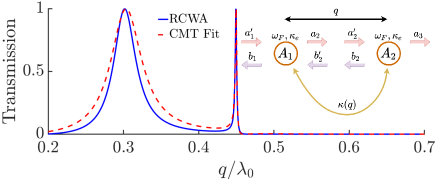
We now consider two such PhC slabs, separated by a distance . The transmittance spectrum is mapped for a range of separations, which is shown in Fig. 2(a). To emphasize that the coupled PhC slabs do not simply lead to a higher reflectivity, but rather new phenomena, we show in Fig. 2(b) the transmittance map of the corresponding double homogeneous-slab system with an effective refractive index (see appendix B) Fan et al. (2003). On top of both transmittance maps, the electromagnetic eigenfrequencies are shown in blue, which are sorted by their even (crosses) or odd (circles) symmetry. The imaginary part of the eigenfrequency measures the radiative loss of the mode and its value is indicated by the marker size. At this stage, no material loss is included.
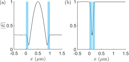
To aid our discussion, we identify three regions based on the slab separation and the consequent dominant form of interaction between the slabs: near field (), intermediate field (), and far field (), separated by white lines in Fig. 2(a). In the far-field, the transmittance maps shown in Figs. 2(a) and (b) exhibit diagonal bands of high transmittance, which is typical FP behaviour. The cavity mode energies of a perfect FP cavity are indicated by the dashed cyan lines. For a given frequency, the transmittance reaches unity for certain separations where a half-integer number of wavelengths can fit into the cavity [see Fig. 2(c)]. In contrast to the homogeneous slabs, which closely follow the cyan lines, the structured slabs show a much more intricate structure on top of this background. Most pertinent to our discussion is the narrowing of the transmittance bands close to the Fano resonance (indicated by the green-dotted line). Further inspection shows that the linewidth of the transmittance spectra approaches zero close to separations corresponding to FP resonances. This behavior is captured by the marker size of the eigenmodes becoming vanishingly small. This is fundamentally different behaviour from a conventional FP cavity where the decay rate is inversely proportional to the cavity length; instead, it is indicative of the evolution of the cavity eigenmode into a BIC.
BICs are peculiar resonances that do not decay over time as there are no available radiation channels due to destructive interference; in principle, they have an infinite quality (Q) factor Hsu et al. (2016). They have been explored in PhC slabs Hsu et al. (2013); Gansch et al. (2016); Kodigala et al. (2017) and double PhC slab structures Li and Yin (2016). In practice, the optical Q-factor is limited by structural disorder and material loss; nevertheless, Q-factors up to have recently been demonstrated Jin et al. (2019). The BICs we observe here are examples of “resonance-trapped” BICs, where the gap acts as the tunable parameter Hsu et al. (2016), which are attractive as they are quite robust to imperfections—one need only change the tuning parameter to compensate for geometrical perturbations. An infinite number of BICs exist for the DPhoC for increasing , but occur at ever smaller gradients, indicating a weaker optomechanical coupling. The long lifetime of the photon in the guided-mode resonance allows a moderately low decay rate even for wavelength-sized cavities. This observation is extremely relevant for microcavities for optomechanics; we can boost by reducing the cavity length down to , but with not limited by the cavity length but rather by the internal loss of the individual slab resonances. A comparison between conventional FP-type optomechanical microcavities and the DPhoC is presented in appendix E. Despite the huge amount of current interest in BICs Hsu et al. (2016), there has been limited study of their utility for optomechanics Zhao and Fang (2019); Hurtado et al. (2020).
The lowest-order BIC is located in the intermediate field, where both coupling via photon tunneling, associated with gradient forces, and propagation, associated with radiation pressure, are relevant. This is illustrated in the electric field plot for in Fig. 2(c) by the deviation from the standard standing-wave mode profile. In this region, we see the same linewidth narrowing, but now the high-transmittance band is highly warped and bends away from the FP line. We also observe the very typical mode splitting of an odd and even mode around the Fano energy (see appendix C). Furthermore, for the lower-energy even mode, there is a crossover from a repulsive to attractive force, i.e., at a certain separation the derivative with respect to displacement vanishes, allowing the DPhoC to access purely quadratic optomechanical coupling: . This is in stark contrast to the regular end-mirror configuration, which can only support repulsive forces. The quadratic coupling relies on gradient forces, which depend on the overlap between the near fields of both slabs, and so exhibits an exponential dependence on separation Suh et al. (2005); Van Thourhout and Roels (2010): , where quantifies the out-of-the-plane decay length of the guided mode. The use of evanescent coupling in optomechanics is nothing new; it has been commonly used to couple light in waveguides to optical microresonators Eichenfield et al. (2007); Anetsberger et al. (2009), as well as microresonators to one another Wiederhecker et al. (2009), but has rarely been utilized for out-of-plane optomechanics Roh et al. (2010); Woolf et al. (2013).
All of the physics displayed in the transmittance map in Fig. 2(a) can be captured extremely well by coupled-mode theory Haus (1984); Fan et al. (2003); Suh et al. (2005). We fit the expressions obtained from coupled-mode theory to the results of numerical simulations to find the value of and find excellent agreement. More importantly, the theory provides an explanation for the family of BICs we observe. By ignoring the direct reflection and transmission of light through the slab, and considering only the interaction via the excited Fano resonances, we find that the BICs are a predominately far-field phenomena found close to the FP resonances where the cavity decay rate completely vanishes in the absence of internal loss. The details are given in appendix C.
Estimated optomechanical coupling strengths.— Since a BIC has no radiative loss, its decay rate is given by some intrinsic loss. To gauge the achievable optomechanics performance of the DPhoC, we must estimate the internal loss channels of the PhC slab. In the following, we explore the DPhoC’s performance for a set of realistic, albeit challenging, experimental parameters. In appendix F, we also explore a more readily attainable parameter set. We consider intrinsic loss governed by material absorption and use experimental studies of GaAs microdisks Michael et al. (2007) to obtain , see appendix F for details. This allows us to estimate the lower bound on the achievable cavity decay rate, assuming that disorder-related loss and finite-size effects of both the beam and the sample can be ignored. We discuss these effects further in appendix F, where it is shown that the DPhoC is surprisingly immune from finite-size effects. We also note that ultrashort Fano cavities have been shown to suffer less from finite-waist effects Naesby and Dantan (2018), illustrating a further advantage of working with compact cavities using BICs.
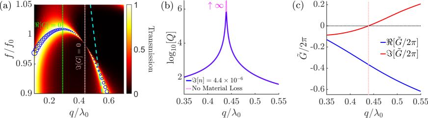
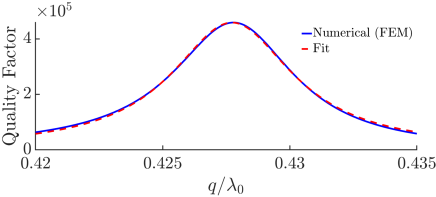
To highlight the large single-photon cooperativity achievable with the DPhoC, we now change the lattice parameters to boost the dispersive linear coupling at the BIC location: a period of , radius of , and thickness of , indicated by the red circle in Fig. 1(b). This system is very practical, with a double-slab structure very close to these parameters already demonstrated Manjeshwar et al. (2020). The transmittance map, shown in Fig. 3(a), exhibits a BIC located in the intermediate zone at (pink dotted line), shown explicitly by a sharp peak in the Q-factor in Fig. 3(b). The Q-factor has a maximum around , which is limited by material absorption, and is similar in magnitude with the highest Q-factors for a BIC reported to date Jin et al. (2019). In Fig. 3(c) we plot and find and at the BIC. Because our system is so compact, we can achieve coupling strengths of the order of tens-hundreds of GHz/nm. This is orders of magnitude larger than conventional out-of-plane systems Thompson et al. (2008); Gärtner et al. (2018) and comparable to values seen for in-plane geometries Chan et al. (2011); Gavartin et al. (2011); Leijssen et al. (2017); Guo et al. (2019). The DPhoC has the advantage that no outer cavity is necessary, as opposed to the MiM geometry Thompson et al. (2008) or multi-element optomechanics approach Xuereb et al. (2012), considerably simplifying fabrication and operation.
The DPhoC has the potential to access the regime of single-photon optomechanics Rabl (2011); Nunnenkamp et al. (2011) by obtaining a large single-photon quantum cooperativity. Using realistic parameters of suspended PhC slabs Norte et al. (2016); Manjeshwar et al. (2020) with a mechanical frequency of and associated effective mass yields a single-photon optomechanical coupling strength of and a considerable ratio of (). These estimated values place our system in the non-resolved sideband regime and firmly in the ultrastrong single-photon coupling regime with , complementing previous works Leijssen et al. (2017); Fogliano et al. (2019). Further, assuming a realistically achievable mechanical Q-factor of Norte et al. (2016); Tsaturyan et al. (2017) yields a single-photon cooperativity Aspelmeyer et al. (2014); Børkje (2020) of , which is similar to Ref. Fogliano et al. (2019) and three orders of magnitude larger than in Refs. Leijssen et al. (2017); Guo et al. (2019). When operating the device at moderate cryogenic temperatures (), we predict a remarkable single-photon quantum cooperativity of (). A value exceeding unity has not been achieved in any cavity optomechanics system before. Thus, the DPhoC offers a promising alternative to proposals in the microwave domain Via et al. (2015); Romero-Sanchez et al. (2018) or to cavity optomechanics with atoms Murch et al. (2008); Brennecke et al. (2008).
At the BIC separation, the optomechanical coupling is purely dispersive. Isolating purely dissipative coupling is also interesting for certain quantum protocols Elste et al. (2009); Xuereb et al. (2011); Wu et al. (2014). To this end, we look at the region around where , indicated by the green line in Fig. 3(a). Here, the DPhoC exhibits a large dissipative coupling: . As we are far from the BIC condition, a large decay rate is found. However, dissipative coupling can be utilized for optomechanical cooling without the need for the ”good cavity” limit Elste et al. (2009).
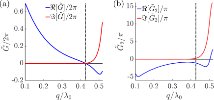
Through tuning of the lattice parameters, it is also possible to place the lowest-order BIC at a point of pure quadratic coupling by shifting it to where vanishes, see Fig. 4(a). The second derivative, , is shown in Fig. 4(b), illustrating that the quadratic coupling is finite where the linear coupling vanishes. We find a coupling of (and a dissipative coupling of ) for a . This compares well with the values of reported by Sankey et al. Sankey et al. (2010), but the DPhoC has the advantage of being many orders of magnitude more compact, and relies on a different mechanism of evanescent coupling rather than radiation pressure. It remains an open question whether the DPhoC system can be optimized to reach the values of reported for state-of-the-art planar PhC cavities Paraïso et al. (2015).
Conclusions.— Combining light propagation in both free-space and guided-mode form, the DPhoC system merges the strengths offered by in-plane and out-of-plane optomechanical systems. We have estimated linear optomechanical coupling rates orders of magnitude larger than conventional end-mirror and MiM platforms, at moderately low optical decay rates, potentially leading to a single-photon quantum cooperativity exceeding unity. The DPhoC constitutes a versatile optomechanics platform able to access different regimes of optomechanical coupling that can be used to explore various quantum protocols in the non-resolved sideband regime Wilson et al. (2015); Rossi et al. (2018); Gut et al. (2019); Guo et al. (2019); Lau and Clerk (2020), in particular in the framework of pulsed optomechanics Vanner et al. (2011); Vanner (2011); Clarke et al. (2020) or frequency-dependent mirrors Naesby and Dantan (2018); Černotík et al. (2019). For instance, the strong frequency dependence of the DPhoC’s mirrors can be exploited in optomechanical cooling, as recently suggested in Ref. Černotík et al. (2019). The geometries described here represent a proof of concept and we expect optimized structures to yield even better performance. We envision many potential pathways from this work, including: squeezing of the guided-mode resonance in space using a defect cavity on the PhC slabs to boost photon-phonon co-localization Notomi et al. (2006), or utilizing phononic BICs Zhao and Fang (2019) alongside their photonic counterparts.
Acknowledgements.
This work was partially supported by Chalmers’ Excellence Initiative Nano, the Knut and Alice Wallenberg Foundation through the Wallenberg Center for Quantum Technology (WACQT), the Swedish Research Council, and the QuantERA project C’MON-QSENS! Some of the numerical calculations were performed on resources provided by the Swedish National Infrastructure for Computing at C3SE.Appendix A Numerical Methods
The numerical calculations are a combination of simulations based on the finite-element frequency domain method (using COMSOL Multiphysics) and rigorous coupled-wave analysis (RCWA) (using the code Liu and Fan (2012)). Where possible, results were obtained using both methods and excellent agreement to within a few percent was found.
Appendix B Fano Resonance
The interference between the direct transmission of light and the guided mode of a structured slab leads to unity reflection near the guided-mode resonance, , with a width . Due to the large Q-factor of the underlying guided modes, Fano resonances are well described by CMT applied to a single resonator with two ports Haus (1984); Fan et al. (2003). Both and can be found by calculating the reflection or transmission spectrum using numerical techniques to solve Maxwell’s equations and fitting the following expressions:
| (1) | |||
| (2) |
which are derived under the assumption that the system possesses time-reversal symmetry, conservation of energy, and even symmetry with respect to the mirror plane. and are given by the reflectivity and transmission of a homogeneous slab with an effective refractive index Fan et al. (2003). For a structured slab with air holes of radius and period , the effective index is given by where . An example of the fit is shown by the red-dashed line in Fig. 1(c). The radiative decay is quantified by and linked to the width of the Fano lineshape (given by the shaded blue region in the plot). It describes the in- and out-coupling of the guided mode to external radiative channels. The inverse of gives the typical travel time of a photon within the slab. Smaller air holes lead to a reduced due to decreased scattering of the in-plane light, but this comes at the price of a larger impact from internal loss Suh et al. (2003), measured by , which includes the impacts of various loss channels such as material loss and lattice imperfections.
Appendix C Bound state in the continuum theory
The DPhoC is modelled as two resonators within CMT, and , which obey the following two coupled first-order differential equations Suh et al. (2005)
| (3) |
where evanescent coupling is described by the real parameter and coupling via photon propagation is described by the complex term . and are the incoming and outgoing field amplitudes on either side of the slabs, and are defined in the inset of Fig. 5. The transmission, , can be found by Fourier transforming, and the remaining parameter, , is found by fitting the spectrum for fixed frequency and variable . An example of this fitting procedure is shown in Fig. 5 by the red-dashed line. The fit is excellent, showing that this simple model captures both near- and far-field coupling between the slabs.
To illustrate why BICs occur for the DPhoC, we will make some drastic simplifications to the CMT that reveal the essential mechanisms more clearly. The physics we are interested in depends on the interaction of the resonances in each slab and not the direct process which is controlled by and , therefore we set them to zero. This “flat-background” approximation is most valid for PhC slabs with large air holes and, hence, a lower effective refractive index. The coupling of the two resonator modes leads to hybridization into even and odd “super-modes” Song et al. (2009):
| (4) |
which have the following energies and decay rates
| (5) | |||
| (6) |
where we have made the approximation that the right-hand side can be evaluated at the Fano energy, . The mode frequency shows a splitting between the even (which is at a lower energy) and the odd mode about the Fano energy, with contributions from both the near-field and far-field coupling, just as we observed in Fig. 2(a). These equations also reveal the presence of BICs: for no internal loss, coupling to output channels vanishes for , which is just the usual FP resonance condition and reveals an infinite number of such BICs. Interestingly, to this approximation, the near-field coupling does not affect the BIC location; the BICs we observe are predominately a far-field phenomena.
Further evidence that we are indeed observing BICs comes from the quadratic dependence of on , where is the slab separation corresponding to a BIC Blanchard et al. (2016). This is confirmed by fitting and is shown in Fig. 6.
Appendix D The near-field region
Here we discuss the near-field region shown in Figs. 2(a) and 2(b), where photon propagation between the slabs is negligible and evanescent coupling dominates. For the structured slabs, this region is indicated by the eigenmodes deviating from the bands of high transmittance. The eigenmodes become very lossy () and so are not shown in Fig. 2(a) for clarity. These modes could be useful for cavity optomechanics if we borrow the MiM philosophy and the DPhoC was placed within a larger cavity to recycle the leaked light.
We also observe an interesting high-transmittance branch for the homogeneous slabs in Fig. 2(b). It derives from a family of leaky modes which do not correspond to FP modes. This is illustrated nicely in Fig. 7, where the electric field profile of the lowest-order FP mode and the near-field-zone mode are compared; the field of the former is concentrated within the cavity between the slabs, and the field of the latter is concentrated much more within the slabs. As the slabs are not structured and the incoming light is normally incident, it cannot be a consequence of near-field coupling and instead we speculate that it is similar in nature to zero-frequency modes seen for single slabs Llorens et al. (2014); Ismail et al. (2016). Note that we do not include Casimir forces, which are derived from vacuum quantum fluctuations and are not present in our classical calculations.
| (MHz) | (GHz/nm) | (kHz) | ||||||
| 17 m | 8.8 | 11.4 | 7.3 | 18 | 49 | |||
| 775 nm | 193 | 250 | 161 | 1100 |
Appendix E Comparison of the DPhoC to a Fabry-Pérot-type optomechanical microcavity
For the end-mirror configuration of length , the linear dispersive coupling rate is given by , where is the zero-point motion and is the cavity frequency. For the MiM geometry, the maximum linear coupling rate is times larger than the corresponding end-mirror geometry of the same total cavity length, where is the reflectivity of the inner membrane. In principle, can be increased as we decrease the length down to (below which no FP resonance is supported). The decay rate of an end-mirror cavity is given by , where is the cavity finesse. This means that is independent of length.
Let us estimate the optomechanical parameter regime achievable with a FP-type optomechanical microcavity, which in turn allows us to compare to the performance of the DPhoC. To this end, we combine parameters from independent realizations of state-of-the-art optical microcavities Wachter et al. (2019) and distributed Bragg reflector (DBR)-based high-reflectivity mechanical resonators Gröblacher et al. (2009); Cole et al. (2011); Weaver et al. (2016) in order to obtain an estimate on the potential of a FP-based optomechanical microcavity. We consider an optical microcavity of length with a finesse of at telecom wavelengths, which has been recently realized in chip-based silicon microcavity arrays Wachter et al. (2019). Note that a slightly smaller finesse of has been achieved in a 5-cm-long FP-based optomechanical system Weaver et al. (2016). Both of these cavities employed multilayer coatings, i.e., DBRs, to achieve such an exceptionally large finesse. Hence, the mechanical resonator has to be realized via a suspended DBR Cole et al. (2011) or a DBR on a mechanical resonator Gröblacher et al. (2009); Weaver et al. (2016) to obtain such high finesse values. These systems have typical mechanical parameters of , and a mechanical quality factor at Gröblacher et al. (2009); Cole et al. (2011); Weaver et al. (2016). Note that the DBR limits the performance of the mechanical resonator, in particular, resulting in a lower mechanical quality factor and larger effective mass compared to state-of-the-art DBR-free mechanical resonators, which routinely achieve values of , . All together, this leads to the set of parameters displayed in Table 1 and, hence, to much less advantageous optomechanical values than the DPhoC we propose in this work, with the exception of a slightly improved ratio.
Also shown in Table 1 are the parameters for the minimal cavity length of of such a hypothetical FP cavity. Despite this microcavity having a larger than the DPhoC we consider, such a system suffers from the ratio being independent of cavity length, and the worse performance of the mechanical resonator compared to PhC-based mechanical resonators. Hence, we conclude that a FP microcavity will lead to a worse performance than a DPhoC system.
Appendix F Estimation of loss channels
F.1 Material absorption loss
To estimate the ultimate upper bounds on the BIC’s Q-factor, we need an estimate of the intrinsic material loss. We extracted material-based absorption for GaAs using Ref. Michael et al. (2007), where a loss rate of was measured for GaAs microdisks at . This yields an absorption coefficient with the group velocity, , estimated as m/s. For the 100-nm-thick membranes we consider in this work, we get a material absorption of about ppm; this is an overestimation of the loss as some of the electric field of the mode will be concentrated in the air-holes rather than the GaAs. The imaginary component of the refractive index can then be found from: Xu et al. (2009). For our operation wavelength of nm, this gives . This value, along with a mechanical quality factor of , will be denoted as parameter set I and displayed in Table 2. This set was used earlier and represents challenging, but achievable, parameters that are state-of-the-art in both mechanics and photonics. Using this value of for a single PhC slab gives a max reflectance of near the Fano resonance.
| Set | |||||||
|---|---|---|---|---|---|---|---|
| (I) | |||||||
| (II) |
For set II, we estimate the corresponding effective for a max reflectance of , which was achieved in a single \chSi_3N_4 PhC slab in Ref. Chen et al. (2017). This yields . This is not entirely appropriate as the devices in the aforementioned reference were limited by scattering rather than material absorption, but it gives an indication of the effects of non-unity reflectance and the resulting optical Q-factor of is in line with values found for typical BIC systems Lee et al. (2014). The parameters for set II are also shown in Table 2.
F.2 Transverse effects
In our estimation of , we have ignored loss from transverse effects such as wavefront curvature, non-perfectly-parallel mirrors, and finite-area structures. These unavoidable limitations are a consequence of incident light coupling into modes located over a finite region of k-space, leading to additional loss channels. Relevant to our discussions is that ultrashort cavities built from Fano mirrors have been shown to suffer less from finite-waist effects Naesby and Dantan (2018). There is also the possibility of designing Fano mirrors with focusing abilities Fattal et al. (2010); Guo et al. (2017). Furthermore, resonance-trapped BICs have been shown to display a large Q-factor over a wide range in k-space Kodigala et al. (2017), and recently the merging of multiple BICs has been used to suppress out-of-plane scattering losses Jin et al. (2019).
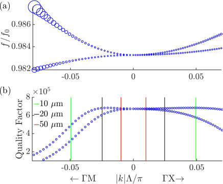
To demonstrate that the DPhoC is surprisingly immune from finite-size effects, we have calculated the Q-factor for wavevectors away from the high-symmetry point of the first Brillouin zone for a square lattice (see Fig. 8). To save simulation time, we explore slices in k-space in the direction from to the other high-symmetry points and . A detailed calculation would integrate over a specified area of k-space—a thorough discussion of including finite-beam-waist size effects in reflection and transmission spectra can be found in the supplementary material of Ref. Manjeshwar et al. (2020). We observe that the mode at is doubly degenerate at the point and splits in energy, which can be seen in Fig. 8(a). Importantly, the Q-factor remains well above in a large region of k-space; this is shown in Fig. 8(b). In realistic devices, there is a compromise between the lateral size of the device, which will affect mechanical properties, and the beam-waist size to achieve maximum slab reflectivities. A Gaussian beam can be represented as a sum of angled plane-wave components weighted by a Gaussian distribution with a standard deviation given by the beam divergence, , where is the beam-waist size. In Fig. 8(b), we represent the beam divergence for beam-waists of 10, 20 and , which are typical values used in experiments Norte et al. (2016); Moura et al. (2018); Gärtner et al. (2018).
F.3 Estimate for SiN-based system
The physics discussed throughout this work is not material dependent and can be expected to be applicable for SiN-based systems Norte et al. (2016); Bernard et al. (2016); Chen et al. (2017); Nair et al. (2017); Piergentili et al. (2018); Gärtner et al. (2018), which are more commonly used in optomechanics. Here, we provide an estimate of the optomechanical parameters obtainable with a such systems. The optical Q-factor of the BIC can be approximated using Xu et al. (2009), , which we have confirmed to be an accurate estimate for GaAs PhC slabs. as small as has been measured for membranes of close to thickness at a wavelength of Serra et al. (2016). As , this gives . Assuming similar optomechanical coupling rates and mechanical properties, then the ultimate achievable optomechanical parameters of a SiN-based DPhoC should be similar to set I in Table 2.
References
- Aspelmeyer et al. (2014) M. Aspelmeyer, T. J. Kippenberg, and F. Marquardt, Rev. Mod. Phys. 86, 1391 (2014).
- Chan et al. (2011) J. Chan, T. P. Mayer Alegre, A. H. Safavi-Naeini, J. T. Hill, A. Krause, S. Gröblacher, M. Aspelmeyer, and O. Painter, Nature 478, 89 (2011).
- Teufel et al. (2011) J. D. Teufel, T. Donner, D. Li, J. W. Harlow, M. Allman, K. Cicak, A. J. Sirois, J. D. Whittaker, K. W. Lehnert, and R. W. Simmonds, Nature 475, 359 (2011).
- Rossi et al. (2018) M. Rossi, D. Mason, J. Chen, Y. Tsaturyan, and A. Schliesser, Nature 563, 53 (2018).
- Delić et al. (2020) U. Delić, M. Reisenbauer, K. Dare, D. Grass, V. Vuletić, N. Kiesel, and M. Aspelmeyer, Science 367, 892 (2020).
- Safavi-Naeini et al. (2013) A. H. Safavi-Naeini, S. Gröblacher, J. T. Hill, J. Chan, M. Aspelmeyer, and O. Painter, Nature 500, 185 (2013).
- Purdy et al. (2013) T. P. Purdy, P.-L. Yu, R. Peterson, N. Kampel, and C. Regal, Phys. Rev. X 3, 031012 (2013).
- Wollman et al. (2015) E. E. Wollman, C. U. Lei, A. J. Weinstein, J. Suh, A. Kronwald, F. Marquardt, A. A. Clerk, and K. C. Schwab, Science 349, 952 (2015).
- Pirkkalainen et al. (2015) J.-M. Pirkkalainen, E. Damskägg, M. Brandt, F. Massel, and M. A. Sillanpää, Phys. Rev. Lett. 115, 243601 (2015).
- Lecocq et al. (2015) F. Lecocq, J. B. Clark, R. W. Simmonds, J. Aumentado, and J. D. Teufel, Phys. Rev. X 5, 041037 (2015).
- Palomaki et al. (2013) T. A. Palomaki, J. D. Teufel, R. W. Simmonds, and K. W. Lehnert, Science 342, 710 (2013).
- Ockeloen-Korppi et al. (2018) C. F. Ockeloen-Korppi, E. Damskägg, J.-M. Pirkkalainen, M. Asjad, A. A. Clerk, F. Massel, M. J. Woolley, and M. A. Sillanpää, Nature 556, 478 (2018).
- Riedinger et al. (2018) R. Riedinger, A. Wallucks, I. Marinković, C. Löschnauer, M. Aspelmeyer, S. Hong, and S. Gröblacher, Nature 556, 473 (2018).
- Thompson et al. (2008) J. D. Thompson, B. M. Zwickl, A. M. Jayich, F. Marquardt, S. M. Girvin, and J. G. E. Harris, Nature 452, 72 (2008).
- Sankey et al. (2010) J. C. Sankey, C. Yang, B. M. Zwickl, A. M. Jayich, and J. G. Harris, Nat. Phys. 6, 707 (2010).
- Clerk et al. (2010) A. A. Clerk, F. Marquardt, and J. G. E. Harris, Phys. Rev. Lett. 104, 213603 (2010).
- Purdy et al. (2010) T. P. Purdy, D. Brooks, T. Botter, N. Brahms, Z.-Y. Ma, and D. M. Stamper-Kurn, Phys. Rev. Lett. 105, 133602 (2010).
- Vanner (2011) M. R. Vanner, Phys. Rev. X 1, 021011 (2011).
- Paraïso et al. (2015) T. K. Paraïso, M. Kalaee, L. Zang, H. Pfeifer, F. Marquardt, and O. Painter, Phys. Rev. X 5, 041024 (2015).
- Gavartin et al. (2011) E. Gavartin, R. Braive, I. Sagnes, O. Arcizet, A. Beveratos, T. J. Kippenberg, and I. Robert-Philip, Phys. Rev. Lett. 106, 203902 (2011).
- Leijssen et al. (2017) R. Leijssen, G. R. La Gala, L. Freisem, J. T. Muhonen, and E. Verhagen, Nature Commun. 8, 1 (2017).
- Guo et al. (2019) J. Guo, R. Norte, and S. Gröblacher, Phys. Rev. Lett. 123, 223602 (2019).
- Gigan et al. (2006) S. Gigan, H. Böhm, M. Paternostro, F. Blaser, G. Langer, J. Hertzberg, K. C. Schwab, D. Bäuerle, M. Aspelmeyer, and A. Zeilinger, Nature 444, 67 (2006).
- Arcizet et al. (2006) O. Arcizet, P.-F. Cohadon, T. Briant, M. Pinard, and A. Heidmann, Nature 444, 71 (2006).
- Kleckner and Bouwmeester (2006) D. Kleckner and D. Bouwmeester, Nature 444, 75 (2006).
- Xuereb et al. (2012) A. Xuereb, C. Genes, and A. Dantan, Phys. Rev. Lett. 109, 223601 (2012).
- Nair et al. (2017) B. Nair, A. Naesby, and A. Dantan, Opt. Lett. 42, 1341 (2017).
- Piergentili et al. (2018) P. Piergentili, L. Catalini, M. Bawaj, S. Zippilli, N. Malossi, R. Natali, D. Vitali, and G. Di Giuseppe, New. J. Phys. 20, 083024 (2018).
- Gärtner et al. (2018) C. Gärtner, J. P. Moura, W. Haaxman, R. A. Norte, and S. Gröblacher, Nano Lett. 18, 7171 (2018).
- Wei et al. (2019) X. Wei, J. Sheng, C. Yang, Y. Wu, and H. Wu, Phys. Rev. A 99, 023851 (2019).
- Xuereb et al. (2013) A. Xuereb, C. Genes, and A. Dantan, Phys. Rev. A 88, 053803 (2013).
- Fan et al. (2003) S. Fan, W. Suh, and J. D. Joannopoulos, J. Opt. Soc. Am. A 20, 569 (2003).
- Chen et al. (2017) X. Chen, C. Chardin, K. Makles, C. Caër, S. Chua, R. Braive, I. Robert-Philip, T. Briant, P.-F. Cohadon, A. Heidmann, et al., Light Sci. Appl. 6, e16190 (2017).
- Norte et al. (2016) R. A. Norte, J. P. Moura, and S. Gröblacher, Phys. Rev. Lett. 116, 147202 (2016).
- Manjeshwar et al. (2020) S. K. Manjeshwar, K. Elkhouly, J. M. Fitzgerald, M. Ekman, Y. Zhang, F. Zhang, S. M. Wang, P. Tassin, and W. Wieczorek, Appl. Phys. Lett. 116, 264001 (2020).
- Suh et al. (2005) W. Suh, O. Solgaard, and S. Fan, J. Appl. Phys. 98, 033102 (2005).
- Shuai et al. (2013) Y. Shuai, D. Zhao, Z. Tian, J.-H. Seo, D. V. Plant, Z. Ma, S. Fan, and W. Zhou, Opt. Express 21, 24582 (2013).
- Liu et al. (2017) Y. Liu, W. Zhou, and Y. Sun, Sensors 17, 1861 (2017).
- Kemiktarak et al. (2012) U. Kemiktarak, M. Metcalfe, M. Durand, and J. Lawall, Appl. Phys. Lett. 100, 061124 (2012).
- Woolf et al. (2013) D. Woolf, P.-C. Hui, E. Iwase, M. Khan, A. W. Rodriguez, P. Deotare, I. Bulu, S. G. Johnson, F. Capasso, and M. Loncar, Opt. Express 21, 7258 (2013).
- Makles et al. (2015) K. Makles, T. Antoni, A. Kuhn, S. Deléglise, T. Briant, P.-F. Cohadon, R. Braive, G. Beaudoin, L. Pinard, C. Michel, et al., Opt. Lett. 40, 174 (2015).
- Stambaugh et al. (2015) C. Stambaugh, H. Xu, U. Kemiktarak, J. Taylor, and J. Lawall, Ann. Phys. (Berlin) 527, 81 (2015).
- Roh et al. (2010) Y.-G. Roh, T. Tanabe, A. Shinya, H. Taniyama, E. Kuramochi, S. Matsuo, T. Sato, and M. Notomi, Phys. Rev. B 81, 121101 (2010).
- Naesby and Dantan (2018) A. Naesby and A. Dantan, Opt. Express 26, 29886 (2018).
- Černotík et al. (2019) O. Černotík, A. Dantan, and C. Genes, Phys. Rev. Lett. 122, 243601 (2019).
- Hsu et al. (2016) C. W. Hsu, B. Zhen, A. D. Stone, J. D. Joannopoulos, and M. Soljačić, Nat. Rev. Mater. 1, 1 (2016).
- Guha et al. (2017) B. Guha, S. Mariani, A. Lemaître, S. Combrié, G. Leo, and I. Favero, Opt. Express 25, 24639 (2017).
- Bernard et al. (2016) S. Bernard, C. Reinhardt, V. Dumont, Y.-A. Peter, and J. C. Sankey, Opt. Lett. 41, 5624 (2016).
- Haus (1984) H. A. Haus, Waves and fields in optoelectronics (Prentice-Hall, Englewodd Cliffs, New Jersey 07632, 1984).
- Hsu et al. (2013) C. W. Hsu, B. Zhen, J. Lee, S.-L. Chua, S. G. Johnson, J. D. Joannopoulos, and M. Soljačić, Nature 499, 188 (2013).
- Gansch et al. (2016) R. Gansch, S. Kalchmair, P. Genevet, T. Zederbauer, H. Detz, A. M. Andrews, W. Schrenk, F. Capasso, M. Lončar, and G. Strasser, Light Sci. Appl. 5, e16147 (2016).
- Kodigala et al. (2017) A. Kodigala, T. Lepetit, Q. Gu, B. Bahari, Y. Fainman, and B. Kanté, Nature 541, 196 (2017).
- Li and Yin (2016) L. Li and H. Yin, Sci. Rep. 6, 26988 (2016).
- Jin et al. (2019) J. Jin, X. Yin, L. Ni, M. Soljačić, B. Zhen, and C. Peng, Nature 574, 501 (2019).
- Zhao and Fang (2019) M. Zhao and K. Fang, Opt. Express 27, 10138 (2019).
- Hurtado et al. (2020) C. B. R. Hurtado, J. Dickmann, F. F. Bruns, T. Siefke, and S. Kroker, Opt. Express 28, 20106 (2020).
- Van Thourhout and Roels (2010) D. Van Thourhout and J. Roels, Nature Photon. 4, 211 (2010).
- Eichenfield et al. (2007) M. Eichenfield, C. P. Michael, R. Perahia, and O. Painter, Nature Photon. 1, 416 (2007).
- Anetsberger et al. (2009) G. Anetsberger, O. Arcizet, Q. P. Unterreithmeier, R. Rivière, A. Schliesser, E. M. Weig, J. P. Kotthaus, and T. J. Kippenberg, Nat. Phys. 5, 909 (2009).
- Wiederhecker et al. (2009) G. S. Wiederhecker, L. Chen, A. Gondarenko, and M. Lipson, Nature 462, 633 (2009).
- Michael et al. (2007) C. Michael, K. Srinivasan, T. Johnson, O. Painter, K. Lee, K. Hennessy, H. Kim, and E. Hu, Appl. Phys. Lett. 90, 051108 (2007).
- Rabl (2011) P. Rabl, Phys. Rev. Lett. 107, 063601 (2011).
- Nunnenkamp et al. (2011) A. Nunnenkamp, K. Børkje, and S. M. Girvin, Phys. Rev. Lett. 107, 063602 (2011).
- Fogliano et al. (2019) F. Fogliano, B. Besga, A. Reigue, P. Heringlake, L. M. de Lépinay, C. Vaneph, J. Reichel, B. Pigeau, and O. Arcizet, arXiv preprint arXiv:1904.01140 (2019).
- Tsaturyan et al. (2017) Y. Tsaturyan, A. Barg, E. S. Polzik, and A. Schliesser, Nature Nanotech. 12, 776 (2017).
- Børkje (2020) K. Børkje, Phys. Rev. A 101, 053833 (2020).
- Via et al. (2015) G. Via, G. Kirchmair, and O. Romero-Isart, Phys. Rev. Lett. 114, 143602 (2015).
- Romero-Sanchez et al. (2018) E. Romero-Sanchez, W. P. Bowen, M. R. Vanner, K. Xia, and J. Twamley, Phys. Rev. B 97, 024109 (2018).
- Murch et al. (2008) K. W. Murch, K. L. Moore, S. Gupta, and D. M. Stamper-Kurn, Nat. Phys. 4, 561 (2008).
- Brennecke et al. (2008) F. Brennecke, S. Ritter, T. Donner, and T. Esslinger, Science 322, 235 (2008).
- Elste et al. (2009) F. Elste, S. M. Girvin, and A. A. Clerk, Phys. Rev. Lett. 102, 207209 (2009).
- Xuereb et al. (2011) A. Xuereb, R. Schnabel, and K. Hammerer, Phys. Rev. Lett. 107, 213604 (2011).
- Wu et al. (2014) M. Wu, A. C. Hryciw, C. Healey, D. P. Lake, H. Jayakumar, M. R. Freeman, J. P. Davis, and P. E. Barclay, Phys. Rev. X 4, 021052 (2014).
- Wilson et al. (2015) D. Wilson, V. Sudhir, N. Piro, R. Schilling, A. Ghadimi, and T. J. Kippenberg, Nature 524, 325 (2015).
- Gut et al. (2019) C. Gut, K. Winkler, J. Hoelscher-Obermaier, S. Hofer, R. M. Nia, N. Walk, A. Steffens, J. Eisert, W. Wieczorek, J. Slater, et al., arXiv preprint arXiv:1912.01635 (2019).
- Lau and Clerk (2020) H.-K. Lau and A. A. Clerk, Phys. Rev. Lett. 124, 103602 (2020).
- Vanner et al. (2011) M. R. Vanner, I. Pikovski, G. D. Cole, M. Kim, Č. Brukner, K. Hammerer, G. J. Milburn, and M. Aspelmeyer, Proc. Natl. Acad. Sci. U.S.A. 108, 16182 (2011).
- Clarke et al. (2020) J. Clarke, P. Sahium, K. E. Khosla, I. Pikovski, M. S. Kim, and M. R. Vanner, New. J. Phys. 22, 063001 (2020).
- Notomi et al. (2006) M. Notomi, H. Taniyama, S. Mitsugi, and E. Kuramochi, Phys. Rev. Lett. 97, 023903 (2006).
- Liu and Fan (2012) V. Liu and S. Fan, Computer Phys. Commun. 183, 2233 (2012).
- Suh et al. (2003) W. Suh, M. F. Yanik, O. Solgaard, and S. Fan, Appl. Phys. Lett. 82, 1999 (2003).
- Song et al. (2009) H. Y. Song, S. Kim, and R. Magnusson, Opt. Express 17, 23544 (2009).
- Blanchard et al. (2016) C. Blanchard, J.-P. Hugonin, and C. Sauvan, Phys. Rev. B 94, 155303 (2016).
- Llorens et al. (2014) J. M. Llorens, J. Buencuerpo, and P. A. Postigo, Appl. Phys. Lett. 105, 231115 (2014).
- Ismail et al. (2016) N. Ismail, C. C. Kores, D. Geskus, and M. Pollnau, Opt. Express 24, 16366 (2016).
- Wachter et al. (2019) G. Wachter, S. Kuhn, S. Minniberger, C. Salter, P. Asenbaum, J. Millen, M. Schneider, J. Schalko, U. Schmid, A. Felgner, et al., Light Sci. Appl. 8, 1 (2019).
- Gröblacher et al. (2009) S. Gröblacher, J. B. Hertzberg, M. R. Vanner, G. D. Cole, S. Gigan, K. Schwab, and M. Aspelmeyer, Nat. Phys. 5, 485 (2009).
- Cole et al. (2011) G. D. Cole, I. Wilson-Rae, K. Werbach, M. R. Vanner, and M. Aspelmeyer, Nat. Commun. 2, 1 (2011).
- Weaver et al. (2016) M. J. Weaver, B. Pepper, F. Luna, F. M. Buters, H. J. Eerkens, G. Welker, B. Perock, K. Heeck, S. de Man, and D. Bouwmeester, Appl. Phys. Lett. 108, 033501 (2016).
- Xu et al. (2009) T. Xu, M. S. Wheeler, H. E. Ruda, M. Mojahedi, and J. S. Aitchison, Opt. Express 17, 8343 (2009).
- Lee et al. (2014) J. Lee, B. Zhen, S.-L. Chua, O. Shapira, and M. Soljačić, Opt. Express 22, 3724 (2014).
- Fattal et al. (2010) D. Fattal, J. Li, Z. Peng, M. Fiorentino, and R. G. Beausoleil, Nature Photon. 4, 466 (2010).
- Guo et al. (2017) J. Guo, R. A. Norte, and S. Gröblacher, Opt. Express 25, 9196 (2017).
- Moura et al. (2018) J. P. Moura, R. A. Norte, J. Guo, C. Schäfermeier, and S. Gröblacher, Opt. Express 26, 1895 (2018).
- Serra et al. (2016) E. Serra, M. Bawaj, A. Borrielli, G. Di Giuseppe, S. Forte, N. Kralj, N. Malossi, L. Marconi, F. Marin, F. Marino, et al., AIP Adv. 6, 065004 (2016).