Beam Divergence Reduction of Vortex Waves with a Tailored Lens and a Tailored Reflector
Abstract
In this paper, we present a tailored lens and a tailored reflector in order to reduce the large beam divergence inherent to Orbital Angular Momentum waves (OAM waves/Vortex waves) that are generated by an Uniform Circular Patch Antenna Array (UCA) at . The tailored lens and the tailored reflector are designed by the shape function (5) and (9) around the antenna’s center axis, respectively. The tailored lens is compared to UCA without and with conventional lens. The simulated and measured results show a significant improvement when using the tailored lens. Following, a tailored reflector is implemented and compared to UCA without and with conventional reflector. Firstly, the two reflectors are simulated with an impressed field source to neglect the influence of the UCA. The simulated results of the two reflectors show that the tailored reflector has a better performance than the conventional reflector when the height of the reflector is less than around and when the opening angle of the reflector is less than ∘ (for UCA with of ). In addition, the reflectors are simulated with real UCA with different shapes of PCB, which can disturb the reflected waves from the reflector. Two lenses and two reflectors are manufactured and measured in an anechoic chamber and compared to the simulation results. This paper shows that the vortex waves needs a special lens or a special reflector to reduce effictively the beam divergence especially when the radius of the UCA is very large.
Keywords:
Vortex Waves, Orbital Angular Momentum OAM, Spiral Waves, Patch Antenna Array, Reflector, Lens.I Introduction
In recent years, vortex waves have attracted the interest of many scientists, especially after the successful utilization of vortex waves in the optics domain [1]. Electromagnetic waves can carry Spin Angular Momentum (SAM) (intrinsic rotation) and Orbital Angular Momentum (OAM) (extrinsic rotation i.e macroscopic helical phase) [2]. The vortex waves are characterized by a helical phase distribution that changes linearly around the beam axis, a doughnut-shaped radiation pattern, and by the phase singularity, i.e. the phase along the beam axis is not determinable. The following equation describes the vortex waves , where is the amplitude of the electric field strength, is the geometric azimuthal angle and is the OAM mode order. There are many possibilities to generate OAM waves such as elliptical patch antennas [3], uniform circular patch antenna arrays (UCA) [4], spiral phase plates [5], holographic plates [6], metasurfaces [7], and reflectors [8]. Each of these approaches have advantages and disadvantages, regarding e.g. costs, fabrication simplicity, integration capability, simple design and implementation, simple feeding etc. Many researchers have published regarding OAM beams with different mode orders (), which is an additional degree of freedom in signal coding. This feature of the OAM yields additional capacity and spectral efficiency enabling the transmission of multiple signals of the same frequency within the same time interval. Nevertheless, the vortex waves are suffering from the increased beam divergence, especially when higher OAM mode orders are utilized [9]. This large beam divergence can be an issue for many applications, such as in the wireless communication. Several publications tried to reduce the beam divergence by using Fabry-Perot Cavity [10], by using lenses [11], [12], [13], [14], by using antenna arrays in UCA [15] , and by using reflectors [16], [17], [18] , [19], [20]. Each of these approaches have issues with the design, with the integration, or with the manufacturing. Here, we utilize the uniform circular patch antenna array approach and design a tailored lens and a tailored reflector to overcome the inherent divergence of the vortex beams. The simulated and measured results of the two approaches are compared to UCA and to the conventional lens and conventional reflector. In the following, we review the simulated and the measured results of the lens in Section II and III. Then, we show the design process of the reflector with impressed source and with real UCA in Section IV and V. In Section VI, we present the measured results of the reflector.
II Design of Uniform Circular Array (UCA)
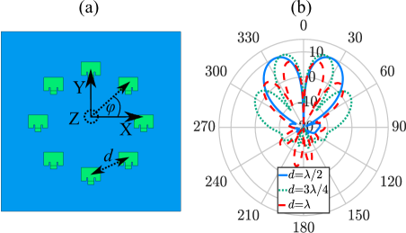
At first, a single rectangular patch antenna element is designed on a printed circuit board (PCB). The length and the width of the patch antenna are (about ) and , respectively. Two insets in the antenna enable the matching of the antenna to in order to maximize the realized gain, which is . The antenna has a Y-polarization with respect to the coordinate system given in Fig. 1. In the following, this single antenna is extended to form a circular patch antenna array of elements with a distance between the adjacent antennas of = (cf. Fig. 1) in order to obtain the desired OAM wave having a radiation pattern of doughnut type with increased gain and lower side and back lobes. The slight asymmetry of the radiation pattern is due to the single-sided, hence asymmetric feeding of each patch antenna element. This asymmetry becomes more noticeable for larger radii. The reflection coefficient of the antennas are between and at the operating frequency of . The gain of the planar circular patch antenna array amounts to about for the OAM mode . The footprint of the underlying PCB board is . The UCA is designed with the full-wave simulator FEKO that applies the Method of Moments (MoM) providing a high simulation efficiency for this setup. The operating frequency is set to . These antennas are atched on a Rogers RO4003C substrate with a height of and a relative permittivity of . The phase shift between each pair of adjacent antennas is defined as port feeding phase in the full-wave simulator FEKO to obtain the OAM mode with mode order . This phase shift is defined by the following relation
| (1) |
where is the number of single antennas and is the mode order of the vortex waves.
III design of conventional and tailored lens
In this Section, the conventional and the tailored lens are designed and compared to each other. The material of the two lenses is polypropylene with a relative permittivity of . Therefore, the antennas has to be redesigned accordingly due to the change of the effective permittivity. The new length and the width of the patch antenna element are thus and , respectively. The reflection coefficient amounts to for one patch antenna element at . The conventional lens consists of two parts, namely the cylindrical dielectric part and the ellipsoidal part. The cylindrical dielectric part shifts the focal point into the center of the UCA and the ellipsoidal part converts the spherical waves into narrower plane waves. Therefore, the gain of the UCA is expected to be increased and the divergence will be correspondingly reduced. The design of the conventional lens uses the following equations [21] according to Fig. 2 (a,c,e)
| (2) |
| (3) |
| (4) |
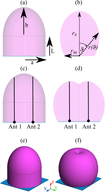
where and are the semi-minor and semi-major axis of the ellipsoidal part along the -axis, where depends on the target directivity in []. is the length of the extension part, and is the operating wavelength, which is at . The equation (4) seems to assume an aperture efficiency of %, which is most propably not true for OAM-antennas. is chosen for to make the assembling of the lens with the PCB board easier. Hence, and are and , respectively. On the other hand, the principle of Fermat allows to design a lens for a single patch antenna [22]
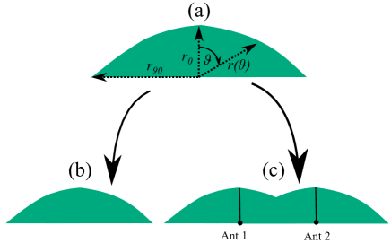
| (5) |
where and are the refractive indices of the lens and the air with values of and , respectively. () is the radius of the lens, which depends on the polar angle , and is the radius at = 0∘. The shape function (5) is used to design the tailored lens by sweeping this function which has been shifted to align with the pacth antenna’s center arround the -axis, as shown in Fig. 2 (b,d,f). Similar to the conventional lens, the entire PCB board is covered to simplify the assembling of the lens with the UCA.
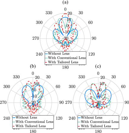
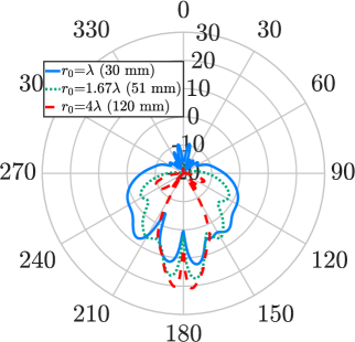
Thus, the radius at the polar angle ∘ and ∘ are about and , respectively. The larger is, the greater the gain of the radiation pattern and the divergence will be thus correspondingly reduced. The gain of the UCA for the mode order is increased with the conventional lens from about to as depicted in Fig. 3 (b). For an of the gain shall be with a single antenna element. In addition to the increased gain, one can notice that the number of the side lobes is increased, which leads automatically to reduction of the gain and the beam divergence. The tailored lens (cf. Fig. 3 (b)) shows a significant decrease of the beam divergence with a maximum gain of . Moreover, the number of the side lobes is less than in the case of the conventional lens. One can notice that the aperture of the two lenses are not equal. The effective aperture , and the physical aperture are defined with
| (6) |
| (7) |
| (8) |
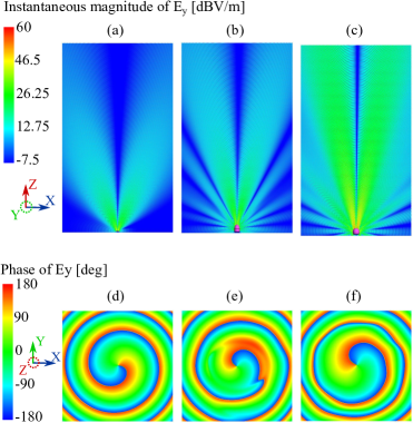
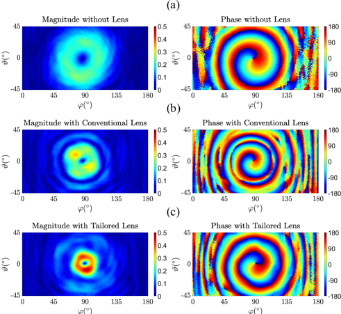
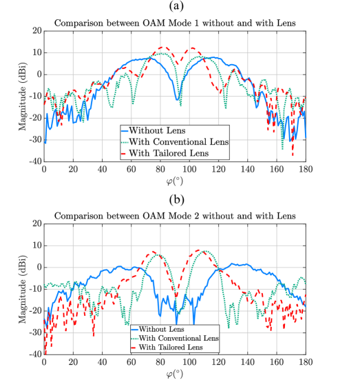
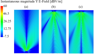
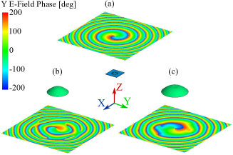
where is the wavelength in the free space, is the gain of the antenna, and is the largest radius of the lens. The ratio between the effective aperture and the physical aperture is called the aperture efficiency , which is a parameter between and , that measures how good is the antenna by receiving the radio wave power, which enters in the physical aperture. The conventional lens and the tailored lens have an aperture efficiency of and , respectively. This is an advantage of the tailored lens compared to the conventional lens. In Fig. 3 (a), the mode order is depicted. One can notice that the conventional lens is deforming the mode contrary to the tailored lens, which is enhancing the gain from to . This is due to the placement of the antennas, which are not in the focal point in the case of the conventional lens. This is a very good advantage of the tailored lens compared to the conventional lens, especially when the lens is used in the OAM target localization, where several mode orders are needed to find the direction of the target. In Fig. 3 (c), in the case of mode (cf. Fig. 3 (b)) the two lenses have carried out a similar gain enhancement, but with an advantage of less side lobes in the case of the tailored lens. Please note that the maximum reached gain with the second mode order can be achieved with a distance of about between the adjucent antenna element (cf. Fig. 1 (a)). Therefore, this leads to increase the size of the lens and to use more material, which is not the case of the tailored lens, which can save material and weight especially in the middle. This is an additionally advantage of the tailored lens compared to the conventional lens. Fig. 4 shows the instantaneous electric field and the phase distribution of the OAM mode order of the case without lens (a,d), with conventional lens (b,e), and with tailored lens (c,f).
IV Lens fabrication and measurements
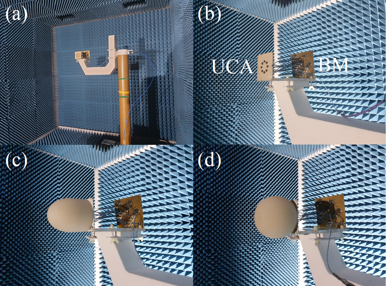
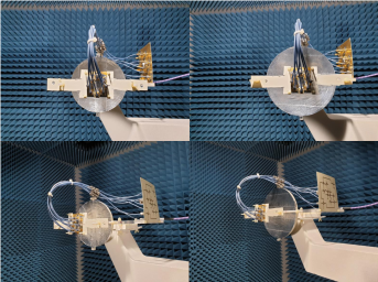
The designed conventional lens and tailored lens in the previous section have been manufactured by an external company. The measurement is performed in an anechoic chamber in order to avoid unwanted reflections and distortions. A vector network analayzer ZVA from Rohde & Schwarz is used at . The VNA is in a control room and connected with the antennas by two coaxial cables with a length of . A horn antenna is used as a transmitter and the lens with UCA and the Butler matrix (BM), which is providing different OAM mode orders, are used as a receiver. The distance between the transmitter and the receiver is about . The lens with UCA and BM are mounted on a rotary table, which is rotating in the azimuth angle from to and in the elevation angle from till . The provided mode order is provided by the BM, which is connected to the UCA by eight coaxial cables of equal length of (cf. Fig. 5). The two lenses are assembled separately on the UCA.
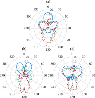
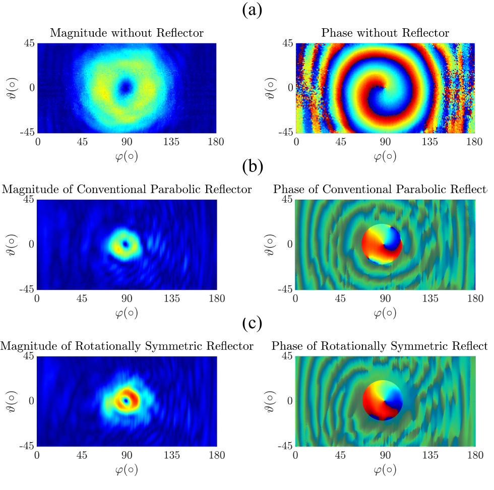
In Fig. 6, the gain of the case without lens (a), with conventional lens (b), and with tailored lens (c) are depicted, respectively. It is easy to observe that the tailored lens has a much better performance compared to the two other cases. The beam divergence is reduced, furthermore, the gain is increased from to and from to for the case of the conventional and the tailored lens, respectively. Fig. 6 shows also the phase distribution of the three cases. The three cases are showing a phase distribution of a one helix, which is a sign of the first mode order. The number of the helices indicates the mode order and the direction of the rotation indicates the sign of the mode order. The sign is positive when the helix is rotating clockwise in the propagation direction and it is negative when the helix is rotating counterclockwise. Fig. 7 shows the magnitude of the three cases for mode and , respectively. One can remark that the gain in the center of of the doughnut is not (linear), like the ideal case. This is due to many reasons, such as the not exact alignment between the transmitter and the receiver, and due to the reflections in the BM and the cables, which are not also ideal. One can also see that the higher the mode order is, the larger the vortex beam is.
V design of conventional and tailored reflector with impressed field source
Likewise the lens, Fermat’s principle allows for a conventional reflector for a point source [22] to be designed, where () is the radius of the reflector depending on the polar angle , is the radius at = 0∘, is the refractive index of the air with a value of 1
| (9) |
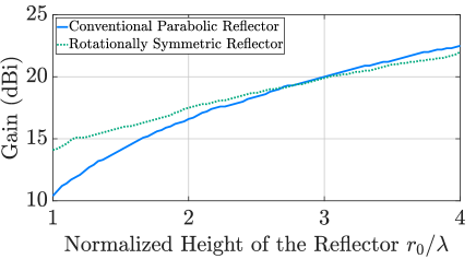
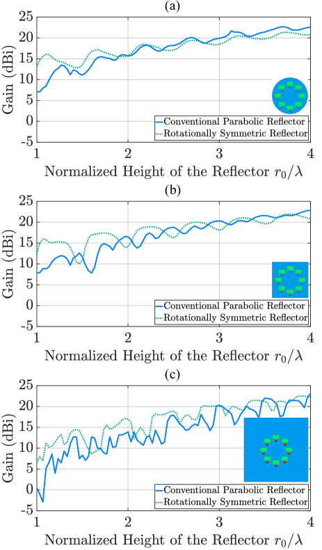
The tailored reflector is designed by sweeping the shape function which also has been shifted to align with the pacth antenna’s center arround the -axis (9), as shown in Fig. 8 (a,c). The two reflectors depend on two parameters, the radius and the angle . The radius depends on how large the reflector is and on the expected gain. A large reflector leads to higher gain. Consequently, the divergence of the vortex waves will be reduced due to an increased focusing of the radiation pattern. The angle is adjuted from ∘ till ∘. The tailored reflector will be compared to UCA without reflector and to UCA with conventional reflector. In Fig. 9 the gain of the two reflector depending on the height is depicted, where we observe that the performance of the tailored reflector is better than the conventional reflector, especially till the height of . Beyond there is no huge gain difference between the conventional reflector and the tailored reflector. However, the tailored reflector continues to show a better reduction in the divergence because the maximum gain still close to the center of the OAM waves (cf. table 1). These results are derived without the influence of the circular antenna array, which may cause some reflections and diffractions of the reflected waves. Therefore, it is easier to compare the two reflectors.
| Opening angle (∘) | Opening angle (∘) | |
| (mm) | (Conventional reflector) | (Tailored reflector) |
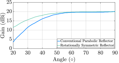
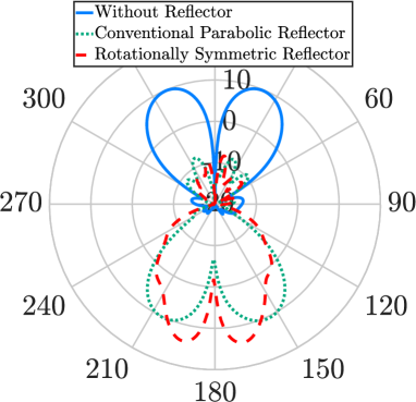
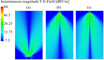
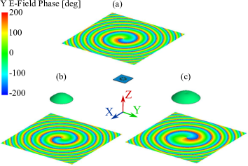
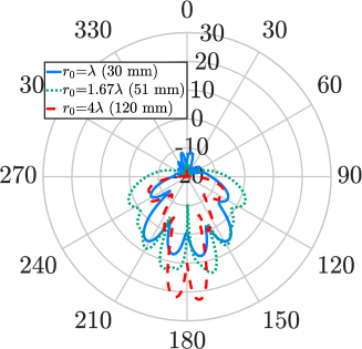
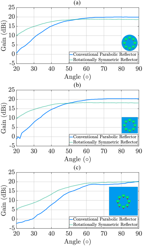
In Fig. 10 the two reflectors are compared for several angle . As we can see the tailored reflector has also a better performance till the angle of ∘. In Fig. 11 the simulated radiation pattern of the impressed field source at = 0∘ without reflector, with conventional reflector and with tailored reflector are depicted. The height is and the angle is from ∘ till ∘. The two reflectors are reducing the divergence from about at angle ∘ to (conventional) at angle ∘ and to (tailored) at angle ∘. One can notice that the tailored reflector is causing some enlargement. This is mainly due to the cut of the reflector in the center, which let some rays to propagate into the second part of the reflector, where undesired reflections can occur. This will not occur when the radius of the UCA is too big compared to the of the reflector. In Figs. 12 and 13 the instantaneous electric field and the phase distribution (helical) of the cases are presented. The vortex waves are still achieved after the reflection with the reflectors, but with the opposite mode, namely instead of . The height of the reflectors is and the angle is from ∘ till ∘.
VI reflector evaluation including real feeding antenna structure
In the last section, the cases are presented with impressed field source, to simplify the interpretation of the behavior of the reflectors. In this section, the reflectors are simulated with real UCA. Three different models are designed. The first model is a circular shaped PCB with a diameter of . The second and the third model have a rectangular shaped PCB with and size, respectively. Fig. 14 shows the gain depending on the height . One can recognize the influence of the reflector height. The oscillating of the gain is due to the reflection and the diffraction on the board of the transmitter. Standing waves occur between the UCA and the reflector. The conventional reflector has more negative influence on the patch antenna than the tailored reflector, which is an advantage for the tailored reflector. The circular shaped PCB has less influence on the vortex waves. In Fig. 16 the gain depending on the angle with a height of is presented. In Figs. 15 and 17 the radiation pattern in D at = 0∘ of the conventional reflector and the tailored reflector for the mode order for three different heights of , , and are presented. The tailored reflector works well from the height of contrary to the conventional reflector, which is showing a nice OAM beam from the height of 1.67. In Figs. 18 and 19 the instantaneous electric field and the phase distribution of the three cases with the real UCA () with a height of and with an angle from ∘ till ∘ are presented. One can observe that the helical phase distribution of the conventional reflector is distorted. The side lobes are very clear due to the existence of the antenna array in front of the reflector. After the reflection with the reflectors, the vortex waves are still achieved, but with the opposite mode, namely from mode to mode . Fig. 20 shows the radiation pattern of the mode orders , and with a height of and an angle of ∘. In the case of mode order , the tailored reflector is increasing the gain from to , unlike the conventional reflector, that is decreasing the gain till . This is similar to the tailored lens. This is obviously an additional advantage for the tailored reflector compared to the conventional reflector. For the mode order , the gain of the conventional and tailored reflector is increased from about till and , respectively. The tailored reflector has and more than the UCA without reflector and the conventional reflector, respectively. For the mode order , the gain is increased from till and for the conventional reflector and the tailored reflector, respectively. The reason of the lower gain in the case of mode is due to the higher beam divergence than the mode . Same as the tailored lens, the tailored reflector has also an advantage of saving weight and material compared to the conventional reflector. This is when higher mode order shall be used, which can need higher distance between the adjucent antennas. Moreover, when the number of antennas shall be incread for the utilization of several mode orders. Please note that we are limited with manufacturing and with the equipments that we have, therefore we didn’t make a larger tailored reflector, where it is easier to observe the benefits of the tailored reflector compared to the conventional reflector.
VII reflector fabrication and measurements
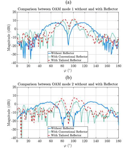
In the same way to the lens, a conventional reflector and a tailored reflector are manufactured with a height of and an opening angle of ∘ to be measured in the anechoic chamber on a rotary tabel. The reflectors are also manufactured with polypropylene, which has to be covered with aluminium foil in order to reflect the incoming waves. The reflector is assembled with UCA and with BM. (cf. Fig 21). In Fig. 22 the beam divergence of the mode order is obviously reduced. In addition, the gain of the tailored reflector has more than the antennas without reflector (in contrast to the simulated results) and more than the conventional reflector (approximately same as the simulated results). The same figure shows also the phase distribution of the three cases, which is a helical phase distribution of the first OAM mode order. Please note that the phase distribution, where the amplitude is very high, is what we are aiming for. Fig. 23 shows the magnitude of the mode order and . The mode order has a gain enhancement of and compared to the UCA without reflector and to the UCA with conventional reflector, respectively. Please note that the measurement has many issues than the simulation due to reasons. On one hand, the reflectors are not % smooth. On the other hand, the aluminium layer are not perfectly glued. Moreover, the antennas are fixed with a piece of plastic, which will cause some absorption and delay of the waves. Thus, the antennas and the reflector are not perfectly aligned. Finally, the antennas are fed with eight coaxial cables, which may interfere with the path of the waves. In order to avoid such an issue, one can integrate the BM or the power divider with the board of the antennas, otherwise one can use two reflectors such as cassegrain reflectors.
Conclusion
In this paper, a novel lens and reflector (tailored) are designed for OAM waves in order to overcome the large beam divergence inherent to OAM waves generated by uniform circular patch array UCA. The lens and the reflector are compared to the conventional lens and to the conventional reflector. The simulations and the measurements show that the tailored lens and the tailored reflector have a better performance than the conventional one. The tailored lens with a of has a gain enhancement of (simulated) and (measured) compared to the gain of UCA without lens and for the first mode order. This gain enhancement is better than the conventional lens, which shows an improvement of only (simulated) and (measured). On the other hand, the tailored reflector with a height of and an angle of 45∘ and with UCA (rectangular shaped PCB ) has a gain enhancement of (simulated) and (measured) compared to the gain of UCA without reflector and for the first mode order. The conventional lens has less gain enhancement of only (simulated) and (measured). In addition, the results of the tailored reflector show that the tailored reflector is more efficient than the conventional reflector until it reaches a height of and an angle of ∘, separately. Moreover, the tailored lens and reflector have also additional advantage. This advantage appears when higher mode order shall be used, which need a higher distance between the adjucent antennas in order to get the maximum gain with less sie lobes. Furthermore, when the number of antennas shall be incread for the utilization of several mode orders in the case of OAM target localization. This two tailored component can save weight and material compared to the conventional lens and reflector. In conclusion, the lens has a big advantage for clear results compared to the reflector. The size of the antennas is not a problem for the lens, in contrast to the reflector where the vortex waves can be disturbed by the UCA and the cables, which are on the way of the waves. Nevertheless, the lens consume too much material, which leads to limit the gain enhancement.
Acknowledgment
This work was funded by the Deutsche Forschungs- gemeinschaft (DFG, German Research Foundation) – Project-ID – TRR in the framework of projects S, and M.
References
- [1] L. Allen, M. W. Beijersbergen, R. J. C. Spreeuw, and J. P. Woerdman, “Orbital angular momentum of light and the transformation of laguerre-gaussian laser modes,” Phys. Rev. A, vol. 45, no. 11, pp. 8185–8189, 1992.
- [2] C. Zhang and L. Ma, “Millimetre wave with rotational orbital angular momentum,” Sci. Rep., vol. 6, pp. 1–8, 2016.
- [3] J. J. Chen, Q. N. Lu, F. F. Dong, J. J. Yang, and M. Huang, “Wireless oam transmission system based on elliptical microstrip patch antenna,” Opt. express, vol. 24, no. 11, pp. 11 531–11 538, 2016.
- [4] Q. Bai, A. Tennant, B. Allen, and M. U. Rehman, “Generation of orbital angular momentum (oam) radio beams with phased patch array,” in 2013 Loughborough Antennas & Propag. Conf. (LAPC). Loughborough, UK: IEEE, 2013, pp. 410–413.
- [5] P. Schemmel, G. Pisano, and B. Maffei, “Modular spiral phase plate design for orbital angular momentum generation at millimetre wavelengths,” Opt. express, vol. 22, no. 12, pp. 14 712–14 726, 2014.
- [6] F. E. Mahmouli and S. D. Walker, “4-Gbps uncompressed video transmission over a 60-GHz orbital angular momentum wireless channel,” IEEE Wireless Commun. Lett., vol. 2, no. 2, pp. 223–226, 2013.
- [7] F. Qin, L. Wan, L. Li, H. Zhang, G. Wei, and S. Gao, “A transmission metasurface for generating oam beams,” IEEE Antennas and Wireless Propag. Lett., vol. 17, no. 10, pp. 1793–1796, 2018.
- [8] T. Nguyen, R. Zenkyu, M. Hirabe, T. Maru, and E. Sasaki, “A study of orbital angular momentum generated by parabolic reflector with circular array feed,” in 2016 Int. Symp. on Antennas and Propag. (ISAP). Okinawa, Japan: IEEE, 2016, pp. 708–709.
- [9] M. J. Padgett, F. M. Miatto, M. P. Lavery, A. Zeilinger, and R. W. Boyd, “Divergence of an orbital-angular-momentum-carrying beam upon propagation,” New J. Phys., vol. 17, no. 2, p. 023011, 2015.
- [10] X. Bai, Y. Sun, P. Hu, J. Chen, W. Yan, X. Liang, C. He, J. Geng, and R. Jin, “Improvement on the multi-mode beams divergence of oam array by using fabry-perot cavity,” in 2017 IEEE Int. Symp. on Antennas and Propag. & USNC/URSI Nat. Radio Sci. Meeting. San Diego, USA: IEEE, 2017, pp. 2193–2194.
- [11] H. Fukumoto, H. Sasaki, D. Lee, and T. Nakagawa, “Beam divergence reduction using dielectric lens for orbital angular momentum wireless communications,” in 2016 Int. Symp. on Antennas and Propag. (ISAP). Okinawa, Japan: IEEE, 2016, pp. 680–681.
- [12] Y. Yao, X. Liang, W. Zhu, J. Li, J. Geng, R. Jin, and K. Zhuang, “Realizing orbital angular momentum (oam) beam with small divergence angle by luneberg lens,” in 2017 IEEE Int. Symp. on Antennas and Propag. & USNC/URSI Nat. Radio Sci. Meeting. San Diego, USA: IEEE, 2017, pp. 367–368.
- [13] Y. Yao, X. Liang, W. Zhu, J. Geng, and R. Jin, “Synthesizing orbital angular momentum beam with small divergence angle,” in 2017 Sixth Asia-Pacific Conf. on Antennas and Propag. (APCAP). Xi’an, China: IEEE, 2017, pp. 1–3.
- [14] Z. Shi, Y. Jianjia, X. Cao, R. Feng, H. Zhang, and S. N. Burokur, “Omnidirectional radiation lens design of vortex beam carrying orbital angular momentum based on spatial transformation,” in 2019 13th Eur. Conf. on Antennas and Propag. (EuCAP). Krakow, Poland: IEEE, 2019, pp. 1–4.
- [15] M. Haj Hassan, M. Al-Mulla, B. Sievert, A. Rennings, and D. Erni, “Evaluation of different phased array approaches for orbital angular momentum beam steering,” in 2020 German Microw. Conf. (GeMiC). Cottbus, Germany: IEEE, 2020, pp. 44–47.
- [16] T. Nguyen, R. Zenkyu, M. Hirabe, T. Maru, and E. Sasaki, “A study of orbital angular momentum generated by parabolic reflector with circular array feed,” in 2016 Int. Symp. on Antennas and Propag. (ISAP). Okinawa, Japan: IEEE, 2016, pp. 708–709.
- [17] J. Y. Hong, W. Lee, B.-S. Kim, M.-S. Kang, J.-B. Kim, W. J. Byun, and M. S. Song, “Use of tractroid factor in deformed parabolic reflector antenna which transfers orbital angular momentum modes,” in 2017 Int. Conf. on Inf. and Commun. Technol. Convergence (ICTC). Jeju, South Korea: IEEE, 2017, pp. 1229–1231.
- [18] W.-J. Byun, Y.-S. Lee, B. S. Kim, K. S. Kim, M. S. Kang, and Y. H. Cho, “Simple generation of orbital angular momentum modes with azimuthally deformed cassegrain subreflector,” Electronics Letters, vol. 51, no. 19, pp. 1480–1482, 2015.
- [19] W. J. Byun and Y. H. Cho, “Generation of an orbital angular momentum mode based on a cassegrain reflectarray antenna,” in 2017 IEEE Int. Symp. on Antennas and Propag. & USNC/URSI Nat. Radio Sci. Meeting. IEEE, 2017, pp. 1191–1192.
- [20] F. Qin, J. Yi, W. Cheng, Y. Liu, H. Zhang, and S. Gao, “A high-gain shared-aperture dual-band oam antenna with parabolic reflector,” 2018.
- [21] A. Bisognin, N. Nachabe, C. Luxey, F. Gianesello, D. Gloria, J. R. Costa, C. A. Fernandes, Y. Alvarez, A. Arboleya-Arboleya, J. Laviada, F. Las-Heras, N. Dolatsha, B. Grave, M. Sawaby, and A. Arbabian, “Ball grid array module with integrated shaped lens for 5G backhaul/fronthaul communications in F-band,” IEEE Trans. Antennas Propag., vol. 65, no. 12, pp. 6380–6394, Dec 2017.
- [22] J. Thornton and K.-C. Huang, Modern lens antennas for communications engineering. John Wiley & Sons, 2013, vol. 39.
Biographies
![[Uncaptioned image]](/html/2007.05462/assets/Pictures/Mohamed2.jpeg)
Mohamed Haj Hassan was born in Beirut, Lebanon. He received the B.Sc. and M.sc. degree in Electrical Engineering/High-Frequency Technology from the Technical University of Berlin, Berlin, Germany, in and , respectively. From to he was working at the Technical University of Ilmenau, Ilmenau, Germany, in the field of Ground Penetration Radar GPR. Since he is a member of the Laboratory of General and Theoretical Electrical Engineering of the University of Duisburg-Essen. His research interests include RF and antenna technology, mm-waves, vortex waves, electromagnetic metamaterials, and computational electromagnetics.
![[Uncaptioned image]](/html/2007.05462/assets/Pictures/BS.jpg)
Benedikt Sievert was born in Krefeld, Germany. He received his B.Sc. and M.Sc. in Electrical Engineering/High-Frequency Systems from the University of Duisburg-Essen in and , respectively. Since he is a member of the Laboratory of General and Theoretical Electrical Engineering of the University of Duisburg-Essen. His research interests include mm-wave on-chip antennas, electromagnetic metamaterials, theoretical and computational electromagnetics.
![[Uncaptioned image]](/html/2007.05462/assets/Pictures/JT.jpg)
Jan Taro Svejda started his electrical engineering career at the University of Applied Science, Düsseldorf, Germany, where he received his B.Sc. degree in . Consecutively he continued his studies in Electrical Engineering and Information Technology at the University of Duisburg-Essen, Duisburg, Germany, and received his M.Sc. degree in and his Dr.-Ing. Degree in for his research work in the field of X-nuclei based magnetic resonance imaging, respectively. He is currently working as a research assistant at University of Duisburg-Essen in the department of General and Theoretical Electrical Engineering where he is involved in teaching several lectures and courses mainly in the field of electrical engineering. His general research interest includes all aspects of theoretical and applied electromagnetics, currently focusing on medical applications, electromagnetic metamaterials, and scientific computing methods.
![[Uncaptioned image]](/html/2007.05462/assets/Pictures/AH.jpg)
Aya Mostafa Ahmad received the B.Sc. and M.S.C degrees in electrical engineering from the German University in Cairo, Egypt, in and respectively. She is currently pursuing the Ph.D. degree with the Institute of Digital Communication Systems, Ruhr-Universität Bochum, Germany. Her research interests include MIMO radar signal processing, waveform design optimization, cognitive radars, direction of arrival (DOA) algorithms and machine learning applications for radar resources management.
![[Uncaptioned image]](/html/2007.05462/assets/Pictures/Jan_Barowski.jpg)
Jan Barowski received the B. Sc. and M. Sc. in electrical engineering from Ruhr-University Bochum, Bochum, Germany, in and , respectively. Since he is with the Institute of Microwave Systems, headed by Ilona Rolfes, Ruhr-University Bochum, as a Research Assistant. In he received the Dr.-Ing. degree in electrical engineering from Ruhr-University Bochum and is now working as post-doctoral Research Scientist at the Institute of Microwave Systems. His currents fields of research are concerned with radar signal processing, radar imaging and material characterization techniques.
![[Uncaptioned image]](/html/2007.05462/assets/Pictures/AR.jpg)
Andreas Rennings studied electrical engineering at the University of Duisburg-Essen, Germany. He carried out his diploma work during a stay at the University of California in Los Angeles. He received his Dipl.-Ing. and Dr.-Ing. degrees from the University of Duisburg-Essen in and , respectively. From to he was with IMST GmbH in Kamp-Lintfort, Germany, where he worked as an RF engineer. Since then, he is a senior scientist and principal investigator at the Laboratory for General and Theoretical Electrical Engineering of the University of Duisburg-Essen. His general research interests include all aspects of theoretical and applied electromagnetics, currently with a focus on medical applications and on-chip millimeter-wave/THz antennas. He received several awards, including a student paper price at the IEEE Antennas and Propagation Society International Symposium and the VDE-Promotionspreis for the dissertation.
![[Uncaptioned image]](/html/2007.05462/assets/Pictures/Ilona_Rolfes.jpg)
Ilona Rolfes (Member, IEEE) received the Dipl.-Ing. and Dr.-Ing. degrees in electrical engineering from Ruhr University Bochum, Bochum, Germany, in and , respectively. From to , she was with the High Frequency Measurements Research Group, Ruhr University Bochum, as a Research Assistant. From to , she was a Junior Professor with the Department of Electrical Engineering, Leibniz University Hannover, Hannover, Germany, where she became the Head of the Institute of Radio frequency and Microwave Engineering in . Since , she has been leading the Institute of Microwave Systems, Ruhr University Bochum. Her fields of research concern high-frequency measurement methods forvector network analysis, material characterization, noise characterization of microwave devices, sensor principles for radar systems, and wireless solutions for communication systems.
![[Uncaptioned image]](/html/2007.05462/assets/Pictures/SZ.jpg)
Aydin Sezgin received the Dipl.Ing. (M.S.) degree in communications engineering from Technische Fachhochschule Berlin (TFH), Berlin, in , and the Dr. Ing. (Ph.D.) degree in electrical engineering from TU Berlin, in . From to , he was with the Heinrich-Hertz-Institut, Berlin. From to , he held a Post-doctoral position, and was also a Lecturer with theInformation Systems Laboratory, Department of Electrical Engineering, Stanford University, Stan-ford, CA, USA. From to , he held a Postdoctoral position with the Department of Electrical Engineering and Computer Science, Universityof California, Irvine, CA, USA. From to , he was the Head of the Emmy-Noether Research Group on Wireless Networks, Ulm University. In , he joined TU Darmstadt, Germany, as a Professor. He is currently a Professor of information systems and sciences with the Department of Electrical Engineering and Information Technology, Ruhr-Universität Bochum, Germany. His research interests include in signal processing, communication, and information theory, with a focus on wireless networks. He has published several book chapters more than journals and conference papers in these topics. He has coauthored a book on multiway communications. He is a winner of the ITG-Sponsorship Award, in . He was a first recipient of the prestigious Emmy-Noether Grant by the German Research Foundation in communication engineering, in . He has coauthored papers that received the Best Poster Award at the IEEE Communication Theory Workshop, in , the Best Paper Award at ICCSPA, in , and the Best Paper Award at ICC, in . He has served as an Associate Editor for the IEEE TRANSACTIONS ON WIRELESS COMMUNICATIONS, from to .
![[Uncaptioned image]](/html/2007.05462/assets/Pictures/DE.png)
Daniel Erni received a diploma degree from the University of Applied Sciences in Rapperswil (HSR) in , and a diploma degree from ETH Zürich in , both in electrical engineering. Since he has been working at the Laboratory for Electromagnetic Fields and Microwave Electronics, ETH Zürich, where he got his Ph.D. degree in laser physics . From - he has been the founder and head of the Communication Photonics Group at ETH Zürich. Since Oct. he is a full professor for General and Theoretical Electrical Engineering at the University of Duisburg-Essen, Germany. His current research interests include optical interconnects, nanophotonics, plasmonics, advanced solar cell concepts, optical and electromagnetic metamaterials, RF, mm-wave and THz engineering, biomedical engineering, bioelectromagnetics, marine electromagnetics, computational electromagnetics, multiscale and multiphysics modeling, numerical structural optimization, and science and technology studies (STS). Daniel Erni is a co-founder of the spin-off company airCode on flexible printed RFID technology. He is a Fellow of the Electromagnetics Academy, a member of the Center for Nanointegration Duisburg-Essen (CeNIDE), as well as a member of the Swiss Physical Society (SPS), of the German Physical Society (DPG),of the Optical Society of America (OSA), and of the IEEE.