Dielectrophoretic Equilibrium of Complex Particles
Abstract
In contrast to the commonly used spherical Janus particles, here we used engineered Janus particles that are fabricated using photolithography technique for precise control over their geometry and coated regions. Specifically, we studied a lollipop-shaped complex particle where its head is coated with gold while its tail is left bare. Due to their distinct electrical properties (i.e. electrical polarizability) the particle exhibits force equilibrium where opposite dielectrophoretic forces acting on its head and tail exactly cancel each other to yield a stable equilibrium position. This was realized in a quadrupolar electrode array where the equilibrium position of the engineered particle could be tuned by the frequency. This stands in contrast to the standard dielectrophoretic behavior where the particle shifts positions from either the center of the quad to the very edge of the electrodes when shifting from a negative to positive dielectrophoretic response, respectively. This opens new opportunities for positioning control of such complex particles for self-assembly, biosensing, biomimetic spermatozoa and more.
Dielectrophoresis (DEP), defined as the translational motion of neutral particles due to the effects of polarization in a nonuniform electric field, is a well-established technique that exploits their unique dielectric properties to manipulate particles under alternating current (AC) fields Jones (2001). In particular, a crossover frequency (COF), which is the AC frequency at which the DEP force vanishes, i.e. particles shift from attraction (positive DEP, pDEP) to repulsion (negative DEP, nDEP), can be used as a sensitive discriminator between different particle types or conditions Ben-Bassat et al. (2015); Zhang and Chiao (2015). The time-averaged DEP force for a homogeneous dielectric spherical particle suspended within an electrolyte under a non-uniform electric field is represented by , where is the radius of the particle, is the amplitude of electric field, is the permittivity of the electrolyte and is the real part of the Clausius-Mossotti (CM) factor Morgan and Green (2003); Gagnon (2011); Jones (2003). The CM factor is defined as , , where and are the complex permittivities of the particle and the electrolyte, respectively, and and represent the real permittivity and the conductivity, respectively. The CM depends on the frequency of the electric field, which determines both the direction of the DEP force and its magnitude. The CM factor of micron size dielectric particles exhibits mostly nDEP, except dielectric nanoparticles at relatively low conductivity solutions wherein their surface conductance dominates O’Konski (1960). In contrast, the CM factor of metallic coated particles has been shown to switch sign from nDEP to pDEP with increasing frequency as the induced electrical double layer (EDL) formed on the metallic coating shifts from full electrical screening to no-screening at frequencies sufficiently larger than the RC frequency García-Sánchez
et al. (2012); Arcenegui et al. (2013, 2014).
Herein, we will exploit this transition of the polarizability of the metallic coating of a complex particle in order to control the interplay between its different coated and non-coated (i.e. dielectric) parts. Such an interplay between the coated and non-coated parts of a particle has been demonstrated for a spherical metallo-dielectric Janus particle (JP) where its overall DEP and electrorotation (ROT) behavior was taken to be an average of the same spherical particle as though it was uniformly dielectric and uniformly coated Chen and Jiang (2016). However, as noted for a certain frequency the DEP response of the JP was either nDEP or pDEP. Hence, no intermediate equilibrium positions were obtained within the quadrupolar electrode array. In contrast, here we will demonstrate that if we engineer the Janus particle to have a large enough separation between its dielectric and metallic coated parts similar to sperm cell Shuchat et al. (2019), such intermediate equilibrium positions could be achieved. Such engineered Janus particle with controlled geometry and selective metallic coating is obtained using standard photolithography fabrication technique Shields IV et al. (2018) (see supplementary materials for details of the particle fabrication).
Janus particles in general is an emerging field of research that attracted immense attention in the recent years due to their behavior as a self-propelling (active) particles. These active particles found applications in a broad range of areas such as drug delivery, detoxification, environmental remediation, immunosensing, etc Kherzi and Pumera (2016). As opposed to phoretically driven transport, which is characterized by mass migration in response to externally imposed gradients, active particles asymmetrically draw and dissipate energy at the colloidal scale, creating local gradients which drive autonomous propulsion Han et al. (2018). Since the driving force is produced on the particle level, active colloids are free to travel along individual pathlines. In particular, metallo-dielectric JP represent a unique subset of active colloids, where energy source is an externally applied electric field where the variation of the frequency of applied electric field has been shown to alter both the speed and direction Yan et al. (2016); Boymelgreen et al. (2016); Squires and Bazant (2006).
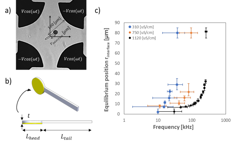
The chips are fabricated using standard photolithography and consist of either a quadrupolar with a gap of 200 and 500 for DEP (Fig. 1) and ROT (Fig. 2) characterization, respectively, as well as a ring electrode array with a gap of 200 between the electrodes for control purposes acting as an electrode geometry where no stable equilibrium can exist (Fig. 4). The electrolyte solution consists of dissolved KCl salt within DI water at different concentrations which is then introduced into a shallow chamber (height of 120 ) covering the electrode array along with the ‘lollipop’ particles. In order to reduce adsorption, the chamber is pretreated with 0.2% v/v of Tween 20 (Sigma). The electrodes are connected to a function generator, which we use to control the frequency and amplitude of the applied electric field. For the ROT setup we used a rotating electric field such that is has 90 degrees phase shift between the electrodes.
A complex particle can be potentially stagnant under the following modes: (1) at the center of the quad under nDEP response Voldman et al. (2001); (2) at stable equilibrium positions within the quad where the two counteracting DEP forces exactly cancel each other; (3) at the edge of the electrode under pDEP response. This has been verified for the ‘lollipop’ shaped particle where the DEP equilibrium (i.e. mode 2) positions were varied with frequency. Figure 1a shows such complex particle in stable equilibrium mode, when the frequency of the alternating current electric field is such that parts 1 and 2 of the particles (as defined in figure 1b) are experiencing DEP forces of comparable magnitude and opposite directions. In order to measure the stable equilibrium position of the particles, they were placed inside the quad while experiencing an electric field at a specific frequency. Figure 1c shows the average equilibrium position of 3-5 particles versus the frequency of the applied field. In order to assure that this is indeed a stable equilibrium position the particles were often shaken after which they have recovered their equilibrium position. In addition, frequencies were applied in different order to negate the existence of system hysteresis (see supplemental movie 1).
It was found that increasing the conductivity of the medium results in a wider range of these equilibrium frequency windows. In addition, we found that the frequencies at which the particle transitions from nDEP to stable equilibrium and from stable equilibrium to pDEP strongly depended on the solution conductivity and shifts to higher values with increasing solution conductivity. Whereas the dielectric (SU8) tail of the particle always exhibit nDEP behavior the metallic coated head of the particle switches from nDEP to pDEP behavior with increasing frequency at a transition frequency that corresponds to the RC time of the induced EDL. This can explain the shift of the above transitions observed for the complex particle as the RC frequency increases linearly with .
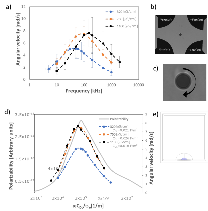
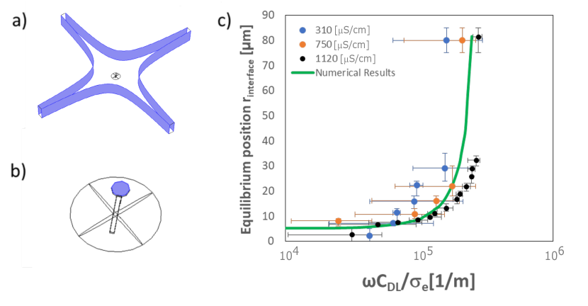
In order to match the experimental results to the numerical results with the angular frequency normalized by the conductivity and the specific capacitance of the electric double layer, , on the metallic coated disk we conducted several experiments of electro-rotating field (ROT) from which we extracted the . Due to the relatively high voltage applied on the particle, exceeding the thermal potential, the linear Debye-Huckel model for the capacitance is not applicable. Furthermore, there is always the ambiguity regarding the Stern layer capacitance which needs to be somehow resolved. Therefore, the value of the was experimentally extracted for each solution conductivity only for the coated disk particle without the tail section. A rotating electric field was applied in the 500 quadrupolar electrode array and the angular velocity of the gold coated disk was measured in different frequencies Park et al. (2017). After obtaining the ROT spectra for each conductivity (Fig. 2a) we used the as a fitting parameter in the normalized experimental curves to match the normalized angular velocities of the point of maximum angular velocity to that obtained in the numerical simulation (Fig. 2d). Following the extraction of the values the experimental results of the equilibrium position were then depicted using a normalized angular frequency and showed qualitative agreement with the numerical simulations (Fig. 3). For simplification, we have neglected the contribution of electro-convection on this electrostatic force balance as it is expected to be suppressed due to the shallowness of the microchamber height (120 ) (see supplemental movie 3).
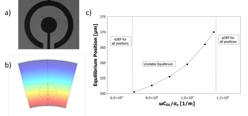
For a stable equilibrium to occur the non-uniform electric field must obey a certain spatial distribution (see supplemental figure S1). While the quadrupolar electrode array does satisfy the necessary conditions other electrode arrays such as the ring electrode shown in Fig. 4 does not. In accordance to the heuristic model described in the supplemental materials no such stable equilibrium was experimentally found in such a ring electrode setup. Instead, it has been found that the particles were either repelled from the inner electrode or attracted to it. The results of the simulations suggested that in the ring geometry exists a range of frequencies that the particle experiences an unstable equilibrium (Fig. 4c). Depending on the initial radial distance of the particle from the center of the array the response could be either pDEP or nDEP if it is smaller (i.e. ) or larger (i.e. ) than the equilibrium position, respectively (Fig. S1). Hence, due to the unstable equilibrium there are eventually two terminal positions of the particle, either at the inner electrode edge due to the dominance of pDEP or close to the edge of the outer ring electrode due to the dominance of nDEP. It is worth noting that since our system is not an ideal 2D geometry but is actually 3D, and hence there is an electric field intensification at the very edge of the outer ring electrode — the potential well of the nDEP is somewhat away from the edge of the outer ring electrode (see supplemental movie 4).
We have demonstrated that a complex engineered particle, where opposite DEP forces can occur at its different parts, exhibits a stable equilibrium within a frequency range. In addition, we found that the frequencies at which the particle transitions from nDEP to stable equilibrium and from stable equilibrium to pDEP strongly depended on the solution conductivity as expected. A quantitative comparison between the numerical results of the equilibrium position as function of frequency to the experimental results validates it and gives further information to the dependency of the equilibrium range with the solution conductivity. ROT spectra on the coated disk shows that indeed the metallic part of the particle undergoes transition from nDEP to pDEP as expected and the frequency of maximum angular velocity increases with increasing conductivity. This ability to control the equilibrium position of complex particles by simply changing the applied electric field frequency may open new opportunities for self-assembly, collective behavior and biosensing.
Acknowledgments
We wish to acknowledge the Technion Russel-Berrie Nanotechnology Institute (RBNI) and the Technion Micro-Nano Fabrication Unit (MNFU) for their technical support. PGS and AR acknowledge financial support by ERDF and Spanish Research Agency MCI under contract PGC2018-099217-B-I00.
References
- Jones (2001) T. B. Jones, Journal of Electrostatics 51, 290 (2001).
- Ben-Bassat et al. (2015) D. Ben-Bassat, A. Boymelgreen, and G. Yossifon, Journal of colloid and interface science 442, 154 (2015).
- Zhang and Chiao (2015) H. Zhang and M. Chiao, Journal of medical and biological engineering 35, 143 (2015).
- Morgan and Green (2003) H. Morgan and N. G. Green, AC Electrokinetics: colloids and nanoparticles. (Research Studies Press Ltd., 2003).
- Gagnon (2011) Z. R. Gagnon, Electrophoresis 32, 2466 (2011).
- Jones (2003) T. B. Jones, IEEE Engineering in medicine and Biology Magazine 22, 33 (2003).
- O’Konski (1960) C. T. O’Konski, The Journal of Physical Chemistry 64, 605 (1960).
- García-Sánchez et al. (2012) P. García-Sánchez, Y. Ren, J. J. Arcenegui, H. Morgan, and A. Ramos, Langmuir 28, 13861 (2012).
- Arcenegui et al. (2013) J. J. Arcenegui, P. García-Sánchez, H. Morgan, and A. Ramos, Physical Review E 88, 063018 (2013).
- Arcenegui et al. (2014) J. J. Arcenegui, P. García-Sánchez, H. Morgan, and A. Ramos, Physical Review E 89, 062306 (2014).
- Chen and Jiang (2016) Y.-L. Chen and H.-R. Jiang, Applied Physics Letters 109, 191605 (2016).
- Shuchat et al. (2019) S. Shuchat, S. Park, S. Kol, and G. Yossifon, Electrophoresis 40, 1606 (2019).
- Shields IV et al. (2018) C. W. Shields IV, K. Han, F. Ma, T. Miloh, G. Yossifon, and O. D. Velev, Advanced Functional Materials 28, 1803465 (2018).
- Kherzi and Pumera (2016) B. Kherzi and M. Pumera, Nanoscale 8, 17415 (2016).
- Han et al. (2018) K. Han, C. W. Shields IV, and O. D. Velev, Advanced Functional Materials 28, 1705953 (2018).
- Yan et al. (2016) J. Yan, M. Han, J. Zhang, C. Xu, E. Luijten, and S. Granick, Nature materials 15, 1095 (2016).
- Boymelgreen et al. (2016) A. Boymelgreen, G. Yossifon, and T. Miloh, Langmuir 32, 9540 (2016).
- Squires and Bazant (2006) T. Squires and M. Bazant, Journal of Fluid Mechanics 560, 65 (2006).
- Voldman et al. (2001) J. Voldman, R. A. Braff, M. Toner, M. L. Gray, and M. A. Schmidt, Biophysical Journal 80, 531 (2001).
- Park et al. (2017) S. Park, D. Capelin, G. Piriatinskiy, T. Lotan, and G. Yossifon, Electrophoresis 38, 1996 (2017).