Polar morphologies from first principles: PbTiO3 films on SrTiO3 substrates and the surface reconstruction
Abstract
Low dimensional structures comprised of ferroelectric (FE) PbTiO3 (PTO) and quantum paraelectric SrTiO3 (STO) are hosts to complex polarization textures such as polar waves, flux-closure domains and polar skyrmion phases. Density functional theory (DFT) simulations can provide insight into this order, but, are limited by the computational effort needed to simulate the thousands of required atoms. To relieve this issue, we use the novel multi-site support function (MSSF) method within DFT to reduce the solution time for the electronic groundstate whilst preserving high accuracy. Using MSSFs, we simulate thin PTO films on STO substrates with system sizes atoms. In the ultrathin limit, the polar wave texture with cylindrical chiral bubbles emerges as an intermediate phase between full flux closure domains and in-plane polarization. This is driven by an internal bias field born of the compositionally broken inversion symmetry in the [001] direction. Since the exact nature of this bias field depends sensitively on the film boundary conditions, this informs a new principle of design for manipulating chiral order on the nanoscale through the careful choice of substrate, surface termination or use of overlayers. Antiferrodistortive (AFD) order locally interacts with these polar textures giving rise to strong FE/AFD coupling at the PbO terminated surface driving a surface reconstruction. This offers another pathway for the local control of ferroelectricity.
I Introduction
With the advent of advanced deposition techniques Schlom et al. (2008); Willmott (2004) has come a revolution in the engineering of thin film perovskite oxides and layered heterostructures for a variety of applications in nanoelectronics. These advancements have propelled research into the great variety of physical phenomena such systems can exhibit. These include enhanced colossal magnetoresistance Kobayashi et al. (1998), high-temperature superconductivity Sleight et al. (1993), the formation of interfacial two-dimensional electron and hole gases (2DEG/HG) Hwang et al. (2012); Yin et al. (2015) and the emergence of negative capacitance Zubko et al. (2016). While these are becoming well-documented Dawber et al. (2005); Mannhart and Schlom (2010); Zubko et al. (2011), new emergent phenomena resulting from exotic electrical polarization textures, including polar waves, vortices and polar skyrmion phases Lu et al. (2018); Sichuga and Bellaiche (2011); Damodaran et al. (2017); Hong and Chen (2018); Du et al. (2019) are less well understood. The toroidal moment born from the chirality of these polar morphologies can give rise to strong electrotoroidic, pyrotoroidic and piezotoroidic effects Prosandeev et al. (2008); Chen et al. (2015); Damodaran et al. (2017) all of which show promise to be exploited in new low dimensional functional devices. It is the purpose of this work to investigate these polar morphologies in low dimensional ferroelectric (FE) PbTiO3 (PTO) on SrTiO3 (STO) substrates using state-of-the-art methods based on density functional theory (DFT) designed for demanding calculations with large numbers of atoms Nakata et al. (2020, 2014).
Further complex phenomena can arise by the interacting order parameters of the system. Notably, many perovskites (and heterostructures) are susceptible to both the antiferrodistortive (AFD) and FE distortions. In the bulk, these two modes were thought to suppress one another, although, recent evidence suggests that a cooperative regime may also exist Gu et al. (2018); Aschauer and Spaldin (2014). At surfaces and interfaces we see phase coexistence. For example, at the PbO terminated [001] surface of PTO, we observe the AFD c() surface reconstruction. This is characterised by strong antiphase rotations of the TiO6 octahedra about the [001] axis (or in Glazer’s notation Glazer (1972, 1975)) and is known to coexist with and mutually enhance in-plane ferroelectricity Munkholm et al. (2001); Bungaro and Rabe (2005); Sepliarsky et al. (2005). It is now popular to interface PTO with STO in the repeating (STOn/PTOn)N superlattice for alternating perovskite unit cells repeated times in a layered heterostructure. In the case of an ultrashort period (), hybrid-improper ferroelectricity can arise from the coupling of AFD and FE modes. Bousquet et al. (2008).
The (STOn/PTOn)N heterostructure continues to be studied from a theoretical perspective. Most frequently considered is full periodic boundary conditions with infinitely repeated layers. This has been studied with first principles DFT Aguado-Puente et al. (2011) where the focus has been on the interactions of FE and AFD instabilities in the monodomain configurations. More recently, however, polydomain configurations have been studied and ferroelectric flux-closure domains have been shown to be stable Aguado-Puente and Junquera (2012). Since these simulations are of the bulk superlattice, there can be no account for the surface reconstruction. Polydomain simulations of pure TiO2 terminated PTO films (which do not give rise to enhanced surface AFD modes Bungaro and Rabe (2005); Munkholm et al. (2001)) have been performed but neglect the STO substrate by instead choosing to adopt the fictitious free-standing film geometry Shimada et al. (2010). This work then cannot make any account for substrate/interface effects or the intrinsically broken inversion symmetry for epitaxially deposited films on substrates. To the author’s knowledge, there has been only a single DFT-based study treating both the surface and the STO substrate. This study probed the nature of the theoretically proposed 2DEG/HG pair Yin et al. (2015) where thicker films ( unit cells) of the FE monodomain out-of-plane configuration were considered as large depolarising fields are known to suppress this configuration in thinner films Junquera and Ghosez (2003). Multiple FE domains are considered a competing phase but no 2DEG/HG pair emerges as the resulting flux closure domains are an alternate mechanism for screening the depolarising field Aguado-Puente et al. (2015).
The polydomain configuration is challenging to simulate from the perspective of DFT. The difficulty arises from the increased number of atoms in the supercell as a result of treating a fixed domain period . If we are also to treat a finite thickness of film , the Kittel scaling law requires that the equilibrium too increases since Streiffer et al. (2002); Fong (2004). We must also account for a significant amount of substrate as the large ferroelectric polarization of PTO may be able polarise a few layers of STO. Finally, if we wish to include AFD modes in our simulations (like the ) surface reconstruction), the periodicity in the [010] direction must be doubled as to not frustrate the octahedral rotations. To include all of all of these effects, calculations with a supercell containing a few thousand atoms are needed rather than the few hundred that conventional planewave DFT is able to handle Bowler et al. (2006); Bowler and Miyazaki (2012). To overcome these limitations, some resort to alternative methods including phase fields, shell models, Monte Carlo and second principles Ghosez and Junquera (2006); García-Fernández et al. (2016); Chen (2002); Shafer et al. (2018); Damodaran et al. (2017); Sichuga and Bellaiche (2011); Chapman et al. (2017); Sepliarsky et al. (2006). Whilst these approaches each have their merits, they cannot universally serve as a replacement for full DFT. Most of these methods implicitly accept that full DFT offers superior accuracy since they either are or can be parameterised by the theory García-Fernández et al. (2016); Chapman et al. (2017); Sepliarsky et al. (2006). Further, all of these methods make no account (or little account García-Fernández et al. (2016)) for the electronic structure, limiting the ability of simulations to adapt to new chemical environments like at surfaces and interfaces with a substrate. In this work, we utilise a novel variation on full local orbital DFT which allows us to consider systems of a few thousand atoms whilst preserving high chemical accuracy Nakata et al. (2014).
We provide a full first principles study on ultrathin films of PTO down to a single PbO monolayer () up to 9 unit cells () where is the number of perovskite unit cells stacked in the [001] direction. We treat explicitly the STO substrate and the PbO termination invoking the c() surface reconstruction. As well as treating paralelectric films, we treat two monodomain configurations of the polarization ( [100] and [110]) and stripe domain patterns comprised of alternating [001] and [] domains. We do not consider monodomain polarization oriented in the out-of-plane directions ( [001] or [00]) since a previous work has shown this is suppressed by the depolarising field within our range of thicknesses (also verified to be true within our simulations). We characterise the competing energetics of the different film geometries as well detailing the resulting polar morphologies, interactions with the surface reconstruction and other structural features. This work is then organised as follows: section II.1 constitutes an overview of the multi-site support function method as applied in this study whilst Section II.2 presents finer details associated with the simulation method. Section II.3 details the treated film geometries for each thickness of film. In section III.1 we compare the competing energetics between each film geometry as a function of thickness. In section III.2, the local polarization fields of the various film geometries are discussed and in Section III.3, we detail the amplitudes of local AFD modes, including the surface reconstruction, its coupling with surface polarization and the asymmetrical rumpling of surface/interfacial Pb cations. We conclude this work in Section IV providing a summary of the findings of this investigation, commenting on the impact this work has on the field and suggesting new areas for which our novel method is applicable.
II Theoretical method
Simulations based on DFT have provided accurate first-principles descriptions of countless condensed matter and molecular systems since the 1970s. The method is centered upon the self-consistent calculation of the charge density for a system of interacting ions and electrons occupying independent Kohn-Sham Kohn and Sham (1965) orbitals. The ground-state total energy of the system is evaluated as a uniquely defined functional of this as detailed in the Hohenberg-Kohn theorem Hohenberg and Kohn (1964). This method would allow for exact calculations if it weren’t for the small electronic exchange and correlation terms for which the exact functional is unknown, thus, (increasingly accurate) approximations must be made. In this work, calculations were performed using the implementation of DFT present in the CONQUEST code Nakata et al. (2020); Bowler et al. (2020). This code is designed for large-scale, massively parallel simulations on thousands (even millions Bowler and Miyazaki (2010)) of atoms, utilizing the latest in high performance computing (HPC). While we now focus on the multi-site support functions used in this work (Section II.1), we refer the reader to Nakata et al. (2020); Bowler et al. (2006); Bowler and Miyazaki (2012) for further details on the CONQUEST methodology and to Bowler et al. (2020) for a recent (freely available) public release of the code.
II.1 Multi-site support functions
This section seeks to provide a convenient overview of the multi-site support function method (MSSF) method as implemented in CONQUEST Nakata et al. (2020); Bowler et al. (2020). For a more detailed discussion, the reader is referred to Nakata et al. (2014); Rayson and Briddon (2009) and references therein.
We begin by considering the Kohn-Sham equations in a non-orthogonal basis in terms of the Hamiltonian and overlap matrix elements and
| (1) |
for ionic sites , orbital indices , , eigenvalues and wavevector . Here, the Kohn-Sham eigenstates are written as a linear combination of support functions
| (2) |
for support function coefficients . A support function is a local orbital which we define to become zero at some cutoff radius (, ). It is then possible to represent these support functions in a compact, efficient basis of atomic-centered functions whose spatial cutoff leads to the onset of matrix sparsity (important to the mode of operation). How we choose to do so is paramount as this determines the accuracy and computational effort required for the calculation of the electronic groundstate. For accurate calculations we generally employ multiple- basis-sets Bowler et al. (2019); Baker et al. (2020); Soler et al. (2002). The most accurate evaluation of the support function coefficients here comes from the mapping of one to one support function and the subsequent diagonalisation of a large . This, however, comes with the burden of the greatest computational cost since this operation scales cubically with the total number of basis functions. Another choice is to make a basis set expansion of
| (3) |
where index is th atomic basis function on atomic site . The coefficients can be found through an optimisation method such as the conjugate gradients scheme. Another choice for equation 2 is to build a support function from all of the basis functions on atomic site . This is a simple extension of eq 3 where instead of having , spans all on site . While performing any of the previous two contractions does indeed reduce the number of required support functions, we are still unable to achieve a minimal representation due to atomic symmetry constraints Torralba et al. (2008).
To achieve this minimal representation, we use the multi-site contraction
| (4) |
where is an atomic site enclosed within a sphere of radius about target atom , inclusive of . As the coefficients now span a subspace of a local molecular orbital (MO), we are now relinquished from the atomic symmetry constraints. To find the optimal balance between efficiency and accuracy, we use the local filter diagonalisation method Rayson and Briddon (2009); Rayson (2010) to evaluate the coefficients. This requires the solution of a local eigenproblem in a subset enclosed by a sphere of radius () for each target atom.
| (5) |
For subspace eigenvalues , MO coefficients and where and are the local subsets of the system-wide Hamiltonian and overlap matrices respectively. By projecting onto a set of trial vectors , we obtain the contraction coefficients
| (6) |
Lastly, is mapped onto the corresponding position in the contraction coefficient vectors, whose elements are extracted for use in eq 4.
The MSSF method therefore introduces two new adjustable parameters to the DFT calculation; and . The former expands the space used for the local filter diagonalisation and the latter modifies the representation of . The accuracy of the contraction can be improved by increasing both of these subject to . In practice, convergence can be achieved for relatively modest values of both (1-2 lattice constants of the bulk). Using this method, high accuracy calculations with a few thousand atoms can feasibly be performed on most standard HPC systems. Structural relaxations of atoms (to a stringent force tolerance, as seen in this work) can be expected to take 1-2 weeks of wall-time on physical cores. Simulations of atoms may need physical cores to meet the memory requirements, dependant on the memory-per-node on the HPC system.
II.2 Simulation details
Within the MSSF mode of operation described in section II.1, we find that Å sufficiently converges relevant quantities (discussed in the supporting information). All simulations use the local density approximation (LDA) as parameterised by Ceperley, Alder, Perdew and Zunger Perdew and Zunger (1981); Ceperley and Alder (1980) to describe exchange and correlation effects. This functional has recently been shown to perform well against higher rung functionals for describing the properties of the perovskite oxides Zhang et al. (2017). Although both hybrid and meta-GGA functionals better predict the experimental structural properties, they still overestimate the bulk polarization of PTO. Since this is the primary order parameter of our system, LDA is a good choice as the magnitude of the overestimate is much less.
Optimised Vanderbilt norm-conserving pseudopotentials are used to replace core electrons. Hamann (2013); Vanderbilt (1990). We use the scalar-relativistic variety available in the PseudoDojo library (v0.4) van Setten et al. (2018). These are used as an input for the ONCVPSP code (v3.3.1) Hamann (2013). We then generate a double- plus double-polarization (DZDP) basis set of pseudo-atomic orbitals (PAOs) describing the Pb 5d 6s 6p 6dp, Sr 4s 4p 5s 4dp, Ti 3s 3p 4s 3d 4pp and the O 2s 2p 3dp orbitals respectively. Those orbitals superscripted with are polarization orbitals aimed at increasing the angular flexibility of the basis. Ti 3s, Ti 3p and Pb 5d orbitals are treated as semi-core states described only with a single . These PAOs are used to represent the support functions in section II.1. The PAO basis constructed using this set of pseudopotentials has been shown to provide high accuracy lattice constants, bulk moduli and electronic properties Bowler et al. (2019); Baker et al. (2020).
Momentum space integrals are performed on a non--centered uniform mesh as described by Monkhorst & Pack Monkhorst and Pack (1976) where are the number of perovskite unit cells included in the [100] and [010] directions of the supercell respectively. While many real-space integrals are performed using intuitive analytic operations Torralba et al. (2008), some are performed on a fine, regular integration grid with a plane-wave equivalent cutoff of 300 Ha. This yields the cubic lattice constants of PTO and STO ( and ) as 3.904Å and 3.874Å respectively. Further, the tetragonality (c/a) of FE PTO is obtained as 1.04 producing a spontaneous polarization of 79.02 as calculated with Resta’s method Resta (1999); Resta et al. (1993) within the modern theory of polarization. This method is equivalent to the Berry phase Berry (1984) formula of King-Smith and Vanderbilt King-Smith and Vanderbilt (1993) in the limit of large cells; we use 10 PTO unit cells in the direction of the FE distortion to achieve convergence. Each of the structures in section II.3 are fully relaxed (subject to constraints) with quenched molecular dynamics until the maximum absolute value of the force on every atom falls below eV/Å. Since our slabs feature asymmetric surface terminations, a small dipole moment can develop in the out-of-plane direction. This propagates to a spurious electric field across the supercell which we correct using the scheme of Bengtsson Bengtsson (1999).
II.3 Supercell configurations
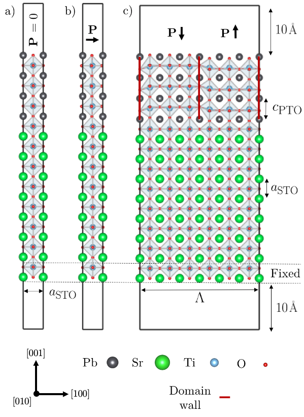
The film geometries considered in this work are displayed in Figure 1. Universal to all structures is a fixed amount of STO substrate. We find that 8/7 alternating SrO/TiO2 monolayers is sufficient to converge the relaxed ionic positions of the PTO films (demonstrated in the supporting information, in agreement with a similar classical study Sepliarsky et al. (2006)). An interfacial region exists between the first PbO layer and last SrO layer which we assign to belong to neither the film or substrate. The in-plane components of the supercells are held to integer multiples of . The two bottom-most monolayers of the substrate have their atomic positions fixed in structural relaxations. These measures ensure we are applying a realistic mechanical strain to the PTO film as well as simulating the effects of a semi-infinite substrate. To limit unfavorable interactions with images of the film in the [001] direction, we introduce a total of of vacuum. All supercells have the generalised dimensions {, , }. We simulate films of thickness 0, 1, 2, 3, 5, 7 and 9 formula units of PTO where a thickness of 0 corresponds to a single PbO monolayer. Films of unit cells were increased in steps of two unit cells such that the equilibrium domain period predicted by Kittel scaling could increase by an even integer number of unit cells (a requirement for domains to have an equal number of unit cells). This range of film thicknesss could encompass different energetically stable geometries including a transition between FE monodomain, polydomain and possible intermediate phases. It also spans low dimensional films with strong interface coupling with such effects decreasing with increased thickness.
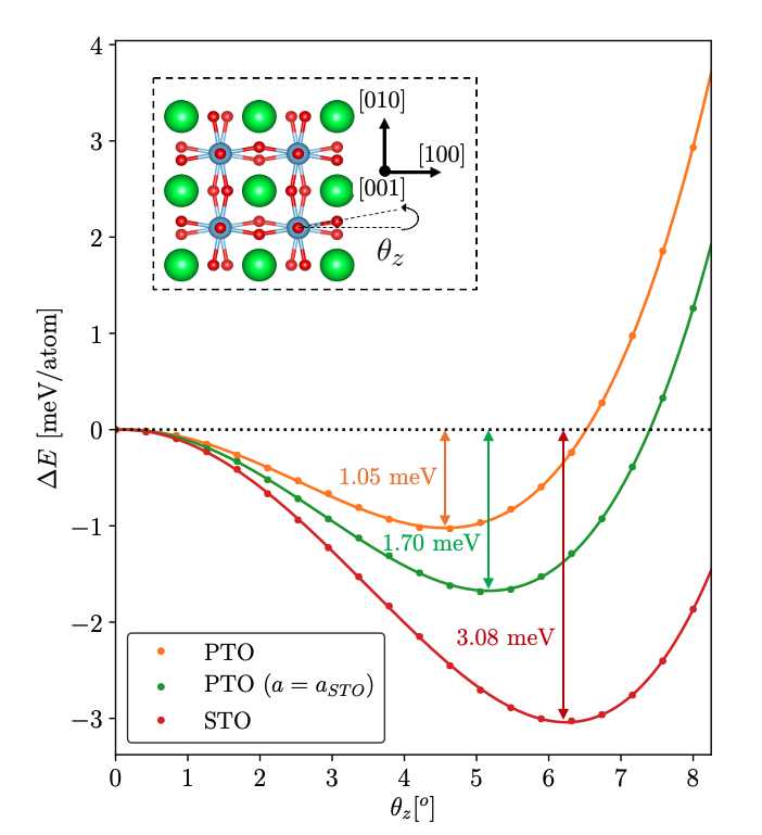
We choose to treat the following supercell configurations with and without the influence of AFD modes. Note also that structures treated without these modes do not show the surface reconstruction. To do so, we must set and have set to multiples of 2. The important AFD distortions for both STO and PTO are the zone-boundary and modes. The former is equivalent to a Glazer tilt system Glazer (1972, 1975) while the latter is . The former has been found previously to be the most energetically favorable so we do not treat the mode Lebedev (2009). The mode can be defined with a single rotation angle as shown in the inset of Figure 2. We find that the angles and (Figure 2) define minima in the energy of the cubic supercells of STO and PTO respectively. Since simulations are performed with the in-plane lattice constants of STO, we initialise supercells with the optimal strained PTO rotation angle as found in the tetragonal supercell. These results indicate that strains of in PTO are able to both increase the optimal and increase the depth of the energy minima. These angles overestimate what is seen in experiment. For STO, Lytle (1964) while AFD modes are not observed in the PTO bulk. Calculations using hybrid functionals have been able improve this angle for STO ( Heifets et al. (2006)) but are not used in this study in part because of the computational cost but also due to the aforementioned overestimate in the bulk polarization of PTO.
II.3.1 Paraelectric
First we consider films of the high symmetry, paraelectric, non-polar variety (Figure 1a). These supercells are initialised by PTO formula units with the high symmetry cubic fractional atomic positions and optimal cubic out-of-plane lattice constant Å. Although spatial inversion symmetry is intrinsically broken by the composition of our supercells, we constrain atomic relaxations of these films to the lowest symmetry space group () carefully preventing any cation-anion counter motion. This allows for the most degrees of freedom in relaxations without incurring any intrinsic ferroelectric polarization. It is the purpose of these films to provide a baseline for the relative stability of polar phases.
II.3.2 Monodomain in-plane ferroelectric
In this supercell, we allow monodomain ferroelectric polarization to develop in the [100] and [110] directions (Figure 1b). PTO formula units retain the same as the paraelectric case but atomic positions now correspond to the mode of the primitive cubic PTO unit cell orientated in the [100] direction. This induces a ferroelectric polarization of 56.9 in the infinite bulk as calculated with the method described in Section II.2. To create [110] polarization, we simply displace the metal cations along the [110] direction and displace Oxygen anions along the [] direction proportional to the magnitude of the bulk mode. During structural relaxation, we apply symmetry constraints to prevent the development of out-of-plane polarization Bungaro and Rabe (2005) although the non-trivial depolarising field that would result naturally suppresses it.
II.3.3 Polydomain ferroelectric
Here we consider films intialised with a striped domain structure consisting of alternating regions of PTO polarised in the [001] and [00] directions which we will from this point onwards refer to as up and down domains respectively (Figure 1c). Up and down domains are equal in size () and together form a full domain period . Equivalently, . Domain walls are chosen to be centered on the PbO plane. This choice, however, is arbitrary as the energy difference between this and the TiO2 centering is found to be meV per unit cell Shimada et al. (2010). This is (slightly) beyond the resolution of our calculations, a fact noted in a comparable study. Aguado-Puente and Junquera (2012).
It is found that there is a minimum thickness of film for this type of ferroelectricity to occur. Theoretical results of the free standing PTO film have shown that the polydomain ferroelectric film is lower in energy than the paraelectric configuration Shimada et al. (2010) but make no account of possible monodomain in-plane orientations for the polarization. In experiments conducted with an STO substrate Fong (2004) it was found that that the polydomain configuration was only observed above 3 unit cells in thickness (in the temperature range of 311-644K). We also confirm that no out-of-plane component of remains after structural relaxation of polydomain and 2 films (). We then only consider this configuration for those film thicknesses . PTO unit cells are initialised with the strained FE unit cell. When the in-plane constants are constrained to , this results in Å and a slightly enhanced polarization of 80.07 .
An accurate account for the polydomain structure requires us to work at the equilibrium domain period. To avoid the need to manually find this domain period for each thickness (which would require us to simulate several domain periods for each film thickness), we use knowledge from previous experimental and theoretical data. In particular, we find that both theory and experiment agree upon when Shimada et al. (2010); Fong (2004). We use X-ray diffraction data Streiffer et al. (2002) for the remaining film thicknesses. We choose the nearest even number of unit cells (to preserve the periodicity of the AFD rotation pattern) corresponding to the experimental domain periods. We then have for the films, domain periods of unit cells respectively. Films of this configuration are free from constraints during structural relaxation.
In a study of monodomain out-of-plane polarization, it was found that [00] (towards the STO substrate) becomes more polar than [001] (towards the vacuum). For polydomain films, this could mean that up domains are less polar than down domains. This would result in a small net dipole moment in the [00] direction (and a spurious electric field) developing during structural relaxation which is corrected for using the scheme described in Section II.2.
III Results
III.1 Competing phases
The film geometries considered have energetics which evolve as a function of film thickness. Figure 3 displays this behaviour indicating the favorability of different phases. We measure this favorability as the energy difference between the geometry of film in question and the paraelectric film. We choose to measure in meV/atom since the (more common) definition of meV/formula unit would vary with film thickness. This is because as the film thickness increases, the Pb/Sr fraction (upper axis of Figure 3) increases as an artefact of a fixed amount of STO substrate. As a result, we expect to see a component energy lowering from ferroelectric phases as we increase since the energy of PTO is lowered with the onset of ferroelectricity (by 9.58 meV/atom in the bulk). We then expect to observe a rise in energy for purely AFD phases since the the fraction of STO, favoring AFD modes, has decreased. The energetics of film thickness = 0 are not present on Figure 3 since no ferroelectric phase was stable. Adding AFD rotations does however lower the energy compared to the paraelectric film by an amount similar to = 1.
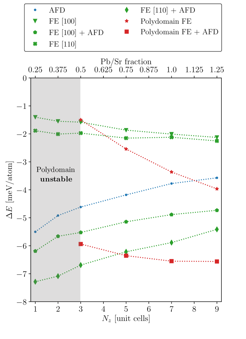
Considering first the monodomain in-plane ferroelectric films, Figure 3 shows that the favored axis for the polarization is always [110] as was shown in a DFT study of the free standing film under compressive strain Umeno et al. (2006). This is true with and without the influence of AFD modes. This favorable direction seems to diminish with film thickness becoming almost degenerate with [100] polarization at for the films not influenced by AFD modes. When AFD modes are taken into account, the degree of favorability for [110] polarization (compared with [100]) almost doubles showing that [110] polarization is far more compatible with rotations. We suggest that [110] polarization is more favorable than [100] since is stunted by the epitaxial strain. An increased distortion along the longer diagonal axis of the supercell (of length ) when compared with a distortion parallel to one of the pseudocubic axes (of length ) relieves this stunting. We can also deduce whether coupling between AFD and FE modes is cooperative or competitive. The sum of for the FE [100] curve and the AFD curve is always lower than the combined FE [100] + AFD curve. This indicates that the the coupling is competitive with AFD modes suppressing FE ones and vice versa as is usually true for bulk modes. When making the same comparison for [110] polarization (which is not observed in the bulk), however, it very closely mirrors the combined FE [110] + AFD curve. This suggests that FE and AFD modes are at worst independent of one another, but, for or 3 are mildly cooperative, with the FE [110] + AFD curve being lower in energy than the sum by meV/atom (close to the resolution of the simulation).
Remarkably, the polydomain configuration is not universally the ground state. Monodomain [110] polarization is the lowest in energy until a film thickness of 4-5 unit cells. This is close to the experimental observation of a polydomain structure at a thickness of 3 unit cells Fong (2004) with the difference perhaps being an artefact of finite temperature in experiment. We note also that these results agree with the theoretical findings of Shimada Shimada et al. (2010) in that at a thickness of 3 unit cells, the polydomain configuration is lower in energy the the paraelectric film. In this work, however, while the energy is lowered by this geometry, monodomain in-plane [110] polarization is favored at this depth. It is important to note that this work treats the PbO termination whilst the work of Shimada treats the TiO2 termination. As we discuss later (in Section III.2), the polydomain film does not condense the flux-closure domain morphology but instead shows a polar wave (Figure 5b). This clearly will have an impact on the energetics. Comparing the energy of the combined polydomain FE + AFD curve with the sum of the polydomain FE and AFD curves, we find that the latter is always lower in energy (a gap which widens with increasing film thickness). This suggests that that polydomain FE competes with AFD modes. This effect is not as drastic as the competition between FE modes and monodomain [100] polarization however.
III.2 Polarization morphologies
In this section we analyse and compare the polar morphologies of the different films using a metric known as the local polarization, . We define per 5-atom perovskite unit cell using a linear relationship between the local mode and the Born effective charges in the manner first suggested by Resta Resta et al. (1993) (now used in similar works Meyer and Vanderbilt (2002); Aguado-Puente and Junquera (2012)). We discuss this method in more detail in the supporting information. A vector field of this quantity has been calculated for all polar structures presented in Figure 4 and 5.
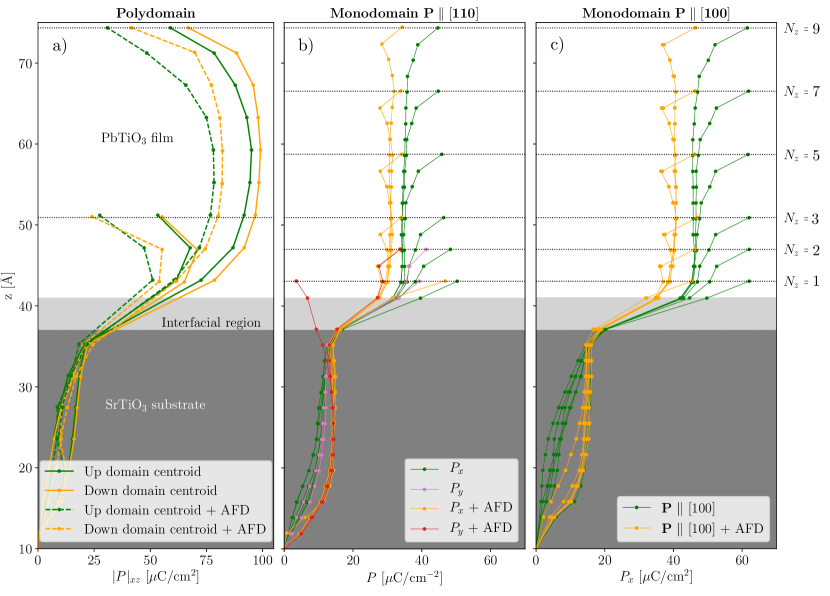
In Figure 4a we show the Ti-centered local polarization along the up and down domain centroids. The domain centroid here is a string of Ti centered unit cells in the vertical direction located at the centre of a domain. It is at the down domain centroid that the maximal local polarization can be found, buried in the upper third of the PTO film. Indeed, there is a discrepancy in polarization between the up and down domains throughout the entire film, leading to a small net dipole moment in the [00] direction. This effect can be explained by the compositionally broken inversion symmetry present in even the highest symmetry films (the relaxed geometry described in Section II.3.1). The result is that [00] is favored by a built-in bias field directed towards the substrate. While we find that this field is local to the first few PTO surface monolayers, we suggest that the enhanced local [00] modes at the surface spread to the rest of the domain due to a finite correlation length associated with the polar atomic displacements Glinchuk et al. (2010). This leads to an indentation of the substrate (as seen in figure 7) creating extra volume for the down domains and enhanced local tetragonality which mutually couples with the polarisation. The opposite argument is also true for the local [001] modes within the up domain whereby the internal bias field is now depolarising. We predict that such a disparity between the up and down domains will diminish with increasing film thickness, tending to zero as the film thickness becomes much larger than the correlation length of the enhanced local polar modes. The scenario explained above is analogous to the observation of built-in bias fields present three component or tricolor superlattices Sai et al. (2000); Warusawithana et al. (2003) where our third component is the vacuum region
.
We find that the maximal polarization increases with film thickness for the polydomain films. Although we only display and in Figure 4a, the rise is gradual when considering the maximal polarization of the and films also. This reflects the results of synchrotron X-ray diffraction Fong (2004) whereby satellite peak intensity (indicative of domain polarization) is an increasing function of film thickness. Such a phenomenon is likely a result of decreasing depolarising field strength with increasing film thickness as is observed for thicker [001] films Lichtensteiger et al. (2005). It is notable that by , this maximal polarization (for the case without AFD modes) exceeds the strained PTO bulk figure by 26%. The same enhancement is not seen for the which suffers a 12% reduction. It can be seen for all film geometries that the influence of AFD modes tends to reduce the polarization in the film. Figure 4a shows that allowing for AFD modes produces a local polarization reduction of 15 for all films. This reduction, however, becomes more severe as we reach the surface where we suggest that the enhanced local rotational modes at the surface reconstruction compete strongly with the polarization.
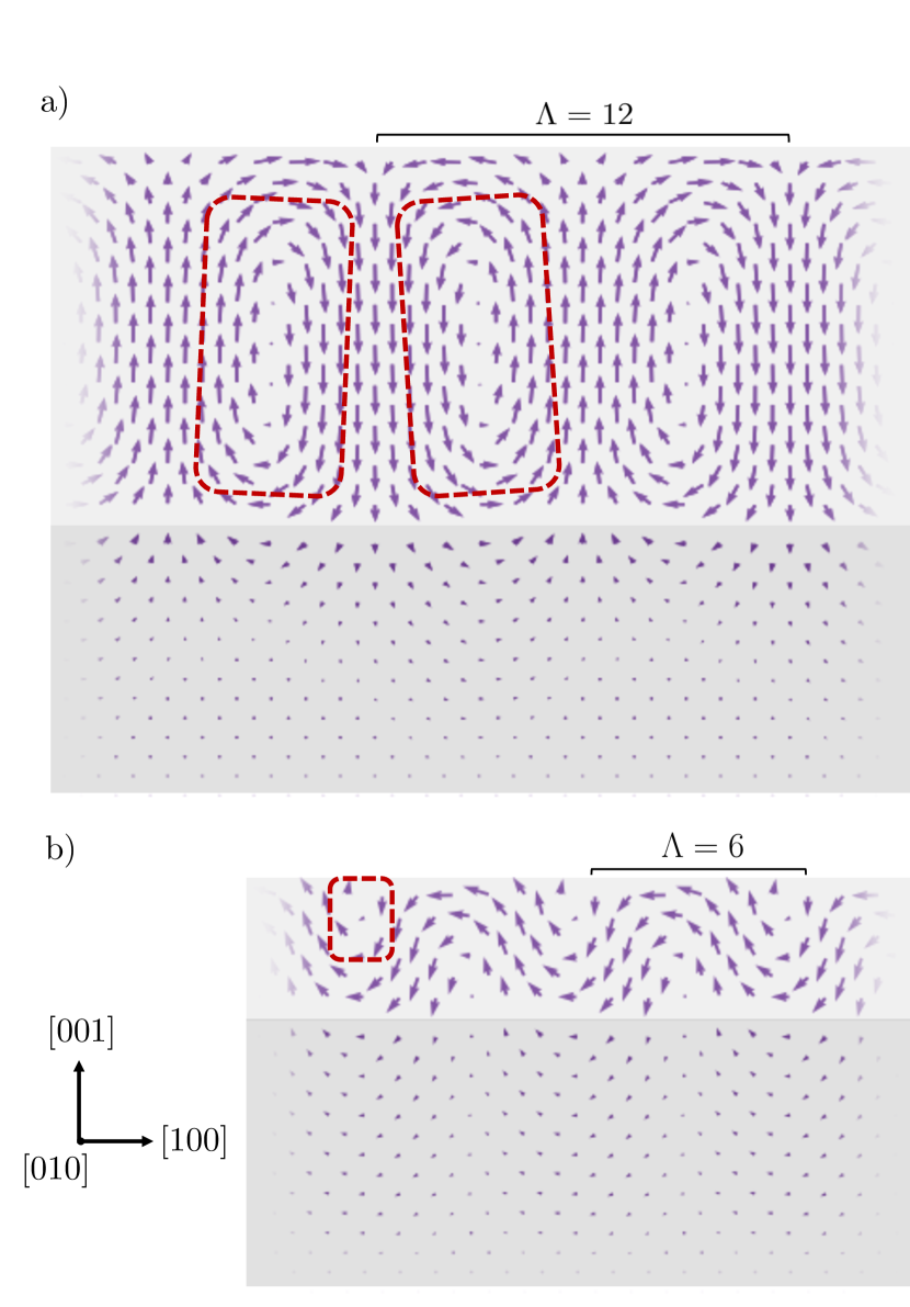
The majority of the relaxed polydomain structures, as seen in similar works, form the flux closure morphology (Figure 5a). That is, the local polarization gradually rotates through 180∘ across the domain wall at the top of the film and rotates through -180∘ at the bottom as a mechanism for screening the depolarising field. The result is counter-tilting vortex-like domain walls (Figure 5a, red areas), with a small vertical area for polarization at the vortex center. This domain morphology forms fully for the films with and without the influence of AFD modes. We note that whilst these domain structures share similarities with other works, they do have some key differences. The vortex cores are not located centrally (in the z-direction) in the film. They are instead shifted towards the substrate. We also see that at the surface, flux is closed more abruptly than at the interface with the substrate. At the interface, the polarization penetrates ( unit cells) into the substrate helping to close the flux. Together with the previously mentioned tendency for a stronger polarization in the [00] direction, this makes for a more asymmetrical morphology than those observed in the superlattice or free standing film arrangement Shimada et al. (2010); Aguado-Puente and Junquera (2012). In contrast to the work of Shimada Shimada et al. (2010), the film does not appear to form complete a flux closure domain structure. Examining Figure 5b we see that the flux does not fully close at the interface with STO. Instead, the polar morphology is S-like or wave-like, in this case orientated in the [00] direction giving the film a net in-plane macroscopic polarization. We deduce that at the surface, the flux does close by analysing the displacements of the terminating PbO layer (whose polarization vectors are not calculable with our method as explained in the supporting information). This gives rise to small cylindrical vortices near the surface which are sometimes known as cylindrical chiral bubbles (Figure 5b, red area) Lu et al. (2018); Sichuga and Bellaiche (2011).
Such an instability has been predicted as an intermediate phase in phase field simulations under applied electric fields in the superlattice arrangement Damodaran et al. (2017) as well as at zero field in high-angle annular dark field (HAADF) images Lu et al. (2018). This polar topology is also observed in thin PZT films as predicted with Monte-Carlo simulations of a first principles-based Hamiltonian Sichuga and Bellaiche (2011). Although such a polar topology has not yet been observed in thin PTO films, we note that previous XRD studies do not explicitly rule out the coupling to the characteristic in-plane wavevectors for the film Stephenson et al. (2003); Streiffer et al. (2002); Fong (2004). In this work, the polar-wave morphology appears as an intermediate phase between full flux-closure domains and in-plane polarization like in reference Damodaran et al. (2017) but in the absence of an applied field. This is replaced by the built-in bias field emergent from the compositionally broken inversion symmetry. Since this bias field is directed to suppress up domains but enhance down domains, up domains now have an increased critical thicknesses for the absolute suppression of out-of-plane polarization compared to down domains. We suggest that at , we are below this critical thickness for up domains (where in-plane FE modes are now favored) but still above it in down domains. The resulting polar wave texture is then emergent from the closing of flux between [00] and [00] (although [100] is equally favored) domains as shown in figure 5b. This finding suggests that control over polar morphologies can be achieved in ultrathin films by careful engineering of the boundary conditions. Specifically, we suggest that the built-in bias field can be manipulated through the choice of substrate, film surface termination or use of overlayers. This principle of design offers a promising avenue for the manipulation of chiral order in low-dimensional devices operating through the control of toroidal moments.
Figure 4b and 4c show the polarization profiles for the films initialised with uniform polarization oriented in the [110] and [100] directions respectively. For the former, we find that for most cases, (hence remains aligned along [110]) apart from the thinnest and 2 films. in particular, when coupled with AFD modes, (red line) polarization rotates strongly to be mostly polarised in [001]. For both [110] and [100] polarised films, we see that these films become polar as we cross the STO/PTO interface, quickly adopting a bulk like value. Then, for films without AFD modes, we see a polar enhancement near the surface. For those with AFD modes, we see a polar reduction followed by enhancement near the surface contrasting with the strong reduction for the polydomain films. Computing the norm of the polarization for the [110] and [100] films in the bulk-like region shows us that the [110] films have a polarization slightly enhanced (+2) compared to just [100] polarization. What is notable for the monodomain films is that (past a thickness of two unit cells at least) there is no trend for the behaviour of the local polarization for increasing film thickness. Each film shows the same bulk-like polarization then the same surface reduction or enhancement.
III.3 The p() surface reconstruction
.
An analysis of the competition between local FE and AFD modes can provide valuable insight into the design of new low dimensional devices whereby FE and AFD modes can be tuned to enhance their functional properties. In this section, we analyse the interaction of FE and AFD modes with a focus on strong coupling within the reconstructed surface layers of the PbO terminated films.
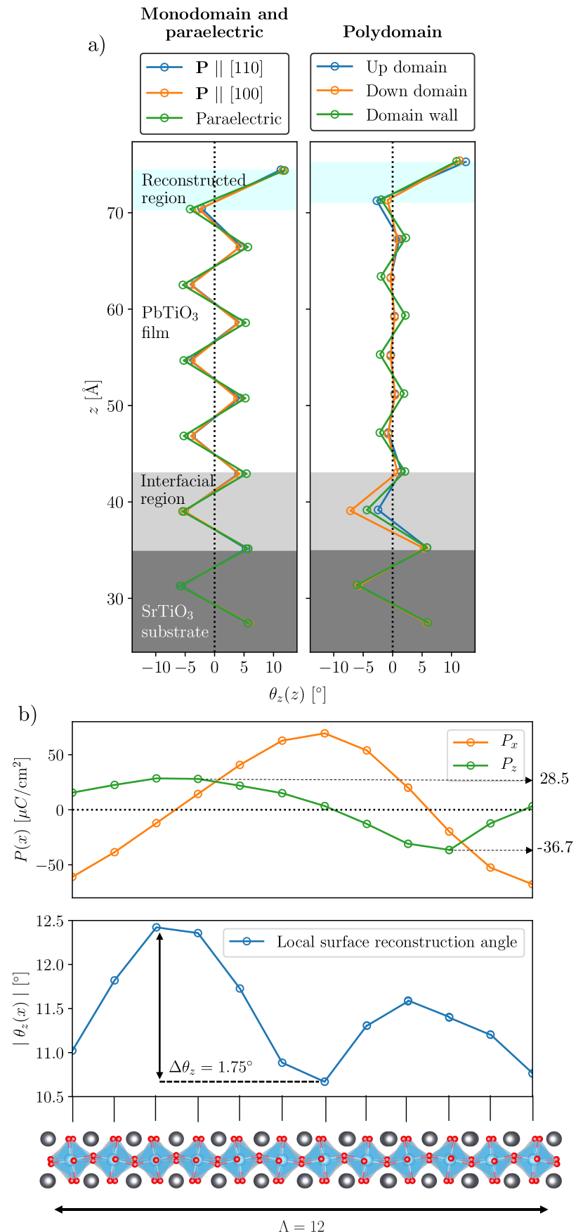
Figure 6 shows the local evolution of the octahedral rotation angle along the [001] direction (Figure 6a) and across a domain period in the [100] direction (Figure 6b) for the () film. The rotational behaviour in Figure 6a (left) is similar to the behaviour reported by Bungaro Bungaro and Rabe (2005) whereby the reconstructed area couples cooperatively with in-plane [100] polarization. We show that this also true for [110] (polarization is locally enhanced at the surface as shown by Figure 4b and 4c) with the rotation pattern being almost indistinguishable from the [100] polar film. We note that whilst this mutual AFD/FE enhancement is active at the surface, for the rest of the film, AFD/FE modes are mutually reduced when compared to the paraelectric structure and the bulk. The trend for the polydomain films (Figure 6a, right) is more complex. Rotations are almost completely quenched (reduced to ) at the up and down domain centroids compared to the domain wall (apart from the reconstructed region). We suggest that this occurs since the maximal polarisation at the centroids outcompetes AFD modes. We see similar behaviour for all for the effects listed above, even for the strength of the reconstruction angle. This is remarkably resistant to finite size effects, even at a single PbO monolayer (), persists at around despite the change in chemical environment for the surface TiO6 octahedra.
Figure 6b shows a coupling between local polarization at the surface (upper) and the surface reconstruction angle (lower). Across a domain period , we see that modulates by . peaks close to which is remarkable since this is precisely the opposite behaviour to the monodomain in-plane films where FE and AFD mutually support one another. Since and are radians out of phase with each other in the surface layer, it can also be said that the peaks in coincide with extrema in . We see also the the magnitude of has an impact on the height of the peaks in . That is, since the down domains are more polar than the up domains, the larger down polarization in the surface layer reduces the peak and vice versa for the for the smaller polarization in the up domain. We note that such AFD/FE couplings are different to those found in a recent shell model study of the free standing film Chapman et al. (2017). In this study, the symmetrical [001] boundary conditions for the film modulate over instead. We also note that whilst the strongest octahedral rotations are about the [001] axis, we also see smaller rotations of 2-3∘ about the [100] axis in the surface reconstruction. In addition to this, at the surface of the polar wave film for , we observe rotations about all three pseudocubic axes in the surface reconstruction. The strongest rotations are still about the [001] axis however.
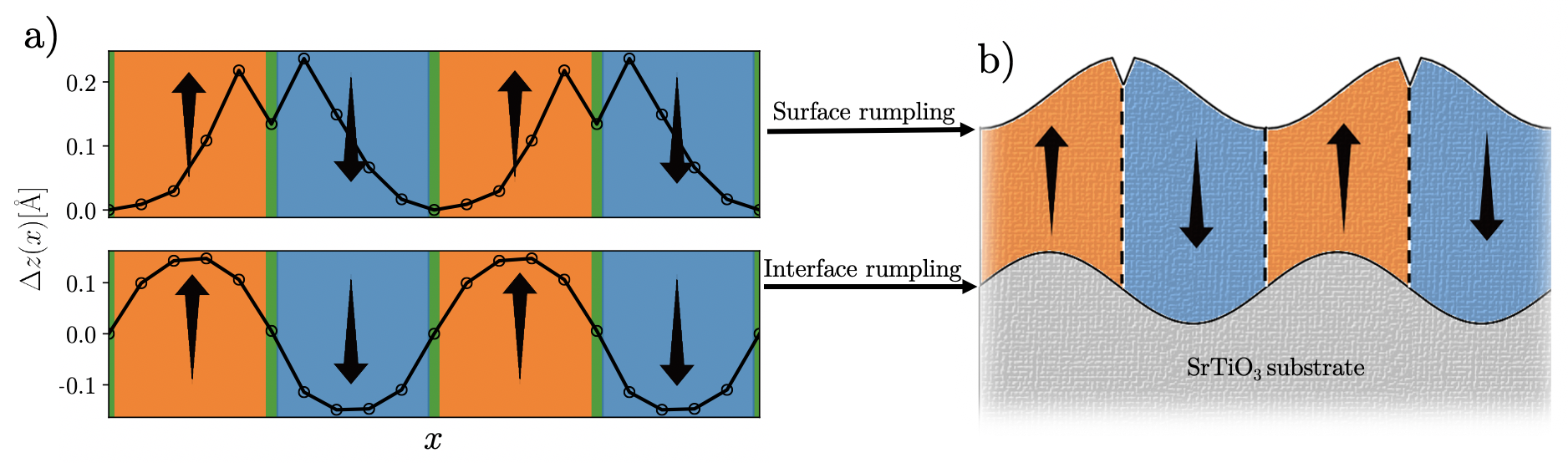
The broken inversion symmetry leads to further structural effects for the polydomain films. We can measure the distortion of the films in the vertical direction by considering the Pb displacements in the terminating PbO layer with the vaccuum and at the STO interface. 7 shows an exemplar calculation for the () film. The other film thicknesses all resemble the behaviour of this film. With the exception of a small dip in at the domain wall for the surface rumpling (a mechanism to reduce the domain wall formation energy), we see that interface and surface rumpling behave spatially like two sinusoids radians out-of-phase with one-another, reflected about the [100] direction. This is in contrast to the PTO/STO superlattice configuration Aguado-Puente and Junquera (2012) where the intact inversion symmetry preserves symmetrical rumpling (in-phase sinusoids). Due to the periodicity of octahedral rotations and Pb cation surface rumpling in the [001] direction, it is clear that for the polydomain films we must reconsider the labelling of the surface reconstruction. For monodomain and paraelectric films, the Wood’s notation Prutton (1994) of remains correct but an analysis of the symmetry for the the polydomain case reveals this must alter to become . We suggest that these fine FE/AFD interactions could now be observable in experiment thanks to recent advances in integrated differential phase contrast (iDPC) imaging Sun et al. (2019). In contrast to HAADF, iDPC images yield the positions of the metal cations and oxygen anions resolved at a subunit cell level Sun et al. (2019). This allows for the direct measurement of local FE and AFD modes offering an exciting new avenue for direct comparison with atomistic results.
IV Conclusions
We have used large-scale DFT calculations to simulate the energetics, interaction with AFD modes and other structural features for various polar morphologies present in thin PTO films on STO substrates. Our method is successful in providing accurate first principles results for systems comprised of a few thousand atoms, well beyond what is feasible with traditional plane-wave based methods, venturing towards systems sizes usually simulated with Monte Carlo or phase field techniques. This method has allowed for the explicit simulation of the STO substrate, multiple ferroelectric domains and doubled periodicity in the [010] direction used include AFD modes and the surface reconstruction. This has ensured that our simulations represent realistic experimental conditions when compared to previous works which neglect one or more of these features. Such simulations can be performed on standard HPC systems with high accuracy calculations of atoms becoming feasible using physical cores.
We have demonstrated the stability of the polydomain film geometry compared to monodomain phases. We have found that the polydomain case becomes more energetically favorable between 4-5 unit cells in thickness, close to the experimental observation at 3 unit cells. We find that the general effect of including AFD modes is to lower the energy significantly (in most cases more than the FE distortion) and to suppress the amplitudes of local polar modes (apart from at the surface of monodomain in-plane FE films, where they are mutually cooperative).
We show that polydomain films display the flux-closure domain morphology for and 9 whilst the film shows the similar polar wave morphology with cylindrical chiral bubbles as an intermediate phase between full flux closure domains and in-plane ferroelectricity. We find that local polarization is enhanced at the domain centroids when compared to PTO bulk; a trend which increases as a function of . Most notably, down domains feature enhanced local polar modes promoted by the internal bias field born of the compositionally broken inversion symmetry. Equally, this bias field acts to depolarise up domains leading to different critical thicknesses for the total suppression of out-of-plane ferroelectricity for the two domains. Since these critical thicknesses are the outcome of the strength and direction of the bias field, engineering this with a careful choice of substrate, surface termination or overlayers allows for control over polar textures at the nanoscale. This finding is especially important for next-generation functional devices reliant upon the control of toroidal order.
There are consequences also for the periodicity of the AFD surface reconstruction. While we find that the reconstruction for the monodomain in-plane FE and paraelectric films is , we find that coupling between surface polarization and AFD modes in the polydomain geometry modifies this. In addition to surface rumpling of Pb cations, the surface reconstruction angle modulates up to 1.75∘ across a domain period . We then suggest that for the polydomain films, the correct label for the AFD surface reconstruction is in Wood’s notation. This provides direct evidence that the strength of AFD modes can be locally controlled by the strength of FE modes and vice versa. Such knowledge could motivate new principles of design in low dimensional functional devices whereby FE and AFD modes are locally tuned by their interactions.
We suggest that the MSSF method implemented within the CONQUEST code can now be used to solve a plethora of problems within the perovskite oxides. This could include the simulating other potentially possible polar morphologies in the PTO/STO system such as skyrmion phases Hong and Chen (2018) and disclinations Damodaran et al. (2017). Since our method is general, we can extend to other problems in the perovskite oxides (and beyond) such as realistic defect concentrations and highly disordered configurations the popular solid solution families ABxC1-xO3, ABOCDO3 where DFT methods used to circumvent the need for large supercell calculations fail in the reproduction of local structural distortions Baker and Bowler (2019).
Acknowledgements
We are grateful for computational support from the UK Materials and Molecular Modelling Hub, which is partially funded by EPSRC (EP/P020194), for which access was obtained via the UKCP consortium and funded by EPSRC Grant Ref. No. EP/P022561/1. This work also used the ARCHER UK National Supercomputing Service funded by the UKCP consortium EPSRC Grant Ref. No. EP/P022561/1. We are also thankful for the oversight of Pavlo Zubko and Marios Hadjimichael in reviewing this manuscript and thank Pablo Aguado-Puente for his guidance in the preparation of local polarization vector fields.
References
- Schlom et al. (2008) D. G. Schlom, L.-Q. Chen, X. Pan, A. Schmehl, and M. A. Zurbuchen, J. Am. Ceram. Soc. 91, 2429 (2008).
- Willmott (2004) P. Willmott, Prog. Surf. Sci. 76, 163 (2004).
- Kobayashi et al. (1998) K.-I. Kobayashi, T. Kimura, H. Sawada, K. Terakura, and Y. Tokura, Nature 395, 677 (1998).
- Sleight et al. (1993) A. W. Sleight, J. L. Gillson, and P. E. Bierstedt, in Ten Years of Superconductivity: 1980–1990 (Springer Netherlands, 1993) pp. 257–258.
- Hwang et al. (2012) H. Y. Hwang, Y. Iwasa, M. Kawasaki, B. Keimer, N. Nagaosa, and Y. Tokura, Nature Mat. 11, 103 (2012).
- Yin et al. (2015) B. Yin, P. Aguado-Puente, S. Qu, and E. Artacho, Phys. Rev. B 92, 115406 (2015).
- Zubko et al. (2016) P. Zubko, J. C. Wojdeł, M. Hadjimichael, S. Fernandez-Pena, A. Sené, I. Luk’yanchuk, J.-M. Triscone, and J. Íñiguez, Nature 534, 524 (2016).
- Dawber et al. (2005) M. Dawber, K. M. Rabe, and J. F. Scott, Rev. Mod. Phys. 77, 1083 (2005).
- Mannhart and Schlom (2010) J. Mannhart and D. G. Schlom, Science 327, 1607 (2010).
- Zubko et al. (2011) P. Zubko, S. Gariglio, M. Gabay, P. Ghosez, and J.-M. Triscone, Annu. Rev. Condens. Matter Phys. 2, 141 (2011).
- Lu et al. (2018) L. Lu, Y. Nahas, M. Liu, H. Du, Z. Jiang, S. Ren, D. Wang, L. Jin, S. Prokhorenko, C.-L. Jia, and L. Bellaiche, Phys. Rev. Lett. 120, 177601 (2018).
- Sichuga and Bellaiche (2011) D. Sichuga and L. Bellaiche, Phys. Rev. Lett. 106, 196102 (2011).
- Damodaran et al. (2017) A. R. Damodaran, J. D. Clarkson, Z. Hong, H. Liu, A. K. Yadav, C. T. Nelson, S.-L. Hsu, M. R. McCarter, K.-D. Park, V. Kravtsov, A. Farhan, et al., Nat. Mater. 16, 1003 (2017).
- Hong and Chen (2018) Z. Hong and L.-Q. Chen, Acta Mater. 152, 155 (2018).
- Du et al. (2019) K. Du, M. Zhang, C. Dai, Z. N. Zhou, Y. W. Xie, Z. H. Ren, H. Tian, L. Q. Chen, G. V. Tendeloo, and Z. Zhang, Nat. Commun. 10, 4864 (2019).
- Prosandeev et al. (2008) S. Prosandeev, I. Ponomareva, I. Naumov, I. Kornev, and L. Bellaiche, J. Phys. Condens. Matter 20, 193201 (2008).
- Chen et al. (2015) W. J. Chen, Y. Zheng, and B. Wang, Sci. Rep. 5, 11165 (2015).
- Nakata et al. (2020) A. Nakata, J. S. Baker, S. Y. Mujahed, J. T. L. Poulton, S. Arapan, J. Lin, Z. Raza, S. Yadav, L. Truflandier, T. Miyazaki, and D. R. Bowler, J. Chem. Phys. 152, 164112 (2020).
- Nakata et al. (2014) A. Nakata, D. R. Bowler, and T. Miyazaki, J. Chem. Theory Comput. 10, 4813 (2014).
- Gu et al. (2018) T. Gu, T. Scarbrough, Y. Yang, J. Íñiguez, L. Bellaiche, and H. Xiang, Phys. Rev. Lett. 120, 97602 (2018).
- Aschauer and Spaldin (2014) U. Aschauer and N. A. Spaldin, J. Phys. Condens. Matter 26, 122203 (2014).
- Glazer (1972) A. M. Glazer, Acta Crystallogr. B 28, 3384 (1972).
- Glazer (1975) A. M. Glazer, Acta Crystallogr. A 31, 756 (1975).
- Munkholm et al. (2001) A. Munkholm, S. K. Streiffer, M. V. R. Murty, J. A. Eastman, C. Thompson, O. Auciello, L. Thompson, J. F. Moore, and G. B. Stephenson, Phys. Rev. Lett. 88, 016101 (2001).
- Bungaro and Rabe (2005) C. Bungaro and K. M. Rabe, Phys. Rev. B 71, 035420 (2005).
- Sepliarsky et al. (2005) M. Sepliarsky, M. G. Stachiotti, and R. L. Migoni, Phys. Rev. B 72, 014110 (2005).
- Bousquet et al. (2008) E. Bousquet, M. Dawber, N. Stucki, C. Lichtensteiger, P. Hermet, S. Gariglio, J.-M. Triscone, and P. Ghosez, Nature 452, 732 (2008).
- Aguado-Puente et al. (2011) P. Aguado-Puente, P. García-Fernández, and J. Junquera, Phys. Rev. Lett. 107, 217601 (2011).
- Aguado-Puente and Junquera (2012) P. Aguado-Puente and J. Junquera, Phys. Rev. B 85, 184105 (2012).
- Shimada et al. (2010) T. Shimada, S. Tomoda, and T. Kitamura, Phys. Rev. B 81, 144116 (2010).
- Junquera and Ghosez (2003) J. Junquera and P. Ghosez, Nature 422, 506 (2003).
- Aguado-Puente et al. (2015) P. Aguado-Puente, N. C. Bristowe, B. Yin, R. Shirasawa, P. Ghosez, P. B. Littlewood, and E. Artacho, Phy. Rev. B 92, 035438 (2015).
- Streiffer et al. (2002) S. K. Streiffer, J. A. Eastman, D. D. Fong, C. Thompson, A. Munkholm, M. V. R. Murty, O. Auciello, G. R. Bai, and G. B. Stephenson, Phys. Rev. Lett. 89, 067601 (2002).
- Fong (2004) D. D. Fong, Science 304, 1650 (2004).
- Bowler et al. (2006) D. R. Bowler, R. Choudhury, M. J. Gillan, and T. Miyazaki, Phys. Status Solidi. B 243, 989 (2006).
- Bowler and Miyazaki (2012) D. Bowler and T. Miyazaki, Rep. Prog. Phys. 75, 036503 (2012).
- Ghosez and Junquera (2006) P. Ghosez and J. Junquera, eprint arXiv:cond-mat/0605299 (2006), cond-mat/0605299 .
- García-Fernández et al. (2016) P. García-Fernández, J. C. Wojdeł, J. Íñiguez, and J. Junquera, Phys. Rev. B 93, 195137 (2016).
- Chen (2002) L.-Q. Chen, Annu. Rev. Mater. Res. 32, 113 (2002).
- Shafer et al. (2018) P. Shafer, P. García-Fernández, P. Aguado-Puente, A. R. Damodaran, A. K. Yadav, C. T. Nelson, S.-L. Hsu, J. C. Wojdeł, J. Íñiguez, L. W. Martin, E. Arenholz, J. Junquera, and R. Ramesh, Proc. Natl. Acad. Sci. U.S.A. 115, 915 (2018).
- Chapman et al. (2017) J. B. J. Chapman, A. V. Kimmel, and D. M. Duffy, Phys. Chem. Chem. Phys. 19, 4243 (2017).
- Sepliarsky et al. (2006) M. Sepliarsky, M. G. Stachiotti, and R. L. Migoni, Phys. Rev. Lett. 96, 137603 (2006).
- Kohn and Sham (1965) W. Kohn and L. J. Sham, Phys. Rev. 140, A1133 (1965).
- Hohenberg and Kohn (1964) P. Hohenberg and W. Kohn, Phys. Rev. 136, B864 (1964).
- Bowler et al. (2020) D. R. Bowler, J. S. Baker, J. T. L. Poulton, S. Y. Mujahed, J. Lin, S. Yadav, Z. Raza, T. Miyazaki, M. Gillan, A. Nakata, L. Truflandier, A. Torralba, V. Brazdova, L. Tong, M. Arita, A. Sena, U. Terranova, R. Choudhury, C. Goringe, E. Hernandez, and I. Bush, “The CONQUEST code: public release at https://github.com/OrderN/CONQUEST-release,” (2020).
- Bowler and Miyazaki (2010) D. R. Bowler and T. Miyazaki, J. Phys. Condens. Matter 22, 074207 (2010).
- Rayson and Briddon (2009) M. J. Rayson and P. R. Briddon, Phys. Rev. B 80, 05104 (2009).
- Bowler et al. (2019) D. R. Bowler, J. S. Baker, J. T. L. Poulton, S. Y. Mujahed, J. Lin, S. Yadav, Z. Raza, and T. Miyazaki, Jpn. J. Appl. Phys. 58, 100503 (2019).
- Baker et al. (2020) J. S. Baker, T. Miyazaki, and D. R. Bowler, Electron. Struct. (2020), 10.1088/2516-1075/ab950e.
- Soler et al. (2002) J. M. Soler, E. Artacho, J. D. Gale, A. García, J. Junquera, P. Ordejón, and D. Sánchez-Portal, J. Phys. Condens. Matter 14, 2745 (2002).
- Torralba et al. (2008) A. Torralba, M. Todorović, V. Brázdová, R. Choudhury, T. Miyazaki, M. Gillan, and D. Bowler, J. Phys. Condens. Matter 20, 294206 (2008).
- Rayson (2010) M. Rayson, Comput. Phys. Commun. 181, 1051 (2010).
- Perdew and Zunger (1981) J. P. Perdew and A. Zunger, Phys. Rev. B 23, 5048 (1981).
- Ceperley and Alder (1980) D. M. Ceperley and B. J. Alder, Phys. Rev. Lett. 45, 566 (1980).
- Zhang et al. (2017) Y. Zhang, J. Sun, J. P. Perdew, and X. Wu, Phys. Rev. B 96, 035143 (2017).
- Hamann (2013) D. R. Hamann, Phys. Rev. B 88, 085117 (2013).
- Vanderbilt (1990) D. Vanderbilt, Phys. Rev. B 41, 7892 (1990).
- van Setten et al. (2018) M. van Setten, M. Giantomassi, E. Bousquet, M. Verstraete, D. Hamann, X. Gonze, and G.-M. Rignanese, Comput. Phys. Commun. 226, 39 (2018).
- Monkhorst and Pack (1976) H. J. Monkhorst and J. D. Pack, Phys. Rev. B 13, 5188 (1976).
- Resta (1999) R. Resta, Int. J. Quantum Chem. 75, 599 (1999).
- Resta et al. (1993) R. Resta, M. Posternak, and A. Baldereschi, Phys. Rev. Lett 70, 1010 (1993).
- Berry (1984) M. V. Berry, Proc. R. Soc. A 392, 45 (1984).
- King-Smith and Vanderbilt (1993) R. D. King-Smith and D. Vanderbilt, Phys. Rev. B. 47, 1651 (1993).
- Bengtsson (1999) L. Bengtsson, Phys. Rev. B 59, 12301 (1999).
- Lebedev (2009) A. I. Lebedev, Phys. Solid State 51, 362 (2009).
- Lytle (1964) F. W. Lytle, J. Appl. Phys. 35, 2212 (1964).
- Heifets et al. (2006) E. Heifets, E. Kotomin, and V. Trepakov, J. Phys. Condens. Matter 18, 4845 (2006).
- Umeno et al. (2006) Y. Umeno, T. Shimada, T. Kitamura, and C. Elsässer, Physical Review B 74, 174111 (2006).
- Meyer and Vanderbilt (2002) B. Meyer and D. Vanderbilt, Phys. Rev. B 65, 104111 (2002).
- Glinchuk et al. (2010) M. D. Glinchuk, A. N. Morozovska, and E. A. Eliseev, Ferroelectrics 400, 243 (2010).
- Sai et al. (2000) N. Sai, B. Meyer, and D. Vanderbilt, Phys. Rev. Lett. 84, 5636 (2000).
- Warusawithana et al. (2003) M. P. Warusawithana, E. V. Colla, J. N. Eckstein, and M. B. Weissman, Phys. Rev. Lett. 90 (2003), 10.1103/physrevlett.90.036802.
- Lichtensteiger et al. (2005) C. Lichtensteiger, J.-M. Triscone, J. Junquera, and P. Ghosez, Phys. Rev. Lett. 94, 047603 (2005).
- Stephenson et al. (2003) G. Stephenson, D. Fong, M. R. Murty, S. Streiffer, J. Eastman, O. Auciello, P. Fuoss, A. Munkholm, M. Aanerud, and C. Thompson, Physica B: Condens. Matter 336, 81 (2003).
- Prutton (1994) M. Prutton, Introduction to surface physics (Clarendon Press Oxford, 1994) p. 58.
- Sun et al. (2019) Y. Sun, A. Y. Abid, C. Tan, C. Ren, M. Li, N. Li, P. Chen, Y. Li, J. Zhang, X. Zhong, et al., Sci. Adv. 5, eaav4355 (2019).
- Baker and Bowler (2019) J. S. Baker and D. R. Bowler, Phys. Rev. B 100, 224305 (2019).