Microcavity-based Generation of Full Poincaré Beams with Arbitrary Skyrmion Numbers
Abstract
A full Poincaré (FP) beam possesses all possible optical spin states in its cross-section, which constitutes an optical analogue of a skyrmion. Until now, FP beams have been exclusively generated using bulk optics. Here, we propose a generation scheme of an FP beam based on an optical microring cavity. We position two different angular gratings along with chiral lines on a microring cavity and generate an FP beam as a superposition of two light beams with controlled spin and orbital angular momenta. We numerically show that FP beams with tailored skyrmion numbers can be generated from this device, opening a route for developing compact light sources with unique optical spin fields.
Spin angular momentum (SAM; ) and orbital angular momentum (OAM; ) are fundamental parameters characterizing photons Allen et al. (1992); Simpson et al. (1997) in terms of the polarization state and a helical wavefront, respectively. Recent progress in the control of SAM and OAM in optical beams has led to the generation of various vector beams with textured optical spin fields Milione et al. (2011); Yi et al. (2015); Naidoo et al. (2016); Liu et al. (2017). Among them, full Poincaré (FP) beams exhibit extremely distinctive photonic spin distributions: an FP beam possesses all possible photonic spin states in its beam cross-section Beckley et al. (2010). This unique optical spin field is receiving significant attention with potential for various applications, such as novel polarization sensing Suárez-Bermejo et al. (2019) and optical tweezers Wang (2012); Zhu et al. (2015). It is known that FP beams can be generated by superposing two light beams with opposite SAM states and different OAM states. Until now, this method has been examined using bulk optics, resulting in the generation of Laguerre–Gaussian Beckley et al. (2010); Ling et al. (2016); Wang et al. (2017); Galvez et al. (2012) and Bessel-type Shvedov et al. (2015); Lopez-Mago (2019) FP beams.
A notable property of FP beams is that their optical spin textures constitute skyrmions in two dimensions Donati et al. (2016); Gao et al. (2019). A skyrmion is a topological elementary excitation characterized by a topological number or a skyrmion number, . Skyrmions have been observed in various condensed-matter systems, such as chiral magnetic materials Yu et al. (2010), Bose–Einstein condensates Choi et al. (2012), and chiral liquid crystals Fukuda and Zumer (2011). Optical skyrmions and their derivatives have been observed in some optical fields, including confined modes in nanophotonic structures Cilibrizzi et al. (2016); Tsesses et al. (2018); Du et al. (2019); Bai et al. (2020); Guo et al. (2020); Wang et al. (2019) as well as in FP beams Donati et al. (2016); Wätzel and Berakdar (2020). In conjunction with the concept of optical skyrmion, FP beams offer an interesting area for exploring rich physics, such as the transfer of topological charges between light and matter Donati et al. (2016) and the formation of photonic Möbius strips Bauer et al. (2015).
Until now, FP beams have been exclusively generated using bulk optics, which is not suitable for practical applications that require robustness and compactness of light sources. For unlocking the potential of FP beams in various applications and physics, it is highly desired to develop FP beam generators on chip.
Here, we propose a scheme for generating an FP beam based on an optical microring cavity. Our approach utilizes a tightly confined whispering-galley mode (WGM), in which the spin–orbit interaction of light provides polarization singularities Luxmoore et al. (2013); Söllner et al. (2015); Coles et al. (2016), enabling SAM-controlled light diffraction transferring the OAM into free space by the tailored perturbation of the structure. We perturb the cavity by patterning two types of angular diffraction gratings Cai et al. (2012); Xiao et al. (2016); Shao et al. (2018). Accordingly, an FP beam is synthesized as a superposition of two diffracted beams with controlled SAM and OAM in the far field. We analytically show that this method in principle can produce FP beams with arbitrary , and numerically demonstrate the generation of FP beams with various s. Our scheme could facilitate the integration of FP beam sources with different s on a single chip, which may widen the application of FP beams.
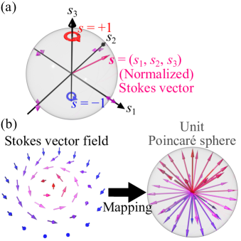
An arbitrary polarization state or a spin state of a photon can be described using a normalized Stokes vector composed of three parameters: . Each parameter corresponds to an expectation value of a Pauli matrix for a photonic spin state Martinelli and Martelli (2017). denotes the orientation of a photonic spin, which can be visualized by a vector arrow drawn in a unit Poincaré sphere, as shown in Fig. 1(a). Figure 1(b) schematically depicts a cross-sectional Stokes vector field of an example FP beam and its projection to the surface of a unit Poincaré sphere. An FP beam possesses any possible spin states in the cross-section, and hence, projecting them to the surface completely wraps the sphere. The topological property or the order of an FP beam is characterized by a skyrmion number that counts the number of times the photonic spins in a certain area () wrap a unit Poincaré sphere, which is expressed as
| (1) |
For an FP beam generated by superposing two beams with opposite SAMs () and different absolute OAMs (), Eq. (1) yields the OAM difference, i.e., . This expression is obtained by integrating Eq. (1) for a domain where the spin state of the superposed beam flips from to (derivation can be found in Supplemental Material (SM)). Therefore, FP beams with any skyrmion numbers can be generated by controlling the OAMs of the beams under superposition Ling et al. (2016); Wang et al. (2017). The capability of generating skyrmions with s much larger than 1 could be of interest, because the extensively investigated magnetic skyrmions frequently exhibit values of only 1 or 2 Ozawa et al. (2017); Zhang et al. (2016).
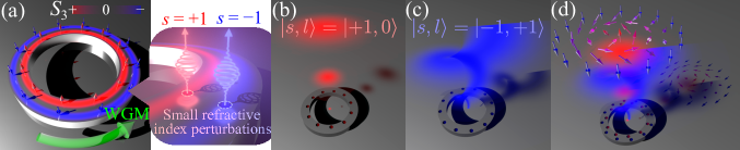
Now, we discuss our scheme of the microcavity-based generation of FP beams. We consider a microring cavity supporting a WGM rotating within the cavity. The tight spatial confinement for the propagating mode induces the spin–orbit interaction of light Luxmoore et al. (2013); Söllner et al. (2015); Coles et al. (2016), and thus leads to the coupling between th e spin and orbit degrees of freedom within the mode. Consequently, the WGM can be described by a superposition of spin-up and spin-down components with angular momentum states of , where is the azimuthal order of the WGM and yields the total angular momentum on multiplication with . Figure 2(a) schematically presents the distribution of the net spin density () of a counterclockwise transverse electric (TE)-like WGM in a microring cavity. The spatial profiles of the spin-up and spin-down modes differ, resulting in the emergence of purely spin polarized lines, known as -lines Yu et al. (2015); Bauer et al. (2016); Garcia-Etxarri (2017). We utilize this phenomenon for achieving SAM-controlled light scattering from the WGM. We apply a small refractive index perturbation aligned to a -line, which selectively scatters circularly polarized photons, with the handedness depending on the polarity of the -line, as schematically shown in the right inset in Fig. 2(a).
By arranging a circular, periodic array of index perturbations, we can control the OAM of the scattered light according to the angular momentum conservation law expressed as Cai et al. (2012); Xiao et al. (2016). Here, is the effective OAM of the WGM that the angular grating feels, is the OAM of the diffracted light, is the diffraction order, and is the number of grating elements. Hereafter, we focus on the first-order diffraction of . Figures 2(b) and (c) show example behaviors of the microcavity with gratings. When an angular grating with is patterned on the -line of , a light beam described by will be generated (Fig. 2(b)). Meanwhile, positioning a grating of on the -line of generates a beam with (Fig. 2(c)).
By arranging the above two gratings in parallel, an FP beam can be synthesized in far field as a superposition of the light beams diffracted by the two grati ngs. The far-field amplitude profile, , of an FP beam generated by our scheme can be analytically approximated by
| (2) |
where is the th-order Bessel function of the first kind, is the wavenumber, is the radius of the circle where the angular grating is patterned, is the azimuth angle, and is the elevation angle ( corresponds to the direction normal to the device plane). This analytical expression was derived with a toy model that assumes each grating element acts as a small electric dipole (see SM and Refs. Ostrovsky et al. (2013); Vaity and Rusch (2015)).
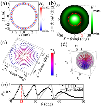
As a specific design of an FP beam generator, we consider a silicon microring cavity with a radius of 3 . The waveguide of the cavity has a width of 450 and a height of 200 , confining a single TE mode at the telecommunication C-band. The refractive indices of silicon and the background environment were set to 3.4 and 1.0, respectively. The ring cavity supports a WGM of an azimuthal order of 24 around a wavelength of 1.57 with a large free spectral range of . This mode has a high factor of without any index perturbation. We focus on the counterclockwise WGM and analyze it using finite-difference time-domain (FDTD) simulations. A calculation domain of and a grid size of were employed in the simulation. We selectively excited the mode in the simulator and continued the computation until the stationary state was reached. Figure 3(a) shows a computed mode profile of the unperturbed micoring cavity. We found -lines of and at the positions respectively deviated by and from the waveguide center in the radial direction. Along each -line, we arranged an array of air holes with a radius and a depth of both 40 . The far fields radiated from the structure were calculated from the obtained near fields using the near-to-far field conversion technique.
First, we designed an FP beam generator emitting a beam with . We patterned 23 holes on the -line of and 24 holes on the -line of , so that the beams in the states of and will be respectively diffracted and superposed. Figure 3(b) presents the intensity profile of the calculated far field within an elevation angle of projected onto a flat plane after collimating the beam virtually. The red dashed line in Fig. 3(b) indicates of 13. The values of 13 and 30 approximately correspond to the first and second minimums in the intensity profile of the light diffracted only by the angular grating of (see SM). Thus, the directions of the spins are expected to be aligned downward () at these angles. Figure 3(c) shows the spatial distribution of the optical spin field within . Spins are directed upward near the center, rotate as changing azimuth angle, and gradually flip their direction to downward as the domain edge is approached. Figure 3(d) plots a projection of the spin texture to a unit Poincaré sphere. The full coverage of the surface demonstrates that the generated beam is indeed an FP beam. The projection map suggests that the observed optical spin field forms a Bloch-type skyrmion. We note that other types of skyrmions, such as Néel-type one, can be generated by rotating one of the angular gratings with respect to the other (not shown).
Subsequently, we calculated according to Eq. (1). The integration was performed from the center to a particular and for all . Figure 3(e) displays the dependence of . At , reaches a near unity value of 0.98, which compares well with the designed value of . The remaining error of 0.02 may be caused by the imperfect circular polarization of the scattered light, resulting from the finite size of the scatter and/or from the multiple reflection of the scattered light before exiting the structure. We also analytically deduced values of using our toy model and overlaid the result on the plot in Fig. 3(e). The analytical curve explains well the FDTD results, in particular when is small, in which case the toy model can be regarded as a good approximation. For both the FDTD and analytical results, we observed oscillations in for . The maxima and minima of the oscillations correspond to the point where the intensity of one of the two scattered beams under superposition approaches zero. Analytically, should oscillate between 0 and the designed , leading to the generation of a skyrmion and an antiskyrmion alternately. This skyrmionic structure is known as a skyrmion multiplex Fujita and Sato (2017), the simplest case of which is known as skyrmionium. Another skyrmion state with , called as half skyrmion or meron Yu et al. (2018), could also be produced by spatially filtering the beam by a diaphragm passing only .
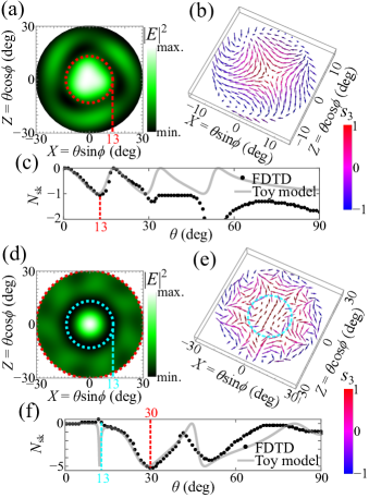
Next, we synthesized an FP beam with or an antiskyrmionic beam. For this, of the grating on the -line of was changed from 24 to 26, so that a beam in a state of will be radiated from the grating. Figures 4(a) and (b) respectively show the computed far-field intensity profile and the corresponding optical spin field within . The latter texture shows an antivortex behavior, as expected. The calculated reaches at , as presented in Fig. 4(c). These results demonstrate that an antiskyrmionic FP beam can also be generated within our scheme. Finally, we present an example device generating an FP beam with a large of . For this demonstration, of the grating on the -line of was increased to 30, which radiatesa beam in the state of . Figures 4(d) and (e) show the computed far-field intensity profile and the corresponding spin field, respectively. From the latter plot, it can be observed that the optical spins wind five times around the field center. Figure 4(f) displays the dependence of the calculated . The minimum of was found at , demonstrating an FP beam with a large of . Meanwhile, for the toy model, should reach close to (indicated by cyan broken lines in Figs. 4(d)–(f)). However, we did not observe an of approximately at in the FDTD simulations. This unexpected behavior in the computation model seemingly arises from the weak diffracted beam in the state of close to . The weak signal is obsecured by the background noise in the simulator, and thus, yields an unpredictable result. Here, the large of the beam induces the weak signal at small values. More robust generation of FP beams with high s could be possible by engineering the size and/or shape of the microring and the pattern of the far fields.
In summary, we demonstrated FP beam generation from a microring cavity. We augmented the microring by angular gratings patterned on the -lines, which diffracted SAM-controlled beams with different OAMs. We showed that the superposition of the beams from the microcavity results in an FP beam with an arbitrary controllable . We examined concrete designs of silicon-based microring cavities and verified the generation of FP beams with various s. We note that the clarified Bessel-like beam patterns of the generated FP beams may lead to their self-healing propagation Vyas et al. (2011); Li et al. (2017); Otte et al. (2018). We believe that the compact FP beam generators could find broad applications in optical communication and optical sensing and play a significant role in exploring condensed matter physics.
Acknowledgements.
This research was supported by JST CREST Grant Number JPMJCR19T1, JSPS KAKENHI Grant Number JP15H05700, JP17H02796, and JP19J13955.References
- Allen et al. (1992) L. Allen, M. W. Beijersbergen, R. J. C. Spreeuw, and J. P. Woerdman, Orbital angular momentum of light and the transformation of laguerre-gaussian laser modes, Physical Review A 45, 8185 (1992).
- Simpson et al. (1997) N. B. Simpson, K. Dholakia, L. Allen, and M. J. Padgett, Mechanical equivalence of spin and orbital angular momentum of light: an optical spanner, Optics Letters 22, 52 (1997).
- Milione et al. (2011) G. Milione, H. I. Sztul, D. A. Nolan, and R. R. Alfano, Higher-order poincaré sphere, stokes parameters, and the angular momentum of light, Physical Review Letters 107, 053601 (2011).
- Yi et al. (2015) X. Yi, Y. Liu, X. Ling, X. Zhou, Y. Ke, H. Luo, S. Wen, and D. Fan, Hybrid-order poincaré sphere, Physical Review A 91, 023801 (2015).
- Naidoo et al. (2016) D. Naidoo, F. S. Roux, A. Dudley, I. Litvin, B. Piccirillo, L. Marrucci, and A. Forbes, Controlled generation of higher-order poincaré sphere beams from a laser, Nature Photonics 10, 327 (2016).
- Liu et al. (2017) Z. Liu, Y. Liu, Y. Ke, Y. Liu, W. Shu, H. Luo, and S. Wen, Generation of arbitrary vector vortex beams on hybrid-order poincaré sphere, Photonics Research 5, 15 (2017).
- Beckley et al. (2010) A. M. Beckley, T. G. Brown, and M. A. Alonso, Full poincaré beams, Optics Express 18, 10777 (2010).
- Suárez-Bermejo et al. (2019) J. C. Suárez-Bermejo, J. C. G. de Sande, M. Santarsiero, and G. Piquero, Mueller matrix polarimetry using full poincaré beams, Optics and Lasers in Engineering 122, 134 (2019).
- Wang (2012) L.-G. Wang, Optical forces on submicron particles induced by full poincaré beams, Optics Express 20, 20814 (2012).
- Zhu et al. (2015) W. Zhu, V. Shvedov, W. She, and W. Krolikowski, Transverse spin angular momentum of tightly focused full poincaré beams, Optics Express 23, 34029 (2015).
- Ling et al. (2016) X. Ling, X. Yi, Z. Dai, Y. Wang, and L. Chen, Characterization and manipulation of full poincaré beams on the hybrid poincaré sphere, Journal of the Optical Society of America B 33, 2172 (2016).
- Wang et al. (2017) J. Wang, L. Wang, and Y. Xin, Generation of full poincaré beams on arbitrary order poincaré sphere, Current Optics and Photonics 1, 631 (2017).
- Galvez et al. (2012) E. J. Galvez, S. Khadka, W. H. Schubert, and S. Nomoto, Poincaré-beam patterns produced by nonseparable superpositions of laguerre–gauss and polarization modes of light, Applied Optics 51, 2925 (2012).
- Shvedov et al. (2015) V. Shvedov, P. Karpinski, Y. Sheng, X. Chen, W. Zhu, W. Krolikowski, and C. Hnatovsky, Visualizing polarization singularities in bessel-poincaré beams, Optics Express 23, 12444 (2015).
- Lopez-Mago (2019) D. Lopez-Mago, On the overall polarisation properties of poincaré beams, Journal of Optics 21, 115605 (2019).
- Donati et al. (2016) S. Donati, L. Dominici, G. Dagvadorj, D. Ballarini, M. De Giorgi, A. Bramati, G. Gigli, Y. G. Rubo, M. H. Szymańska, and D. Sanvitto, Twist of generalized skyrmions and spin vortices in a polariton superfluid, Proceedings of the National Academy of Sciences 113, 14926 (2016).
- Gao et al. (2019) S. Gao, J. B. Götte, F. C. Speirits, N. Radwell, S. Franke-Arnold, and S. M. Barnett, Skyrmionic beams (2019), arXiv:1906.05333 [physics.optics] .
- Yu et al. (2010) X. Z. Yu, Y. Onose, N. Kanazawa, J. H. Park, J. H. Han, Y. Matsui, N. Nagaosa, and Y. Tokura, Real-space observation of a two-dimensional skyrmion crystal, Nature 465, 901 (2010).
- Choi et al. (2012) J.-y. Choi, W. J. Kwon, and Y.-i. Shin, Observation of topologically stable 2d skyrmions in an antiferromagnetic spinor bose-einstein condensate, Physical Review Letters 108, 035301 (2012).
- Fukuda and Zumer (2011) J.-i. Fukuda and S. Zumer, Quasi-two-dimensional skyrmion lattices in a chiral nematic liquid crystal, Nature Communications 2, 246 (2011).
- Cilibrizzi et al. (2016) P. Cilibrizzi, H. Sigurdsson, T. C. H. Liew, H. Ohadi, A. Askitopoulos, S. Brodbeck, C. Schneider, I. A. Shelykh, S. Höfling, J. Ruostekoski, and P. Lagoudakis, Half-skyrmion spin textures in polariton microcavities, Physical Review B 94, 045315 (2016).
- Tsesses et al. (2018) S. Tsesses, E. Ostrovsky, K. Cohen, B. Gjonaj, N. H. Lindner, and G. Bartal, Optical skyrmion lattice in evanescent electromagnetic fields, Science 361, 993 (2018).
- Du et al. (2019) L. Du, A. Yang, A. V. Zayats, and X. Yuan, Deep-subwavelength features of photonic skyrmions in a confined electromagnetic field with orbital angular momentum, Nature Physics 15, 650 (2019).
- Bai et al. (2020) C. Bai, J. Chen, Y. Zhang, D. Zhang, and Q. Zhan, Dynamic tailoring of an optical skyrmion lattice in surface plasmon polaritons, Optics Express 28, 10320 (2020).
- Guo et al. (2020) C. Guo, M. Xiao, Y. Guo, L. Yuan, and S. Fan, Meron spin textures in momentum space, Physical Review Letters 124, 106103 (2020).
- Wang et al. (2019) K. Wang, X. Qiu, L. Xiao, X. Zhan, Z. Bian, B. C. Sanders, W. Yi, and P. Xue, Observation of emergent momentum-time skyrmions in parity-time-symmetric non-unitary quench dynamics, Nature Communications 10, 2293 (2019).
- Wätzel and Berakdar (2020) J. Wätzel and J. Berakdar, Topological light fields for highly non-linear charge quantum dynamics and high harmonic generation, Optics Express 28, 19469 (2020).
- Bauer et al. (2015) T. Bauer, P. Banzer, E. Karimi, S. Orlov, A. Rubano, L. Marrucci, E. Santamato, R. W. Boyd, and G. Leuchs, Observation of optical polarization möbius strips, Science 347, 964 (2015).
- Luxmoore et al. (2013) I. J. Luxmoore, N. A. Wasley, A. J. Ramsay, A. C. T. Thijssen, R. Oulton, M. Hugues, S. Kasture, V. G. Achanta, A. M. Fox, and M. S. Skolnick, Interfacing spins in an ingaas quantum dot to a semiconductor waveguide circuit using emitted photons, Physical Review Letters 110, 037402 (2013).
- Söllner et al. (2015) I. Söllner, S. Mahmoodian, S. L. Hansen, L. Midolo, A. Javadi, G. Kirsanske, T. Pregnolato, H. El-Ella, E. H. Lee, J. D. Song, S. Stobbe, and P. Lodahl, Deterministic photon-emitter coupling in chiral photonic circuits, Nature Nanotechnology 10, 775 (2015).
- Coles et al. (2016) R. J. Coles, D. M. Price, J. E. Dixon, B. Royall, E. Clarke, P. Kok, M. S. Skolnick, A. M. Fox, and M. N. Makhonin, Chirality of nanophotonic waveguide with embedded quantum emitter for unidirectional spin transfer, Nature Communications 7, 11183 (2016).
- Cai et al. (2012) X. Cai, J. Wang, M. J. Strain, B. Johnson-Morris, J. Zhu, M. Sorel, J. L. O’Brien, M. G. Thompson, and S. Yu, Integrated compact optical vortex beam emitters, Science 338, 363 (2012).
- Xiao et al. (2016) Q. Xiao, C. Klitis, S. Li, Y. Chen, X. Cai, M. Sorel, and S. Yu, Generation of photonic orbital angular momentum superposition states using vortex beam emitters with superimposed gratings, Optics Express 24, 3168 (2016).
- Shao et al. (2018) Z. Shao, J. Zhu, Y. Chen, Y. Zhang, and S. Yu, Spin-orbit interaction of light induced by transverse spin angular momentum engineering, Nature Communications 9, 926 (2018).
- Martinelli and Martelli (2017) M. Martinelli and P. Martelli, Polarization, mirrors, and reciprocity: birefringence and its compensation in optical retracing circuits, Advances in Optics and Photonics 9, 129 (2017).
- Ozawa et al. (2017) R. Ozawa, S. Hayami, and Y. Motome, Zero-field skyrmions with a high topological number in itinerant magnets, Physical Review Letters 118, 147205 (2017).
- Zhang et al. (2016) X. Zhang, Y. Zhou, and M. Ezawa, High-topological-number magnetic skyrmions and topologically protected dissipative structure, Physical Review B 93, 024415 (2016).
- Yu et al. (2015) R. Yu, Y. Xin, Q. Zhao, Y. Shao, and Y. Chen, Exceptional polarization structures near the c-lines in diffracted near fields, Journal of the Optical Society of America A 32, 1468 (2015).
- Bauer et al. (2016) T. Bauer, M. Neugebauer, G. Leuchs, and P. Banzer, Optical polarization möbius strips and points of purely transverse spin density, Physical Review Letters 117, 013601 (2016).
- Garcia-Etxarri (2017) A. Garcia-Etxarri, Optical polarization möbius strips on all-dielectric optical scatterers, ACS Photonics 4, 1159 (2017).
- Ostrovsky et al. (2013) A. S. Ostrovsky, C. Rickenstorff-Parrao, and V. Arrizón, Generation of the “perfect” optical vortex using a liquid-crystal spatial light modulator, Optics Letters 38, 534 (2013).
- Vaity and Rusch (2015) P. Vaity and L. Rusch, Perfect vortex beam: Fourier transformation of a bessel beam, Optics Letters 40, 597 (2015).
- Fujita and Sato (2017) H. Fujita and M. Sato, Ultrafast generation of skyrmionic defects with vortex beams: Printing laser profiles on magnets, Physical Review B 95, 054421 (2017).
- Yu et al. (2018) X. Z. Yu, W. Koshibae, Y. Tokunaga, K. Shibata, Y. Taguchi, N. Nagaosa, and Y. Tokura, Transformation between meron and skyrmion topological spin textures in a chiral magnet, Nature 564, 95 (2018).
- Vyas et al. (2011) S. Vyas, Y. Kozawa, and S. Sato, Self-healing of tightly focused scalar and vector bessel–gauss beams at the focal plane, Journal of the Optical Society of America A 28, 837 (2011).
- Li et al. (2017) P. Li, Y. Zhang, S. Liu, H. Cheng, L. Han, D. Wu, and J. Zhao, Generation and self-healing of vector bessel-gauss beams with variant state of polarizations upon propagation, Optics Express 25, 5821 (2017).
- Otte et al. (2018) E. Otte, I. Nape, C. Rosales-Guzmán, A. Vallés, C. Denz, and A. Forbes, Recovery of nonseparability in self-healing vector bessel beams, Physical Review A 98, 053818 (2018).