On Session Continuation among Slices for Inter-Slice Mobility Support in 3GPP Service-based Architecture
Abstract
The 3GPP has provided its first standard specifications for network slicing in the recent Release 15. The fundamental principles are specified which constitute the standard network slicing framework. These specifications, however, lack the session continuation mechanisms among slices, which is a fundamental requirement to achieve inter-slice mobility. In this paper, we propose three solutions which enable session continuation among slices in the current 3GPP network slicing framework. These solutions are based on existing, well-established standard mechanisms. The first solution is based on the Return Routability/Binding Update (RR/BU) procedure of the popular Internet standard, Mobile IPv6 (MIPv6). The second solution is based on the 3GPP standard GPRS Tunnelling Protocol User Plane (GTPv1-U), which establishes a GTP tunnel between previous and new slice for session continuation. The third solution is a hybrid solution of both MIPv6-RR/BU and GTPv1-U protocols. We compare the performance of all these solutions through analytical modelling. Results show that the GTPv1-U based and the hybrid MIPv6/GTPv1-U solutions promise lower service disruption latency, however, incur higher resource utilization overhead compared to MIPv6-RR/BU and 3GPP standard PDU Session Establishment process.
Index Terms:
Network Slicing, Inter-slice Mobility Management, Service-based Architecture, GTPv1-U, 5G/3GPP StandardizationI Introduction
Network Slicing has emerged as a key enabling technology for 5G, which provides different services types over a common network infrastructure. The 3GPP has provided a baseline framework for network slicing in its recent Release 15, which is based on a novel Service-based Architecture (SBA). The ongoing 3GPP standardization on 5G provides more clarity on real-world semantics, requirements and challenges of a sliced mobile network. Among these, the challenge of managing mobility among different SBA slices, or Inter-Slice Handovers (ISHOs) is an important problem.
As stated in [1, 2], inter-slice mobility management requires new solutions. Most of the existing literature on mobility management in a sliced network focuses on managing slice-aware horizontal [5, 4] or vertical handovers [3]. The problem of inter-slice mobility management is considered only by a limited studies. An ISHO solution in [9] proposes virtualized mobility management applications, which can manage ISHOs in a softwarized network. Some other ISHO solutions consider specific vehicular communications use case of network slicing [8, 6]. However, none of the existing works have considered the network slicing framework of the 3GPP SBA. As such, the problem of managing mobility between slices in 3GPP SBA remains an open issue.
Inter-slice mobility management requires smooth session continuation or session transfer among slices when a user moves from one slice to another. Different session types including IP, Ethernet, and Unstructured are defined by 3GPP to support different service types. However, the session continuation support is available only between 3GPP and non-3GPP access networks and the LTE’s Evolved Packet System (EPS) to 5G core (5GC). The current 3GPP specifications do not support session continuation among slices.
Thus, in this paper, we focus on the problem of session continuation among slices. The sessions of type IP, and among these IPv6, are considered which are expected to support a wide spectrum of 5G use cases. We present three solutions which are based on existing, well-established standard mechanisms. The first solution is based on Return Routability/Binding Update (RR/BU) procedure of the popular IETF (Internet Engineering Task Force) Mobile IPv6 (MIPv6) protocol [12]. This solution, termed as MIPv6-RR/BU, is based on a proposed concept of Home Slice, through which the User Equipment (UE) communicates with the external Data Network (DN) using MIPv6 signalling. Through MIPv6 signalling, the UE requests the DN to redirect the ongoing traffic to its new slice. The second solution is based on the 3GPP’s standard user plane tunnelling protocol, called GPRS Tunnelling Protocol User Plane (GTPv1-U) [13]. In this solution, a new functional entity at data plane, named Inter-Slice Gateway (ISGW), is proposed which manages an inter-slice GTP tunnel. The third solution is a hybrid solution of MIPv6-RR/BU and GTPv1-U protocols, and is termed as MIPv6/GTPv1-U. In this solution, traffic tunnelling through GTP occurs temporarily until the MIPv6-RR/BU operations complete. Through analytical modelling, we have compared the inter-slice handover performance and have highlighted the pros and cons of each solution.
The remainder of this paper is organized as follows. In Section II, we briefly review the network slicing framework for SBA as specified by the 3GPP. In particular, the standard principles related to a UE’s movement from one slice to another, are discussed. Thereafter, in Section III, we present the proposed solutions. Section IV, presents analytical models, and the comparative analysis based on these models is given in Section V. Finally, we conclude this paper in Section VI.
II 3GPP Network Slicing Framework
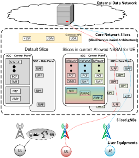
The 3GPP defines a network slice as a logical network with specific network capabilities. A logical network or a slice consists of a set of (usually virtual) network functions (NFs). In SBA, an individual slice is identified through an S-NSSAI (Single-Network Slice Selection Identifier). A mobile network domain can have multiple slices configured, which are (collectively) termed as Configured NSSAI. A UE can subscribe to multiple slices in the network which are termed as Subscribed S-NSSAIs. However, at any given time, the network allows a UE to connect to only a limited number of slices, which are identified as Allowed NSSAI. The network can usually serve the UE through a default slice, when the UE does not show its preference to any particular slice(s). A typical network-sliced SBA is shown in Fig. 1. Full definition of the NFs in SBA can be found in [10].
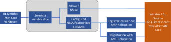
When a UE wishes to (or is forced by the network to) change its slice, it has choice to select its alternate slice from the Allowed NSSAI. If the desired slice is not present in Allowed NSSAI, and it wishes to connect to a slice in the Configured NSSAI/Subscribed S-NSSAI, it is first required to carry out Registration to obtain its desired slices in Allowed NSSAI. The Registration process may in turn result in relocation of the current Access and Mobility Management Function (AMF) serving the UE (e.g., from AMF-1 to AMF-2 in Fig. 1). Hence, the inter-slice mobility can occur in several forms, which we have discussed in our recent work in [7]. In this paper, we consider a specific case when a UE has its desired alternate slice in Allowed NSSAI, either already present, or obtained after performing Registration. This process is shown in Fig. 2.
According to the current specification, when a UE wishes to move from one slice to another, it is required to (re-)establish its session over new slice for service continuation. The PDU Session (re-)establishment request for this purpose triggers the AMF to release the UE’s session through Session Management Function (SMF) at previous slice [11]. Intuitively, this process is prone to significant service disruptions and packet drops. Hence, the inter-slice mobility of a UE requires smooth continuation of its ongoing session among slices.
III Proposed Solutions
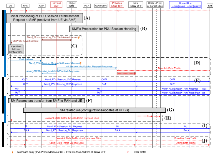
In this section, we present three approaches for inter-slice session continuity of IPv6 sessions. These solutions have several common operations and are hence collectively represented in Fig. 3. All these solutions consider the standard PDU Session establishment process [11] as a baseline, and enhance it either with MIPv6-RR/BU, inter-slice GTP tunnelling, or combination of both.
III-A MIPv6-RR/BU-based Session Continuation
Mobile IPv6 is developed to enable session continuity of a user when it moves out of its home network, and roams around different IP domains. The user remains reachable to its home network by updating it with its new (temporary) IPv6 address. The user thus continues to receive traffic at its new location via home network. However, this causes significant overheads [16], and hence the direct traffic exchange between user and the correspondent node (CN) from new network is enabled, as the user completes the Return Routability (RR) and Binding Update (BU) with the CN [12].
The proposed MIPv6-RR/BU-based session continuation solution is based on the RR/BU procedures of MIPv6. Corresponding to home network in MIPv6, we propose a concept of “Home Slice”, wherein the default slice of UE functions as its home slice. The home slice remains reachable to UE via its current RAN or AMF. The UE’s subscription data remains available at its Home AMF (H-AMF) and Home SMF (H-SMF), even when the home slice is removed from the Allowed NSSAI. This allows any control plane signalling exchange between UE and DN over the home slice. The full protocol operation in MIPv6-RR/BU-based session continuation consists of Steps (A)-(C), (E)-(G), and (I)-(J) shown in Fig. 3, and are briefly described below.
(A) The UE, on deciding ISHO (and acquiring the desired slice in Allowed NSSAI), sends the standard “PDU Session Establishment Request” message to its current AMF. A new Request Type “Existing PDU Session Takeover Request” is proposed which indicates that the request message is about an ongoing session to be taken over from another slice. The AMF selects a suitable SMF for UE, and transfers the received request to SMF. The SMF, on checking its Request Type, learns of an existing session from another slice. It then verifies the subscription information of UE, which it can retrieve from the Unified Data Management/Repository (UDM/UDR). After verification, it creates a Session Management (SM) context and responds to the AMF [11].
(B) The SMF starts preparation to handle (or takeover) the existing session. For this purpose, it performs three key standard operations: (a) It selects and establishes the policy association with a Policy Control Function (PCF) which provides policy rules. (b) It selects the User Plane Functions (UPFs) which will handle the data plane traffic. The SMF also performs the N4 sessions establishment which enables SMF-UPF interaction with the selected UPF(s), and deploys policy rules on these UPF(s). (c) The SMF allocates the IP address for UE (i.e., an IPv6 prefix for an IPv6 PDU Session) [11].
(C) In 3GPP specifications, the allocated IP information (i.e., an IPv6 Prefix) is shared with UE after the standard “PDU Session Establishment” process completes [11]. For ISHO support, we propose that the SMF shares the IP information with UE as it is allocated. For this purpose, the SMF invokes the proposed IPv6PrefixAdvertisement service operation of the standard Namf_Communication service with AMF. The AMF carries out the IPv6 Prefix Advertisement, and the UE can configure its new IPv6 address using the received prefix through stateless IPv6 address autoconfiguration [14].
(E) The UE having new IPv6 address is ready to carry out RR. It creates the standard MIPv6 messages – Home Test Init (HoTI), and Care-of Test Init (CoTI). The UE sends the CoTI message to the DN via new slice, while the HoTI message is sent via Home Slice. The DN responds to both messages with CoT and HoT messages. New service operations, CoT and HoT are proposed to the standard Nsmf_PDUSession service, to enable transmission of CoTI/CoT and HoTI/HoT messages respectively between AMF and SMF (as shown in Fig. 3).
(F) The SMF, on the other hand, is also required to carry out the QoS and other resources set up at RAN and UE for proper handling of the PDU Session. On successful configurations, the PDU Session Establishment Accept message is also delivered to the UE [11].
(G) The SMF carries out the N4 sessions modification with UPFs if QoS configurations and resources set up at RAN and UE require parameters re-adjustments at the core network [11].
(I) After Step (F), provided that RR completes successfully, the UE can send the MIPv6 standard Binding Update (BU) message to the DN over the new slice. The DN, on receiving and verifying the BU, responds the UE with Binding Acknowledgement (BAck) message.
(J) The acceptance of BU in Step (I) also triggers the DN to direct the ongoing traffic of the UE over its new slice.
III-B GTPv1-U based Session Continuation
The GTPv1-U is a default user plane tunnelling protocol in 3GPP specifications for 5G [10]. It handles tunnelling between two UPFs, and also between a UPF and a 5G access network node (e.g., a gNB). In GTPv1-U, a datagram (e.g., an IP datagram) is encapsulated in a GTPv1-U header and then in a UDP/IP header [13].
In order to support GTP tunnelling among slices, the proposed ISGW operates on a UPF (hence termed as ISGW-UPF). The ISGW-UPF establishes the GTPv1-U tunnel with its peer ISGW-UPF in the Target Slice. This solution consists of Steps (A)-(D) and (F)-(H) as shown in Fig. 3. In addition to the details described in Section III-A, following additional operations take place in each step.
(A) When the AMF receives the PDU Session Establishment Request, it is required to coordinate with both slices (i.e., previous slice and the new slice). It coordinates with the new slice first in Step (A), and if the new slice is willing to cater the UE’s session, then the AMF (later on in Step (D)) coordinates with previous slice to request it to divert the UE’s traffic towards new slice.
(B) The N4 sessions establishment in Step (B) includes configurations for ISGW-UPF as well. This prepares the ISGW-UPF to cater the UE’s traffic in both uplink/downlink directions to/from another slice.
(C) The SMF also includes the IPv6 address of the ISGW-UPF interface which will receive the incoming traffic from the previous slice, when it invokes the proposed Namf_Communication_IPv6PrefixAdvertisement service operation with AMF (Fig. 3).
(D) The UE, after configuring its new IPv6 address in Step (C), communicates it to AMF. The AMF provides the IPv6 Address to previous slice through Nsmf_PDUSession_UpdateSMContext Request. The IPv6 interface address of the ISGW-UPF of new slice is also included. The SMF performs N4 sessions modification with ISGW-UPF to enable GTPv1-U tunnel establishment with ISGW-UPF in the target slice. The UE’s incoming traffic is subsequently tunnelled to the ISGW-UPF in the target slice.
(H) The new slice starts receiving traffic from the previous slice, and delivers it to the UE, as shown in Fig. 3.
III-C MIPv6/GTPv1-U based Session Continuation
The MIPv6/GTPv1-U solution is the combination of MIPv6-RR/BU and the GTPv1-U based session continuation solutions. In MIPv6/GTPv1-U, the incoming traffic of UE at previous slice is tunnelled to new slice temporarily. As the AMF detects BAck (in Step (H)), it can invoke the standard Nsmf_PDUSession_ReleaseSMContext service operation with SMF at previous slice [11] to release the tunnel. The full operation of MIPv6/GTPv1-U consists of Steps (A)-(J), as described in Section III-A and the Section III-B, and shown in Fig. 3.
IV Analytical Modelling
In this section, through analytical modelling, we compare the performance of proposed solutions with the baseline PDU Session Establishment process [11]. Several notations used in analytical modelling are defined in Table II.
System Modelling
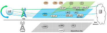
For comparative analysis, we consider the system model shown in Fig. 4. The core network NFs are assumed to be virtual NFs deployed at commodity hardware, which can be dedicated or shared among virtual NFs. The data plane consists of UPFs, which include a GW-UPF, the proposed ISGW-UPF, an N3-UPF which terminates the N3 reference point with RAN [10] and other UPFs as required. A common data plane will normally configure 2 or 3 UPFs [15]. At RAN, a sliced gNB is considered which supports both current and target slice of UE. Since the signalling related to the PDU Session management is handled from the 5GC, the primary focus of our work remains on the inter-action between UE, the 5GC and the DN.
Mobility Modelling
The inter-slice mobility does not necessarily require physical mobility of the UE. We assume that the current gNB supports both slices, and the UE does not change the gNB during the inter-slice handover. It is worth remarking that should the inter-slice handover occurs as a result of UE’s movement towards another gNB or different access technology, then the horizontal and vertical handover management procedures will also be required, respectively. These will precede the inter-slice handover operation. Both these cases represent complex mobility management scenarios, and require further investigations [7].
IV-1 ISHO Delay and ISHO Interval
The ISHO delay is defined as the time interval from the instance when the UE receives the last downlink packet at previous slice, to the instance when it receives the first downlink packet (or can send the first uplink packet) from new slice. We also define the total ISHO interval, which is the duration from when the UE starts the ISHO process until it completes. The ISHO delay and the total ISHO Interval are represented respectively as , and . The notation , hereinafter, is used to represent either of the proposed schemes (i.e., MIPv6-RR/BU as , GTPv1-U as , MIPv6/GTPv1-U as ) as well as the baseline PDU Session Establishment procedure (as ). The expressions for and are given in Table I, where the terms to represent the delays associated to Steps (A) to (J) in Fig. 3. These delays are sum of the transmission delays () between a node (or an NF) and another node (or NF) , and processing delays () at any node (or NF) [16]. These are simple to formulate, for instance, can be given as,
| (1) |
Similar expressions can also be formulated for and which represent the standard “Secondary Authentication/Authorization” for UE by DN and “IPv6 Advertisement” by SMF to UE via UPF(s) [11] respectively.
IV-2 Core Network Resources Overhead
The core network resource overhead represents the overall resource consumption by a flow at the data plane of a slice. These resources include the fraction of CPU resources (), and the fraction of link bandwidth resources (), allocated to an ongoing flow [17]. Their respective overheads are represented as and . Assuming that these resources are statically allocated, and can be given as,
| (2) |
| (3) |
| Notation | Description | Default Values |
|---|---|---|
| Avg. Transmission delay between two control plane SBA NFs | 1 ms | |
| Avg. Transmission delay between a non-SBA node and another node (or an SBA NF) | Manifold, defined in Section V-1 | |
| Avg. Processing delay at SBA CP NF | 1 ms | |
| Avg. Processing delay at non-SBA node | Manifold, defined in Section V-1 | |
| Maximum No. of UPFs deployed at previous/new slice | 3 | |
| No. of UPFs currently handling UE traffic at previous/new slice | 1, | |
| No. of UPFs at new Slice handling incoming traffic from previous | ||
| Total No. of UPFs between GW-UPF and ISGW-UPF at Previous, new Slice | 1, 0 | |
| , | Fraction of CPU processing resources allocated to a flow at | 100 packets/sec. |
| Avg. Processing Cost of a control packet at an NF in SBA, or non-SBA node | 1, 5 | |
| Avg. Transmission cost between two NFs at SBA | 1 | |
| Avg. Transmission cost between a node (or NF) to another node (or NF) | 2 |
and are the ratios of traffic from indirect path (i.e., via previous slice) and the direct path (i.e., via new slice) respectively.
For and , , , .
For and , , , .
For and , , , .
For and , , , .
IV-3 Signalling Cost
V Results
For comparison, the default values of system parameters are shown in Table II. Most of these are based on [19, 20, 16, 21, 18].
V-1 ISHO Interval and ISHO Delay Analysis
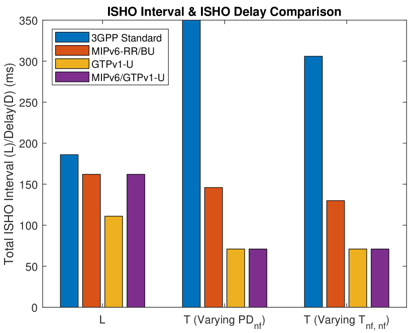
We study the impact of varying characteristics of the SBA slices in terms of the and . The lower and higher values of these parameters characterize the control plane virtual NFs deployments at shared and dedicated hardware with shared and dedicated resources respectively. Other parameter values are set as, , , , , . The for any non-SBA node , and are set to . These non-SBA nodes include UE, DN, and gNB. As shown in Fig. 8, for total ISHO interval, with default and values, only the GTPv1-U solution shows notable reduction of about 40% compared to the standard 3GPP process. However, all the proposed solutions achieve significant reduction for ISHO delay. For values varied from 1 to 5 (), the MIPv6-RR/BU can achieve approximately 60% reduction in ISHO delay compared to the standard 3GPP process. On the other hand, the GTPv1-U based solutions (i.e., GTPv1-U and MIPv6/GTPv1-U) achieve up to 80% reduction in the overall delay. For values varied from 1 to 5 (), the MIPv6-RR/BU and GTPv1-U (and MIPv6/GTPv1-U) achieve 58% and 76% reduction in ISHO delay respectively, compared to the standard 3GPP process.
V-2 Resource Overhead Analysis
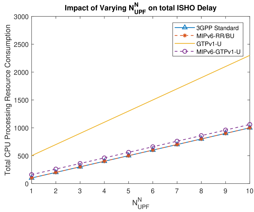
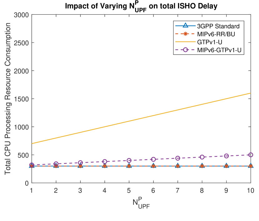
For resource overhead analysis, we consider a worst case scenario, where an ISGW-UPF is deployed at N3-UPF at previous slice, and at GW-UPF at the new slice. Hence, , and . For MIPv6/GTPv1-U, we set [19]. Multiple UPFs, especially for geographically widespread slices (e.g., for rate limiting, executing different QoS policies in different segments of the core network) are also likely. Accordingly, we vary and , to analyze the overall resource overhead. In this analysis, we only consider the , since the for each scheme is of the same proportion. Fig. 8 shows that, with varying , the MIPv6-RR/BU incurs minimal resource overheads compared to GTPv1-U and MIPv6/GTPv1-U solutions. In fact, the resource overhead of MIPv6-RR/BU is similar to the standard 3GPP solution, since neither of these solutions require resources from previous slice due to direct communication establishment between UE and DN. The MIPv6/GTPv1-U solution, which only requires previous slice resources temporarily, shows significant reduction in resource consumptions, compared to the GTPv1-U solution. On the other hand, varying , as shown in Fig. 8, the MIPv6/GTPv1-U for lower incurs approximately similar resource overheads as 3GPP standard process and MIPv6-RR/BU solutions respectively.
V-3 Signalling Cost Analysis
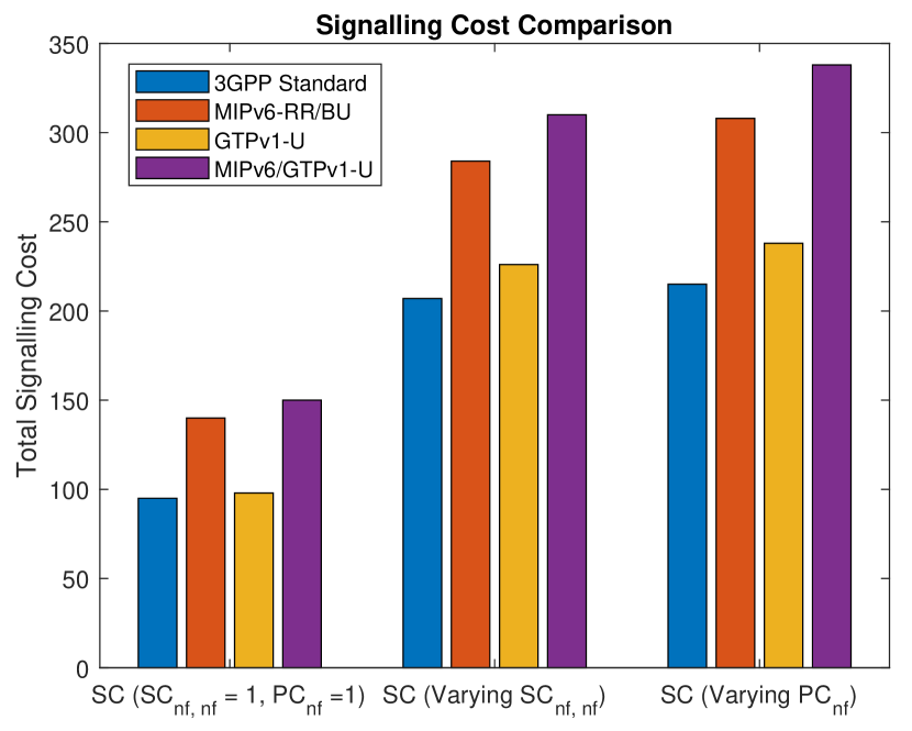
The signalling cost metric aptly represents the control plane traffic overhead incurred by each scheme. For the signalling cost comparison, it is clear from Fig. 8 that all the proposed solutions achieve session continuation at the cost of additional signalling. Among these, the GTPv1-U based session continuation incurs only 3% additional costs compared to the standard 3GPP process, and up to 10% additional costs for higher or values. The MIPv6-RR/BU solution incurs about 35-45% costs, while MIPv6/GTPv1-U incurs between 55-60% additional costs.
VI Conclusion
In this paper, we have proposed and analyzed three solutions to achieve session continuation among slices in 3GPP SBA. Among the proposed solutions, the GTPv1-U based solution incurs minimal latencies, and lower signalling costs. However, it incurs significantly higher resource overheads. The MIPv6-RR/BU, on the other hand, promises comparatively lower resource overhead costs, however, incurs higher latencies and signalling costs. Their combination MIPv6/GTPv1-U achieves lower latencies, and also improves resource overhead costs. However, it incurs significantly high signalling costs. This demonstrates the need for further investigations on the problem of ISHOs, which, given high reliance of conceived 5G use cases on network slicing, is a significant problem.
References
- [1] X. Foukas, et al., “Network Slicing in 5G: Survey and Challenges,” in IEEE Communications Magazine, vol. 55, no. 5, pp. 94-100, May 2017.
- [2] X. Li et al., “Network Slicing for 5G: Challenges and Opportunities,” in IEEE Internet Computing, vol. 21, no. 5, pp. 20-27, 2017.
- [3] A. N. Manjeshwar, et al., “Enhanced UE Slice Mobility for 5G Multi-RAT Networks,” 2019 IEEE Conference on Network Function Virtualization and Software Defined Networks (NFV-SDN), Dallas, TX, USA, 2019, pp. 1-6.
- [4] R. Wen, et al., “Mobility Management for Network Slicing Based 5G Networks,” 2018 IEEE 18th International Conference on Communication Technology (ICCT), Chongqing, 2018, pp. 291-296.
- [5] H. Zhang, et. al, “Network Slicing Based 5G and Future Mobile Networks: Mobility, Resource Management, and Challenges,” in IEEE Communications Magazine, vol. 55, no. 8, pp. 138-145, Aug. 2017.
- [6] A. Kammoun, et al., “Inter-slice Mobility Management in the Context of SDN/NFV Networks,” in Distributed Computing for Emerging Smart Networks, Cham, 2020, pp. 77-90.
- [7] Sajjad, M. M., Bernardos, C. J., Jayalath, D., & Tian, Y. C. (2020). Inter-Slice Mobility Management in 5G: Motivations, Standard Principles, Challenges and Research Directions. arXiv preprint arXiv:2003.11343.
- [8] N. Mouawad, R. Naja and S. Tohme, “Inter-Slice Mobility Management Solution In V2X Environment,” 2019 International Conference on Wireless and Mobile Computing, Networking and Communications (WiMob), Barcelona, Spain, 2019, pp. 1-6.
- [9] F. Z. Yousaf, et al., “Network slicing with flexible mobility and QoS/QoE support for 5G Networks,” in 2017 IEEE International Conference on Communications Workshops (ICC Workshops), May 2017, pp. 1195–1201.
- [10] System Architecture for the 5G System; Stage 2 Release 15, 3GPP Std. TS 23.501, Rev. V15.4.0, Dec. 2018.
- [11] Procedures for the 5G System; Stage 2 Release 15, 3GPP Std. TS 23.502, Rev. V15.4.1, Jan. 2019.
- [12] C. Perkins, D. Johnson, J. Arkko, Mobility Support in IPv6, IETF RFC 6275, July 2011.
- [13] General Packet Radio System (GPRS) Tunnelling Protocol User Plane (GTPv1‐U); Release 15, 3GPP Std. TS 29.281, v15.7.0, December 2019.
- [14] S. Thomson, T. Narten, and T. Jinmei, “IPv6 Stateless Address Autoconfiguration,” IETF RFC 4862, September 2007.
- [15] User Plane Protocol and Architectural Analysis on 3GPP 5G System, draft-ietf-dmm-5g-uplane-analysis-03 (work in progress), November, 2019.
- [16] C. Makaya and S. Pierre, “An Analytical Framework for Performance Evaluation of IPv6-Based mobility Management Protocols,” IEEE Transactions on Wireless Communications, vol. 7, no. 3, pp. 972–983, March 2008.
- [17] Q. Ye, et al., “End-to-End Delay Modeling for Embedded VNF Chains in 5G Core Networks,” in IEEE Internet of Things Journal, vol. 6, no. 1, pp. 692-704, Feb. 2019.
- [18] J. Prados-Garzon, et al., “A Complete LTE Mathematical Framework for the Network Slice Planning of the EPC,” in IEEE Transactions on Mobile Computing, vol. 19, no. 1, pp. 1-14, 1 Jan. 2020.
- [19] J. Lee, T. Ernst and T. Chung, “Cost analysis of IP mobility management protocols for consumer mobile devices,” in IEEE Transactions on Consumer Electronics, vol. 56, no. 2, pp. 1010-1017, May 2010.
- [20] M. Gohar and J. Choi, “Enhanced Mobility Management Scheme in PMIP-SAE-Based Mobile Networks,” in IEEE Communications Letters, vol. 20, no. 6, pp. 1160-1163, June 2016.
- [21] A. Jain, E. Lopez-Aguilera and I. Demirkol, “Improved Handover Signaling for 5G Networks,” 2018 IEEE 29th Annual International Symposium on Personal, Indoor and Mobile Radio Communications (PIMRC), Bologna, 2018, pp. 164-170.