Demonstration of an All-Microwave Controlled-Phase Gate
between Far Detuned Qubits
Abstract
A challenge in building large-scale superconducting quantum processors is to find the right balance between coherence, qubit addressability, qubit-qubit coupling strength, circuit complexity and the number of required control lines. Leading all-microwave approaches for coupling two qubits require comparatively few control lines and benefit from high coherence but suffer from frequency crowding and limited addressability in multi-qubit settings. Here, we overcome these limitations by realizing an all-microwave controlled-phase gate between two transversely coupled transmon qubits which are far detuned compared to the qubit anharmonicity. The gate is activated by applying a single, strong microwave tone to one of the qubits, inducing a coupling between the two-qubit and states, with , , and denoting the lowest energy states of a transmon qubit. Interleaved randomized benchmarking yields a gate fidelity of at a gate duration of , with the dominant error source being decoherence. We model the gate in presence of the strong drive field using Floquet theory and find good agreement with our data. Our gate constitutes a promising alternative to present two-qubit gates and could have hardware scaling advantages in large-scale quantum processors as it neither requires additional drive lines nor tunable couplers.
I Introduction
Superconducting circuits making use of the concepts of circuit quantum electrodynamics Blais et al. (2020) constitute a promising platform for quantum computing. Recently, processors containing several tens of superconducting qubits have been demonstrated Cross et al. (2019); Otterbach et al. (2017); Arute et al. (2019). While high-fidelity single-qubit operations with error rates below 0.1% are routinely achieved, two-qubit gate errors are typically at the percent level Kjaergaard et al. (2020a); Gambetta et al. (2017), with only a few recent experiments achieving two-qubit gate errors of a few per mill Barends et al. (2019); Foxen et al. (2020); Kjaergaard et al. (2020b). Hence, two-qubit gates limit the performance of state-of-the-art quantum processors and a variety two-qubit gate schemes are currently explored. One typically distinguishes between two classes of approaches, flux-activated and microwave-activated gates.
The first class relies on the dynamic flux tunability of either the qubits or a separate coupling circuit. In this class gates are activated by tuning the qubits in frequency to fulfill certain resonance conditions between two-qubit states DiCarlo et al. (2009); Barends et al. (2014); Chen et al. (2014); McKay et al. (2015); Rol et al. (2019) or by parametrically modulating the qubit transition frequency McKay et al. (2016); Caldwell et al. (2018); Mundada et al. (2019). The main benefit are short gate times, which however come at the cost of degraded coherence times or crossings with two-level-system defects Klimov et al. (2018) when tuning the qubit frequency away from its so-called sweet spot frequency, at which the qubit is first-order insensitive to flux noise Koch et al. (2007).
In the second class of approaches the qubits are fixed in frequency and two-qubit interactions are activated using a microwave tone Leek et al. (2009); Chow et al. (2012); Poletto et al. (2012); Chow et al. (2013); Cross and Gambetta (2015); Egger et al. (2019). The main advantage of this approach is its potentially higher coherence when using fixed frequency qubits or frequency-tunable qubits operated at their flux sweet spot. In addition, control electronics and wiring requirements are somewhat lower as no flux control lines are needed. Instead, one resorts to the same control and pulse shaping hardware as also used for the realization of single-qubit gates. The main disadvantage of all-microwave approaches is the typically longer gate time Leek et al. (2009); Chow et al. (2012); Poletto et al. (2012); Chow et al. (2013); Cross and Gambetta (2015); Egger et al. (2019).
The cross-resonance gate Rigetti and Devoret (2010); Chow et al. (2012); Sheldon et al. (2016), in particular, constitutes one of the most frequently used all-microwave gates. However, for this gate to work, the detuning between the two qubits has to be smaller than the anharmonicity of the qubits. For multi-qubit devices this condition imposes stringent requirements on fabrication precision of Josephson junctions and leads to frequency crowding Brink et al. (2018), eventually reducing gate speed and qubit addressability due to a higher sensitivity to cross talk. Here, we present an all-microwave controlled-phase gate which allows for large detunings compared to the anharmonicity. Our gate is simple and resource-friendly as it requires only a single microwave drive tone applied to one of the qubits in contrast to two drive tones Leek et al. (2009); Sheldon et al. (2016); Egger et al. (2019), does not require re-focusing pulses during the gate Córcoles et al. (2013), nor does it make use of real photons in an additional resonator Leek et al. (2009); Egger et al. (2019); Cross and Gambetta (2015). The only requirements are a transverse coupling between the qubits and a strong microwave drive.
II System and Setup
The Hamiltonian describing two transversally coupled transmon qubits A and B in presence of a drive on qubit A reads
| (1) |
with () the lowering (raising) operator of qubit , and a microwave drive applied to qubit A.
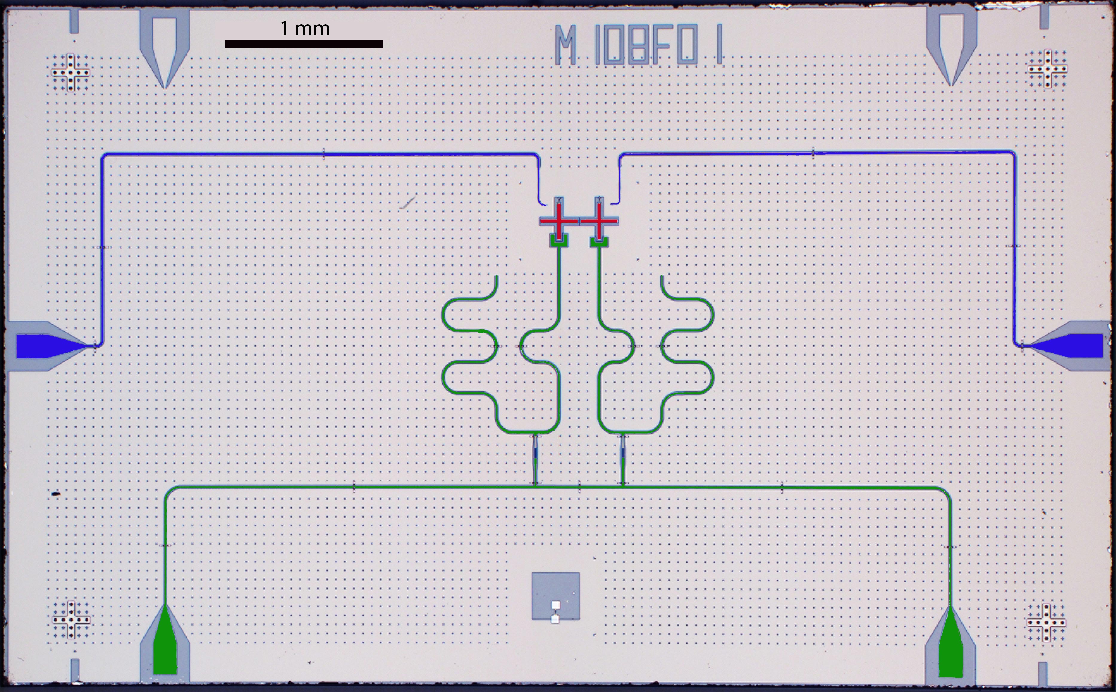
The superconducting device used in our experiment uses a frequency-tunable transmon qubit (qubit A) and a fixed-frequency transmon qubit (qubit B). The first qubit is made tunable to provide more freedom in the choice of operation frequencies, but could be at fixed frequency as well. The two qubits have frequencies GHz and GHz, energy relaxation times s and s, anharmonicities MHz and MHz, and are capacitively coupled with a coupling strength MHz, see Fig. 1(a) and (b). We control the state of each qubit using amplitude and phase modulated microwave pulses Motzoi et al. (2009); Chow et al. (2010); Gambetta et al. (2011), which are generated by upconverting the signals from an arbitrary waveform generator and applied to the qubits through a dedicated drive line. Prior to each experimental run we reset the qubits using the protocol introduced in Magnard et al. (2018), reducing the excited state populations of qubit A and B to and , respectively (see Appendix A for details).
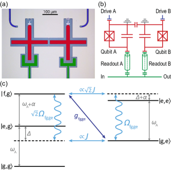
For qubit readout, two resonators at frequencies GHz and GHz are dispersively coupled to qubit A and qubit B, respectively, with strength MHz and MHz. Both resonators are coupled to a common feedline with coupling rates MHz and MHz. We determine the , , and state population of both qubits by applying two gated microwave tones to the feedline of the readout resonators at frequencies and powers optimized for qutrit readout Bianchetti et al. (2010). The transmitted signal is amplified at by a traveling wave parametric amplifier Macklin et al. (2015) and at 4 K by a high-electron-mobility transistor amplifier. At room temperature the signal is further amplified, split into two paths, which are separately down-converted using an I-Q mixer, digitized using an analog-to-digital converter, digitally down-converted and processed using a field programmable gate array Salathé et al. (2018). We extract the qutrit populations of each transmon using single-shot readout. We record each measurement trace 2000 (4000) times for all characterization (randomized benchmarking) experiments and account for readout errors Dewes et al. (2012); Kurpiers et al. (2018) (see Appendix A).
III Gate Concept
Our gate exploits a Raman transition between the two-qubit states and . The transition is analogous to the cavity-assisted Raman transition used recently for photon shaping and remote quantum communication Pechal et al. (2014); Zeytinoğlu et al. (2015); Kurpiers et al. (2018); Gasparinetti et al. (2016), qutrit reset Magnard et al. (2018); Egger et al. (2018) and two-qubit gates Egger et al. (2019), with the distinction that here the cavity is replaced by a second qubit. The coupling between and is activated by a strong microwave tone applied to the drive line of qubit A at a frequency corresponding to the energy difference between the two states, i. e. at GHz, with and the subscript ’0’ labeling the unshifted transition frequency in absence of a drive-induced ac-Stark shift on qubit . The coupling is mediated by virtual states, which are coupled to and via the drive and the direct qubit-qubit coupling , see Fig. 1(c). The two coupling paths between and indicated by the light blue arrows interfere destructively and give rise to a total coupling strength of
| (2) |
Due to the large detuning between the qubits, a large drive amplitude is required to reach a coupling strength of a few MHz and thus a gate time significantly below 1 s.
When driving the fg-ge transition for a duration which corresponds to a full round trip in the fg-ge manifold the state picks up a geometric phase of Sjöqvist (2015), thereby realizing a controlled-phase gate. Using virtual-Z gates McKay et al. (2017), this conditional phase can be assigned to either of the computational states. We perform a virtual-Z gate on qubit B, so that the state effectively picks up the phase, corresponding to flux-based implementations of controlled-phase gates which exploit the coupling between the and the state DiCarlo et al. (2009); Barends et al. (2014); Caldwell et al. (2018).
IV Gate Calibration
The fg-ge pulse is realized as a flat-top envelope with Gaussian rising and falling edges with widths ns truncated at , carrier frequency , normalized amplitude , and duration .
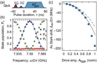
Due to the ac-Stark effect the fg-ge transition frequency depends on the drive amplitude . Similar to Magnard et al. (2018), we calibrate the ac-Stark shift by preparing the qubits in the state, applying the fg-ge pulse, and reading out the state of qubit A, see Fig. 2(a). For a given we adjust to obtain Rabi angles close to and measure the state population of qubit A as a function of frequency, see Fig. 2(b). On resonance, the population transfer from to is maximum. We fit the resulting spectrum to a Gaussian from whose center we infer the ac-Stark shift of the fg-ge transition frequency. In this way we measure the dependence of on , see Fig. 2(c). Due to the large drive amplitude, we observe deviations from a quadratic dependence Magnard et al. (2018), as discussed below.
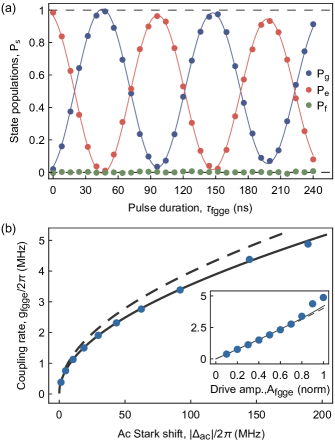
We next measure the coupling strength vs. in a Rabi experiment. For a given , we prepare , apply the fg-ge pulse at the previously determined resonance frequency for variable and measure the qutrit populations of qubit B. We fit the resulting Rabi oscillations with an exponentially decaying sinusoidal function, see Fig. 3(a) for an example with . The coupling strength is given by half of the fitted Rabi oscillation frequencies. For the largest drive amplitude we achieve a coupling strength MHz. We plot the extracted as a function of [Fig. 3(b)] rather than the voltage amplitude set at the instrument in order to be insensitive to possible nonlinearities between and the drive amplitude at qubit A, see also Appendix B.
We obtain very good agreement between data and a numerical model based on Floquet theory with independently determined parameters [solid line in Fig. 3(b)]. The model takes into account counter-rotating terms induced by the drive and the full cosine potential of the transmon qubits, see Appendix B for details. For comparison, simulations based on a rotating-wave approximation to Hamiltonian Eq. (1) fail to accurately describe our data [dashed line in Fig. 3(b)]. Due to the large drive amplitude (for we estimate ) counter-rotating terms in the Hamiltonian are important. For completeness, we also plot vs. [Fig. 3(b) inset]. For this data as well as for the data vs. presented in Fig. 2(c) we observe deviations from theory for , which we attribute to a non-linearity between and the effective drive amplitude at qubit A, see Appendix B.
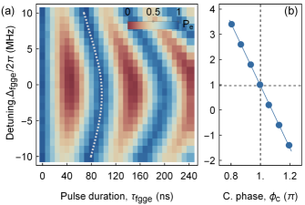
To implement a controlled-phase gate it is important to take into account the dispersive always-on coupling of the qubits. In the dispersive approximation the exchange coupling term in Eq. (1) transforms into , with Barends et al. (2014). From a Ramsey experiment we determine MHz, in agreement with the calculated value of -0.85(4) MHz and comparable to the values found in Ref. Barends et al. (2014). Hence, the state acquires not only a conditional geometric phase due to the rotation in the - subspace (assuming a virtual-Z gate on qubit B), but also a conditional dynamical phase due to the disperse always-on coupling of the qubits. As a result, has to be smaller than . Under the constraint of full population recovery into the computational subspace, this is achieved by driving the fg-ge transition slightly off-resonantly at a frequency , with the detuning between the drive and the fg-ge transition frequency, see Appendix C. We measure the corresponding Rabi oscillations as a function of for and obtain the characteristic Chevron-like pattern shown in Fig. 4(a).
While the dispersive coupling can be taken into account in the calibration of the gate, we note that it leads to coherent errors in multi-qubit settings Krinner et al. (2020). Possible mitigation strategies without compromising gate time include reducing the transversal coupling strength while increasing the drive strength, making use of dynamical decoupling techniques Viola and Lloyd (1998); Vandersypen and Chuang (2004); Bylander et al. (2011); Guo et al. (2018), combining qubits with opposite anharmonicity since Ku et al. (2020), and driving the fg-ge transition off-resonantly during idle times, which allows for adjusting and canceling the dispersive interaction Rosenblum et al. (2018).
To calibrate the controlled-phase gate we follow a two-step procedure. First, we measure the conditional phase as a function of . For this purpose, we extract the pulse durations for which qubit B is back in the state, see dashed line in Fig. 4(a). This condition corresponds to minimum level population of qubit A and therefore to maximum population recovery into the computational subspace. We then measure using a Ramsey experiment on qubit B while driving the fg-ge transition on qubit A, which is prepared in either or . The difference between the phases extracted from both measurements yields , see Fig. 4(b). From a linear fit to the data we extract the detuning MHz which yields . The second step consists of calibrating the single-qubit phases with , which are affected by the fg-ge drive induced ac-Stark effect. We measure using a Ramsey experiment on qubit in the presence of the fg-ge pulse on qubit A and correct these phases using virtual-Z gates.
V Gate Characterization
We finally characterize the gate by performing interleaved randomized benchmarking Gaebler et al. (2012); Magesan et al. (2012). We obtain a controlled-phase gate fidelity of 97.5(3)%, extracted from exponential fits of the form to the interleaved measurement and to a reference measurement, see red and blue data points in Fig. 5(a) respectively. Here, denotes the depolarizing parameter, is the number of applied two-qubit Clifford gates, and , are coefficients accounting for state preparation and measurement (SPAM) errors Magesan et al. (2012). The fidelity of the reference measurement is 94.5(1)%.
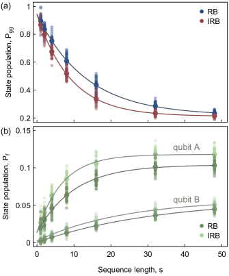
Our qutrit readout allows us to simultaneously extract the leakage rate to the level of both qubits. We fit the observed rise in level population [Fig. 5(b)] as a function of sequence length to a rate equation model Chen et al. (2016) of the form , with the initial level population, the asymptotic level population, and the sum of the leakage rate and the decay rate . Subtracting the reference leakage rate from the leakage rate of the interleaved experiment, , we extract leakage errors per controlled-phase gate of and for qubit A and B, respectively. As expected, the leakage error for qubit A is significantly larger than for qubit B because only the level of qubit A is populated during the gate.
From master equation simulations we compute an average gate fidelity of 97.5%, which is in good agreement with the measured fidelity and indicates that the gate fidelity is limited by decoherence. The numerical simulation reveal that 0.4% leakage per gate can be attributed to errors on qubit A, while the remaining leakage errors are caused by other decoherence channels. In particular, due to the dressing of the states in the driven basis, different decoherence channels can contribute. Removing transmon decoherence from master equation simulations we estimate that a gate fidelity higher than 99.9% is possible without pulse optimization.
VI Summary
In summary, we have demonstrated a fast, coherence limited all-microwave controlled-phase gate between two qubits which are detuned by about six times the qubit anharmonicity. In particular, the gate imposes no constraints on the qubit-qubit detuning and is activated by a single microwave tone applied to the drive line of one of the qubits. Hence, no further resources beyond those already used for single-qubit gates are required. We therefore believe that in future multi-qubit quantum processors our gate will provide hardware scaling advantages compared to processors relying on fast flux tunability of qubits Andersen et al. (2020) and tunable coupling circuits Arute et al. (2019). This assumes that the relatively large always-on dispersive coupling can be mitigated without large overhead Viola and Lloyd (1998); Vandersypen and Chuang (2004); Bylander et al. (2011); Guo et al. (2018); Ku et al. (2020); Rosenblum et al. (2018). Finally, the engineered coupling between and can be used in a heralded quantum communication protocol Kurpiers et al. (2019), where an auxiliary qubit indicates photon loss events.
Acknowledgements
We thank A. Akin for programming the FPGA firmware, M. Collodo for contributions to the measurement setup, C. K. Andersen and C. Eichler for discussion, and C. Le Calonnec and A. Petrescu for help with the Floquet simulations. This work was supported by the European Research Council (ERC) through the ’Superconducting Quantum Networks’ (SuperQuNet) project, by the National Centre of Competence in Research ’Quantum Science and Technology’ (NCCR QSIT) a research instrument of the Swiss National Science Foundation (SNSF), by the Office of the Director of National Intelligence (ODNI), Intelligence Advanced Research Projects Activity (IARPA), via the U.S. Army Research Office grant W911NF-16-1-0071, by the SNFS R’equip grant 206021-170731, by ETH Zürich, by NSERC, the Canada First Research Excellence Fund, and by the Vanier Canada Graduate Scholarships. S. Krinner acknowledges financial support by Fondation Jean-Jacques & Felicia Lopez-Loreta and the ETH Zurich Foundation. I. Tsitsilin acknowledges partial support from the Ministry of Education and Science of the Russian Federation in the framework of Increase Competitiveness Program of the National University of Science and Technology MISIS (Contract No. K2-2017-081). The views and conclusions contained herein are those of the authors and should not be interpreted as necessarily representing the official policies or endorsements,either expressed or implied, of the ODNI, IARPA, or the U.S. Government.
Appendix A Sample and Setup
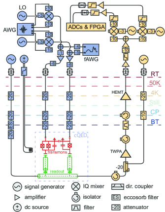
The superconducting device is made of a patterned Niobium thin film on a high-resistivity Silicon substrate using standard photolithography techniques, see Fig. 6. Josephson junctions are fabricated using electron beam lithography and shadow evaporation of aluminium with lift-off. Qubit drive and fg-ge drive signals are combined before being amplified at room temperature and routed to the dilution refrigerator. We use either single side-band modulation with IQ-mixers driven by a local oscillator (LO) and an arbitrary waveform generator (AWG), or alternatively, directly synthesized drive-pulses from a high-bandwidth AWG (fAWG).
The input lines are thermalized at each temperature stage of the dilution refrigerator and are attenuated at the 4K-, CP- and BT-stages Krinner et al. (2019). We use a superconducting coil to thread flux through the superconducting quantum-interference device (SQUID) of qubit A to tune its frequency.
The states of both transmon qubits are read out using a gated microwave tone applied to the input port of a common feed line, see Fig. 7. The output signal is routed through a circulator and a directional coupler, and amplified at with gain at and at using a traveling wave parametric amplifier (TWPA), see Fig. 7. The TWPA is pumped at a frequency of and we obtain a phase-preserving detection efficiency of for the full detection line. The signal is then further amplified by a high-electron-mobility transistor (HEMT) at and two low-noise amplifiers at room temperature. Subsequently, the signal is down-converted to using an analog mixer, lowpass-filtered, digitized by an analog-to-digital converter and processed by a field-programmable gate array (FPGA).
We extract the qutrit population of each transmon using single-shot readout with an averaged correct assignment probability of for qubit A and for qubit B. We obtain a maximal correct assignment probability with an integration time of () and a measurement power that results in a state-dependent photon number in readout resonator A (B) of 102, 2, 86 (28, 18, 29) photons for the states , , , respectively. These photon numbers are below the critical photon numbers Blais et al. (2004) for readout resonator A (B) of 223, 113 (77, 40) for the states , , respectively.
We extract the parameters of the readout circuit and the relevant coupling strengths from fits to transmission spectrum measurements. The coherence times and anharmonicity of the qutrits are determined in standard time-resolved measurements. All relevant device parameters are listed in Table 1.
| quantity, symbol (unit) | A | B |
| readout resonator frequency, (GHz) | 7.3789 | 7.0762 |
| readout resonator bandwidth, (MHz) | 0.671 | 0.633 |
| readout circuit dispersive shift, (MHz) | 0.680 | 0.280 |
| qubit transition frequency, (GHz) | 6.4961 | 4.9962 |
| transmon anharmonicity, (MHz) | -257.4 | -271.4 |
| qubit-qubit coupling strength, (MHz) | ||
| energy relaxation time on , () | ||
| energy relaxation time on , () | ||
| coherence time on , () | ||
| coherence time on , () | ||
Appendix B Calibration of AC-Stark Shift and Coupling Strength
To go beyond Eq. (2), which expresses the coupling strength as a linear function of the drive amplitude , we numerically diagonalize the system Hamiltonian in dependence on the drive amplitude. For each drive amplitude, we aim to extract both the resonant drive frequency of the fg-ge transition and the coupling strength. In order to take into account the effect of the drive and the cosine potential of the Josephson junctions fully, we model the coupled two-transmon system in the lab frame,
| (3) | ||||
where all transmon operators are taken in the charge basis, is set by the coupling capacitance between the two transmons, and and are the charging energy and Josephson energy of transmon , respectively. We consider a drive of the form , and find the resonance frequency .
We first set the drive amplitude to zero, , and choose the parameters in order to reproduce the independently extracted parameters listed in Table 1. We then perform a numerical spectroscopy experiment, and extract and for each drive amplitude following an approach similar to Ref. Zeytinoğlu et al. (2015). Essentially, we fix and scan the drive frequency , diagonalizing the Hamiltonian for different values of . We then extract and from the anti-crossing between the states closest to . We extend the numerical protocol in two major ways compared to Ref. Zeytinoğlu et al. (2015). First, we consider the Hamiltonian in the charge basis, which allows to take into account the full cosine potential of the two transmons. Due to the large drive amplitude, higher states than the state of the transmons are populated. We obtain a maximum population of the () state of 30% (6%). Modeling the system Hamiltonian in the charge basis instead of taking an anharmonic oscillator basis allows to describe these states more accurately. Second, we consider the full effect of the drive and find the Floquet eigenmodes Grifoni and Hänggi (1998) of the system in the lab frame instead of performing a rotating-wave approximation (RWA) and diagonalizing a time-independent Hamiltonian in the rotating frame of the drive. This allows to accurately describe the drive since the largest amplitudes considered here correspond to a significant fraction of the drive frequency, .
To compare the numerical curves with the experimental data, we fit an amplitude conversion factor over the small drive amplitude range . While Fig. 2(c) and the inset of Fig. 3(b) show discrepancies between the data and the numerical model for , Fig. 3(b) does not depend on the drive amplitude and shows good agreement between the numerical (black line) and experimental data (blue dots) with independently determined parameters. Considering that the simulations agree well with the experimental data when comparing quantities not sensitive to the drive amplitude, we suggest that the discrepancies observed in Fig. 2(c) and the inset of Fig. 3(b) are due to the conversion factor between and depending on frequency, i.e. .
This can be the case if the drive line of qubit A has a frequency-dependent response or if there are secondary coupling paths from the drive line to the qubit. We verified that the drive line section between the output of the arbitrary waveform generator instrument and the printed circuit board on which the chip is mounted has no frequency dependence beyond the weakly increasing attenuation as a function of frequency characteristic for semi-rigid microwave cables (see e.g. Fig. 13 a in Krinner et al. (2019)), which only explains a deviation of at maximum drive amplitude compared to its low amplitude value. However, an impedance mismatch between PCB and the on-chip part of the drive line could introduce a larger frequency dependence. Considering secondary coupling paths, it is possible that in addition to the direct coupling path from drive line to qubit A, a second path is mediated by the readout resonator of qubit A, which has a frequency GHz. The contribution of such a second path is expected to become larger as gets closer to and the effective would be given by the interference of both paths.
Appendix C Calibration of Conditional Phase
The total conditional phase accumulated during the gate is a combination of the geometric phase and the dynamical phase due to the dispersive coupling. In order to obtain a total phase of , the geometric phase should consequently be adjusted to
| (4) |
This geometric phase can be computed by considering the evolution in the effective two-level system. Denoting the effective Pauli matrices and , we write an effective two-level Hamiltonian for the driven system
| (5) |
where is the detuning between the drive and the fgge transition frequency. After a time , an initial state completes one round trip in the fg-ge manifold and accumulates a geometric phase . From Eq. (4) we then obtain that the detuning should be set to .
In the experiment, the coupling is not turned on and off instantaneously and, moreover, the dispersive coupling is altered during the gate due to the dressing between the drive and the qubit, . As a result, the detuning has to be calibrated and we find an optimal working point at MHz.
References
- Blais et al. (2020) A. Blais, A. L. Grimsmo, S. M. Girvin, and A. Wallraff, “Circuit quantum electrodynamics,” arXiv:2005.12667 (2020).
- Cross et al. (2019) Andrew W. Cross, Lev S. Bishop, Sarah Sheldon, Paul D. Nation, and Jay M. Gambetta, “Validating quantum computers using randomized model circuits,” Phys. Rev. A 100, 032328 (2019).
- Otterbach et al. (2017) J. S. Otterbach, R. Manenti, N. Alidoust, A. Bestwick, M. Block, B. Bloom, S. Caldwell, N. Didier, E. Schuyler Fried, S. Hong, P. Karalekas, C. B. Osborn, A. Papageorge, E. C. Peterson, G. Prawiroatmodjo, N. Rubin, Colm A. Ryan, D. Scarabelli, M. Scheer, E. A. Sete, P. Sivarajah, Robert S. Smith, A. Staley, N. Tezak, W. J. Zeng, A. Hudson, Blake R. Johnson, M. Reagor, M. P. da Silva, and C. Rigetti, “Unsupervised Machine Learning on a Hybrid Quantum Computer,” arXiv:1712.05771 (2017).
- Arute et al. (2019) Frank Arute, Kunal Arya, Ryan Babbush, Dave Bacon, Joseph C. Bardin, Rami Barends, Rupak Biswas, Sergio Boixo, Fernando G. S. L. Brandao, David A. Buell, Brian Burkett, Yu Chen, Zijun Chen, Ben Chiaro, Roberto Collins, William Courtney, Andrew Dunsworth, Edward Farhi, Brooks Foxen, Austin Fowler, Craig Gidney, Marissa Giustina, Rob Graff, Keith Guerin, Steve Habegger, Matthew P. Harrigan, Michael J. Hartmann, Alan Ho, Markus Hoffmann, Trent Huang, Travis S. Humble, Sergei V. Isakov, Evan Jeffrey, Zhang Jiang, Dvir Kafri, Kostyantyn Kechedzhi, Julian Kelly, Paul V. Klimov, Sergey Knysh, Alexander Korotkov, Fedor Kostritsa, David Landhuis, Mike Lindmark, Erik Lucero, Dmitry Lyakh, Salvatore Mandrà, Jarrod R. McClean, Matthew McEwen, Anthony Megrant, Xiao Mi, Kristel Michielsen, Masoud Mohseni, Josh Mutus, Ofer Naaman, Matthew Neeley, Charles Neill, Murphy Yuezhen Niu, Eric Ostby, Andre Petukhov, John C. Platt, Chris Quintana, Eleanor G. Rieffel, Pedram Roushan, Nicholas C. Rubin, Daniel Sank, Kevin J. Satzinger, Vadim Smelyanskiy, Kevin J. Sung, Matthew D. Trevithick, Amit Vainsencher, Benjamin Villalonga, Theodore White, Z. Jamie Yao, Ping Yeh, Adam Zalcman, Hartmut Neven, and John M. Martinis, “Quantum supremacy using a programmable superconducting processor,” Nature 574, 505–510 (2019).
- Kjaergaard et al. (2020a) Morten Kjaergaard, Mollie E. Schwartz, Jochen Braumüller, Philip Krantz, Joel I.-J. Wang, Simon Gustavsson, and William D. Oliver, “Superconducting qubits: Current state of play,” Annual Review of Condensed Matter Physics 11, 369–395 (2020a).
- Gambetta et al. (2017) Jay M. Gambetta, Jerry M. Chow, and Matthias Steffen, “Building logical qubits in a superconducting quantum computing system,” npj Quantum Information 3, 2 (2017).
- Barends et al. (2019) R. Barends, C. M. Quintana, A. G. Petukhov, Yu Chen, D. Kafri, K. Kechedzhi, R. Collins, O. Naaman, S. Boixo, F. Arute, K. Arya, D. Buell, B. Burkett, Z. Chen, B. Chiaro, A. Dunsworth, B. Foxen, A. Fowler, C. Gidney, M. Giustina, R. Graff, T. Huang, E. Jeffrey, J. Kelly, P. V. Klimov, F. Kostritsa, D. Landhuis, E. Lucero, M. McEwen, A. Megrant, X. Mi, J. Mutus, M. Neeley, C. Neill, E. Ostby, P. Roushan, D. Sank, K. J. Satzinger, A. Vainsencher, T. White, J. Yao, P. Yeh, A. Zalcman, H. Neven, V. N. Smelyanskiy, and John M. Martinis, “Diabatic gates for frequency-tunable superconducting qubits,” Phys. Rev. Lett. 123, 210501 (2019).
- Foxen et al. (2020) B. Foxen, C. Neill, A. Dunsworth, P. Roushan, B. Chiaro, A. Megrant, J. Kelly, Z. Chen, K. Satzinger, R. Barends, F. Arute, K. Arya, R. Babbush, D. Bacon, J. C. Bardin, S. Boixo, D. Buell, B. Burkett, Y. Chen, R. Collins, E. Farhi, A. Fowler, C. Gidney, M. Giustina, R. Graff, M. Harrigan, T. Huang, S. V. Isakov, E. Jeffrey, Z. Jiang, D. Kafri, K. Kechedzhi, P. Klimov, A. Korotkov, F. Kostritsa, D. Landhuis, E. Lucero, J. McClean, M. McEwen, X. Mi, M. Mohseni, J. Y. Mutus, O. Naaman, M. Neeley, M. Niu, A. Petukhov, C. Quintana, N. Rubin, D. Sank, V. Smelyanskiy, A. Vainsencher, T. C. White, Z. Yao, P. Yeh, A. Zalcman, H. Neven, and J. M. Martinis, “Demonstrating a continuous set of two-qubit gates for near-term quantum algorithms,” arXiv:2001.08343 (2020).
- Kjaergaard et al. (2020b) M. Kjaergaard, M. E. Schwartz, A. Greene, G. O. Samach, A. Bengtsson, M. OḰeeffe, C. M. McNally, J. Braumüller, D. K. Kim, P. Krantz, M. Marvian, A. Melville, B. M. Niedzielski, Y. Sung, R. Winik, J. Yoder, D. Rosenberg, K. Obenland, S. Lloyd, T. P. Orlando, I. Marvian, S. Gustavsson, and W. Oliver, “A quantum instruction set implemented on a superconducting quantum processor,” arXiv:2001.08838 (2020b).
- DiCarlo et al. (2009) L. DiCarlo, J. M. Chow, J. M. Gambetta, Lev S. Bishop, B. R. Johnson, D. I. Schuster, J. Majer, A. Blais, L. Frunzio, S. M. Girvin, and R. J. Schoelkopf, “Demonstration of two-qubit algorithms with a superconducting quantum processor,” Nature 460, 240–244 (2009).
- Barends et al. (2014) R. Barends, J. Kelly, A. Megrant, A. Veitia, D. Sank, E. Jeffrey, T. C. White, J. Mutus, A. G. Fowler, B. Campbell, Y. Chen, Z. Chen, B. Chiaro, A. Dunsworth, C. Neill, P. OḾalley, P. Roushan, A. Vainsencher, J. Wenner, A. N. Korotkov, A. N. Cleland, and John M. Martinis, “Superconducting quantum circuits at the surface code threshold for fault tolerance,” Nature 508, 500–503 (2014).
- Chen et al. (2014) Yu Chen, C. Neill, P. Roushan, N. Leung, M. Fang, R. Barends, J. Kelly, B. Campbell, Z. Chen, B. Chiaro, A. Dunsworth, E. Jeffrey, A. Megrant, J. Y. Mutus, P. J. J. O’Malley, C. M. Quintana, D. Sank, A. Vainsencher, J. Wenner, T. C. White, Michael R. Geller, A. N. Cleland, and John M. Martinis, “Qubit architecture with high coherence and fast tunable coupling,” Phys. Rev. Lett. 113, 220502 (2014).
- McKay et al. (2015) David C. McKay, Ravi Naik, Philip Reinhold, Lev S. Bishop, and David I. Schuster, “High-contrast qubit interactions using multimode cavity qed,” Phys. Rev. Lett. 114, 080501 (2015).
- Rol et al. (2019) M. A. Rol, F. Battistel, F. K. Malinowski, C. C. Bultink, B. M. Tarasinski, R. Vollmer, N. Haider, N. Muthusubramanian, A. Bruno, B. M. Terhal, and L. DiCarlo, “Fast, high-fidelity conditional-phase gate exploiting leakage interference in weakly anharmonic superconducting qubits,” Phys. Rev. Lett. 123, 120502 (2019).
- McKay et al. (2016) David C. McKay, Stefan Filipp, Antonio Mezzacapo, Easwar Magesan, Jerry M. Chow, and Jay M. Gambetta, “Universal gate for fixed-frequency qubits via a tunable bus,” Phys. Rev. Applied 6, 064007 (2016).
- Caldwell et al. (2018) S. A. Caldwell, N. Didier, C. A. Ryan, E. A. Sete, A. Hudson, P. Karalekas, R. Manenti, M. P. da Silva, R. Sinclair, E. Acala, N. Alidoust, J. Angeles, A. Bestwick, M. Block, B. Bloom, A. Bradley, C. Bui, L. Capelluto, R. Chilcott, J. Cordova, G. Crossman, M. Curtis, S. Deshpande, T. El Bouayadi, D. Girshovich, S. Hong, K. Kuang, M. Lenihan, T. Manning, A. Marchenkov, J. Marshall, R. Maydra, Y. Mohan, W. O’Brien, C. Osborn, J. Otterbach, A. Papageorge, J.-P. Paquette, M. Pelstring, A. Polloreno, G. Prawiroatmodjo, V. Rawat, M. Reagor, R. Renzas, N. Rubin, D. Russell, M. Rust, D. Scarabelli, M. Scheer, M. Selvanayagam, R. Smith, A. Staley, M. Suska, N. Tezak, D. C. Thompson, T.-W. To, M. Vahidpour, N. Vodrahalli, T. Whyland, K. Yadav, W. Zeng, and C. Rigetti, “Parametrically activated entangling gates using transmon qubits,” Phys. Rev. Applied 10, 034050 (2018).
- Mundada et al. (2019) Pranav Mundada, Gengyan Zhang, Thomas Hazard, and Andrew Houck, “Suppression of qubit crosstalk in a tunable coupling superconducting circuit,” Phys. Rev. Applied 12, 054023 (2019).
- Klimov et al. (2018) P. V. Klimov, J. Kelly, Z. Chen, M. Neeley, A. Megrant, B. Burkett, R. Barends, K. Arya, B. Chiaro, Yu Chen, A. Dunsworth, A. Fowler, B. Foxen, C. Gidney, M. Giustina, R. Graff, T. Huang, E. Jeffrey, Erik Lucero, J. Y. Mutus, O. Naaman, C. Neill, C. Quintana, P. Roushan, Daniel Sank, A. Vainsencher, J. Wenner, T. C. White, S. Boixo, R. Babbush, V. N. Smelyanskiy, H. Neven, and John M. Martinis, “Fluctuations of energy-relaxation times in superconducting qubits,” Phys. Rev. Lett. 121, 090502 (2018).
- Koch et al. (2007) J. Koch, T. M. Yu, J. Gambetta, A. A. Houck, D. I. Schuster, J. Majer, A. Blais, M. H. Devoret, S. M. Girvin, and R. J. Schoelkopf, “Charge-insensitive qubit design derived from the Cooper pair box,” Phys. Rev. A 76, 042319 (2007).
- Leek et al. (2009) P. J. Leek, S. Filipp, P. Maurer, M. Baur, R. Bianchetti, J. M. Fink, M. Göppl, L. Steffen, and A. Wallraff, “Using sideband transitions for two-qubit operations in superconducting circuits,” Phys. Rev. B 79, 180511 (2009).
- Chow et al. (2012) Jerry M. Chow, Jay M. Gambetta, A. D. Córcoles, Seth T. Merkel, John A. Smolin, Chad Rigetti, S. Poletto, George A. Keefe, Mary B. Rothwell, J. R. Rozen, Mark B. Ketchen, and M. Steffen, “Universal quantum gate set approaching fault-tolerant thresholds with superconducting qubits,” Phys. Rev. Lett. 109, 060501 (2012).
- Poletto et al. (2012) S. Poletto, Jay M. Gambetta, Seth T. Merkel, John A. Smolin, Jerry M. Chow, A. D. Córcoles, George A. Keefe, Mary B. Rothwell, J. R. Rozen, D. W. Abraham, Chad Rigetti, and M. Steffen, “Entanglement of two superconducting qubits in a waveguide cavity via monochromatic two-photon excitation,” Phys. Rev. Lett. 109, 240505 (2012).
- Chow et al. (2013) Jerry M Chow, Jay M Gambetta, Andrew W Cross, Seth T Merkel, Chad Rigetti, and M Steffen, “Microwave-activated conditional-phase gate for superconducting qubits,” New J. Phys. 15, 115012 (2013).
- Cross and Gambetta (2015) Andrew W. Cross and Jay M. Gambetta, “Optimized pulse shapes for a resonator-induced phase gate,” Phys. Rev. A 91, 032325 (2015).
- Egger et al. (2019) D.J. Egger, M. Ganzhorn, G. Salis, A. Fuhrer, P. Müller, P.Kl. Barkoutsos, N. Moll, I. Tavernelli, and S. Filipp, “Entanglement generation in superconducting qubits using holonomic operations,” Phys. Rev. Applied 11, 014017 (2019).
- Rigetti and Devoret (2010) Chad Rigetti and Michel Devoret, “Fully microwave-tunable universal gates in superconducting qubits with linear couplings and fixed transition frequencies,” Phys. Rev. B 81, 134507 (2010).
- Sheldon et al. (2016) Sarah Sheldon, Easwar Magesan, Jerry M. Chow, and Jay M. Gambetta, “Procedure for systematically tuning up cross-talk in the cross-resonance gate,” Phys. Rev. A 93, 060302(R) (2016).
- Brink et al. (2018) M. Brink, J. M. Chow, J. Hertzberg, E. Magesan, and S. Rosenblatt, “Device challenges for near term superconducting quantum processors: frequency collisions,” 2018 IEEE International Electron Devices Meeting (IEDM), IEE , 6.1.1–6.1.3 (2018).
- Córcoles et al. (2013) A. D. Córcoles, Jay M. Gambetta, Jerry M. Chow, John A. Smolin, Matthew Ware, Joel Strand, B. L. T. Plourde, and M. Steffen, “Process verification of two-qubit quantum gates by randomized benchmarking,” Phys. Rev. A 87, 030301 (2013).
- Motzoi et al. (2009) F. Motzoi, J. M. Gambetta, P. Rebentrost, and F. K. Wilhelm, “Simple pulses for elimination of leakage in weakly nonlinear qubits,” Phys. Rev. Lett. 103, 110501 (2009).
- Chow et al. (2010) J. M. Chow, L. DiCarlo, J. M. Gambetta, F. Motzoi, L. Frunzio, S. M. Girvin, and R. J. Schoelkopf, “Optimized driving of superconducting artificial atoms for improved single-qubit gates,” Phys. Rev. A 82, 040305 (2010).
- Gambetta et al. (2011) J. M. Gambetta, F. Motzoi, S. T. Merkel, and F. K. Wilhelm, “Analytic control methods for high-fidelity unitary operations in a weakly nonlinear oscillator,” Phys. Rev. A 83, 012308–13 (2011).
- Magnard et al. (2018) P. Magnard, P. Kurpiers, B. Royer, T. Walter, J.-C. Besse, S. Gasparinetti, M. Pechal, J. Heinsoo, S. Storz, A. Blais, and A. Wallraff, “Fast and unconditional all-microwave reset of a superconducting qubit,” Phys. Rev. Lett. 121, 060502 (2018).
- Bianchetti et al. (2010) R. Bianchetti, S. Filipp, M. Baur, J. M. Fink, C. Lang, L. Steffen, M. Boissonneault, A. Blais, and A. Wallraff, “Control and tomography of a three level superconducting artificial atom,” Phys. Rev. Lett. 105, 223601 (2010).
- Macklin et al. (2015) C. Macklin, K. O’Brien, D. Hover, M. E. Schwartz, V. Bolkhovsky, X. Zhang, W. D. Oliver, and I. Siddiqi, “A near-quantum-limited Josephson traveling-wave parametric amplifier,” Science 350, 307–310 (2015).
- Salathé et al. (2018) Yves Salathé, Philipp Kurpiers, Thomas Karg, Christian Lang, Christian Kraglund Andersen, Abdulkadir Akin, Sebastian Krinner, Christopher Eichler, and Andreas Wallraff, “Low-latency digital signal processing for feedback and feedforward in quantum computing and communication,” Phys. Rev. Applied 9, 034011 (2018).
- Dewes et al. (2012) A. Dewes, F. R. Ong, V. Schmitt, R. Lauro, N. Boulant, P. Bertet, D. Vion, and D. Esteve, “Characterization of a two-transmon processor with individual single-shot qubit readout,” Phys. Rev. Lett. 108, 057002 (2012).
- Kurpiers et al. (2018) P. Kurpiers, P. Magnard, T. Walter, B. Royer, M. Pechal, J. Heinsoo, Y. Salathé, A. Akin, S. Storz, J.-C. Besse, S. Gasparinetti, A. Blais, and A. Wallraff, “Deterministic quantum state transfer and remote entanglement using microwave photons,” Nature 558, 264–267 (2018).
- Pechal et al. (2014) M. Pechal, L. Huthmacher, C. Eichler, S. Zeytinoğlu, A. A. Abdumalikov Jr., S. Berger, A. Wallraff, and S. Filipp, “Microwave-controlled generation of shaped single photons in circuit quantum electrodynamics,” Phys. Rev. X 4, 041010 (2014).
- Zeytinoğlu et al. (2015) S. Zeytinoğlu, M. Pechal, S. Berger, A. A. Abdumalikov Jr., A. Wallraff, and S. Filipp, “Microwave-induced amplitude- and phase-tunable qubit-resonator coupling in circuit quantum electrodynamics,” Phys. Rev. A 91, 043846 (2015).
- Gasparinetti et al. (2016) Simone Gasparinetti, Simon Berger, Abdufarrukh A. Abdumalikov, Marek Pechal, Stefan Filipp, and Andreas J. Wallraff, “Measurement of a vacuum-induced geometric phase,” Sci. Adv. 2, e1501732 (2016).
- Egger et al. (2018) D.J. Egger, M. Werninghaus, M. Ganzhorn, G. Salis, A. Fuhrer, P. Müller, and S. Filipp, “Pulsed reset protocol for fixed-frequency superconducting qubits,” Phys. Rev. Applied 10, 044030 (2018).
- Sjöqvist (2015) Erik Sjöqvist, “Geometric phases in quantum information,” International Journal of Quantum Chemistry 115, 1311–1326 (2015).
- McKay et al. (2017) David C. McKay, Christopher J. Wood, Sarah Sheldon, Jerry M. Chow, and Jay M. Gambetta, “Efficient gates for quantum computing,” Phys. Rev. A 96, 022330 (2017).
- Krinner et al. (2020) S. Krinner, S. Lazar, A. Remm, C. K. Andersen, N. Lacroix, G. J. Norris, C. Hellings, M. Gabureac, C. Eichler, and A. Wallraff, “Benchmarking coherent errors in controlled-phase gates due to spectator qubits,” arXiv:2005.05914 (2020).
- Viola and Lloyd (1998) Lorenza Viola and Seth Lloyd, “Dynamical suppression of decoherence in two-state quantum systems,” Phys. Rev. A 58, 2733–2744 (1998).
- Vandersypen and Chuang (2004) L. M. K. Vandersypen and I. L. Chuang, “NMR techniques for quantum control and computation,” Rev. Mod. Phys. 76, 1037 (2004).
- Bylander et al. (2011) J. Bylander, S. Gustavsson, F. Yan, F. Yoshihara, K. Harrabi, G. Fitch, D. G. Cory, Y. Nakamura, J.-S. Tsai, and Oliver W. D., “Noise spectroscopy through dynamical decoupling with a superconducting flux qubit,” Nat. Phys. 7, 565–570 (2011).
- Guo et al. (2018) Qiujiang Guo, Shi-Biao Zheng, Jianwen Wang, Chao Song, Pengfei Zhang, Kemin Li, Wuxin Liu, Hui Deng, Keqiang Huang, Dongning Zheng, Xiaobo Zhu, H. Wang, C.-Y. Lu, and Jian-Wei Pan, “Dephasing-insensitive quantum information storage and processing with superconducting qubits,” Phys. Rev. Lett. 121, 130501 (2018).
- Ku et al. (2020) J. Ku, X. Xu, M. Brink, D. C. McKay, J. B. Hertzberg, M. H. Ansari, and B. L. T. Plourde, “Suppression of unwanted interactions in a hybrid two-qubit system,” arXiv:2003.02775 (2020).
- Rosenblum et al. (2018) S. Rosenblum, P. Reinhold, M. Mirrahimi, Liang Jiang, L. Frunzio, and R. J. Schoelkopf, “Fault-tolerant detection of a quantum error,” Science 361, 266–270 (2018).
- Gaebler et al. (2012) J. P. Gaebler, A. M. Meier, T. R. Tan, R. Bowler, Y. Lin, D. Hanneke, J. D. Jost, J. P. Home, E. Knill, D. Leibfried, and D. J. Wineland, “Randomized benchmarking of multiqubit gates,” Phys. Rev. Lett. 108, 260503 (2012).
- Magesan et al. (2012) Easwar Magesan, Jay M. Gambetta, B. R. Johnson, Colm A. Ryan, Jerry M. Chow, Seth T. Merkel, Marcus P. da Silva, George A. Keefe, Mary B. Rothwell, Thomas A. Ohki, Mark B. Ketchen, and M. Steffen, “Efficient measurement of quantum gate error by interleaved randomized benchmarking,” Phys. Rev. Lett. 109, 080505 (2012).
- Chen et al. (2016) Zijun Chen, Julian Kelly, Chris Quintana, R. Barends, B. Campbell, Yu Chen, B. Chiaro, A. Dunsworth, A. G. Fowler, E. Lucero, E. Jeffrey, A. Megrant, J. Mutus, M. Neeley, C. Neill, P. J. J. O’Malley, P. Roushan, D. Sank, A. Vainsencher, J. Wenner, T. C. White, A. N. Korotkov, and John M. Martinis, “Measuring and suppressing quantum state leakage in a superconducting qubit,” Phys. Rev. Lett. 116, 020501 (2016).
- Andersen et al. (2020) Christian Kraglund Andersen, Ants Remm, Stefania Lazar, Sebastian Krinner, Nathan Lacroix, Graham J. Norris, Mihai Gabureac, Christopher Eichler, and Andreas Wallraff, “Repeated quantum error detection in a surface code,” Nature Physics (2020).
- Kurpiers et al. (2019) P. Kurpiers, M. Pechal, B. Royer, P. Magnard, T. Walter, J. Heinsoo, Y. Salathé, A. Akin, S. Storz, J.-C. Besse, S. Gasparinetti, A. Blais, and A. Wallraff, “Quantum communication with time-bin encoded microwave photons,” Phys. Rev. Applied 12, 044067 (2019).
- Krinner et al. (2019) S. Krinner, S. Storz, P. Kurpiers, P. Magnard, J. Heinsoo, R. Keller, J. Lütolf, C. Eichler, and A. Wallraff, “Engineering cryogenic setups for 100-qubit scale superconducting circuit systems,” EPJ Quantum Technology 6, 2 (2019).
- Blais et al. (2004) Alexandre Blais, Ren-Shou Huang, Andreas Wallraff, S. M. Girvin, and R. J. Schoelkopf, “Cavity quantum electrodynamics for superconducting electrical circuits: An architecture for quantum computation,” Phys. Rev. A 69, 062320 (2004).
- Grifoni and Hänggi (1998) Milena Grifoni and Peter Hänggi, “Driven quantum tunneling,” Physics Reports 304, 229 – 354 (1998).