Role of the compensating current in the weak Josphson coupling regime: An extended study on excitonic Josephson junctions
Abstract
Huang’s experiment [Phys. Rev. Lett. , 156802 (2012)] found, in the quantum Hall bilayer of the Corbino geometry, the interlayer tunneling currents at two edges are coupled to each other and one of two tunneling currents is referred to as the compensating current of the other. The recent theoretical work [arXiv:2006.15329] has explained this exotic coupling phenomenon as a result of excitonic Josephson effect induced by interlayer tunneling current. In this paper, we study the same setup—excitonic Josephson junction— but in the weak Josephson coupling regime, which occurs for large junction length. Interestingly, we find the compensating current drives the other edge to undergo a nonequilibrium phase transition from a superfluid to resistive state, which is signaled by an abrupt jump of the critical tunneling current. We also identify the critical exponent and furthermore offer more experimental prediction.
I Introduction
Josephson effect is particularly attractive to condensed matter researchers because it serves as the striking manifestation of coherent condensation and the promising candidate for quantum technology. The unrelenting and strong attention has been received recently in optically-excited exciton or exciton-polariton cold gases Carusotto ; Shelykh ; Lagoudakis ; Rontani:PRL2010 ; Abbarchi ; Adiyatullin ; Caputo and graphene electron-hole bilayer excitonZenker ; Apinyan . However, being the best platform to achieve the exciton condensation, the quantum Hall bilayer Girvintextbook ; Eisenstein:ARCRP2014 ; Spielman:PRL2000 ; Kellogg:PRL2002 ; Tutuc:PRL2003 ; Eisenstein:Nature2004 ; Kellogg:PRL2004 ; Tutuc:PRL2004 ; Wiersma:PRL2004 ; Tiemann:NJP2008 ; Su:NatPhys2008 ; Misra:PRB2008 ; Tieleman ; Yoon ; Fink:PRL2011 ; Nandi:Nature2012 ; Nandi:PRB2013 ; Cipri ; Zhang:PRL2016 ; Barkeshli ; Sodemann ; Barkeshli ; Eisenstein:PRL2019 ; Zhu:PRB2019 ; Zhang:PRL2020 remains not studied extensively in the land of Josephson effect. Actually, the search for Josephson effect in quantum Hall bilayer ever arouse intense interest since the observation of Josephson-like tunnelingGirvin2 ; Wen4 , in which the interlayer voltage abruptly increases once exceeding a critical tunneling current Spielman:PRL2000 ; Spielman:PRL2000 ; Eisenstein:Nature2004 ; Tiemann:NJP2008 ; Misra:PRB2008 ; Yoon ; Nandi:PRB2013 . However, to the end, the Josephson-like tunneling is attributed to a mixture of coherent and incoherent interlayer tunnelingJoglekar ; Rossi ; JJSu:PRB2010 instead of the “real” Josephson effect. Once exceeding a critical current, the incoherent tunneling dominates over the coherent one.
The scattering approach by solving the Bogolubov-de Gennes HamiltonianTitov ; Dolcini ; Peotta is the standard one to explore the Josephson effect but it is difficult to access in the context of quantum Hall bilayer. In our previous worksYFHsu:SR2015 ; YFHsu:NJP2018 , we therefore turn to a new method within the frame of pseudospin dynamics based on the idea that the layers can be treated as pseudospin quantum degrees of freedomJJSu:PRB2010 ; Moon:PRB1995 ; Burkov:PRB2002 . We firstly employ this new method to study the exciton-condensate/exciton-condensate (EC/EC)YFHsu:SR2015 and exciton-condensate/normal-barrier/exciton-condensate (EC/N/EC) junctionsYFHsu:NJP2018 with a constant relative phase between two ECs that is generated by perpendicular electric fieldWen:EPL1996 . We found that excitonic Josephson effect occurs only when , where and are barrier length and correlation lengthYFHsu:SR2015 ; YFHsu:NJP2018 . When , a new transport mechanism, namely, tunneling-assisted Andreev reflection occurs at a single N/EC interfaceYFHsu:NJP2018 . While the excitonic Josephson effect gives rise to novel fractional solitonsYFHsu:SR2015 , the new mechanism leads to a half portion of fractional solitonsYFHsu:NJP2018 . Notably, these new types of solitons have potential to improve the stability and efficiency of quantum logic circuitsPegrum . We next study another setup suggested to have a relative phase by externally applying interlayer tunneling currentPark:PRB2006 .
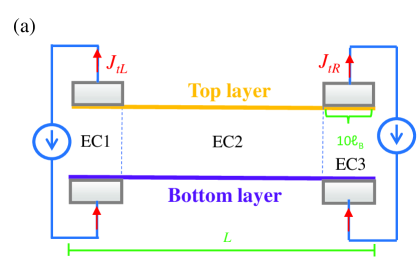
Inspired by Huang’s experimentHuang:PRL2012 , we consider the setup of interlayer tunneling currents exerted on two edges of quantum Hall bilayer as shown in Fig. 1(a). The tunneling currents (,) twist the condensate phases of two edges so as to create the relative phases between three condensates: EC1, EC2, and EC3. Such structure is regarded as two condensates (EC1 and EC3) sandwiched by a superfluid barrier (EC2), which is a type of excitonic Josephson junctionsGolubov . Ref. YFHsuPRL has explored this setup but focuses on the short junction whose junction length is smaller than Josephson length note1 . Its results demonstrated that the exotic coupling phenomenon of edge tunneling currents observed by Huang et alHuang:PRL2012 is originated from excitonic Josephson effect and Huang’s experiment is a very robust evidence for quantum Hall bilayer exciton condensation.
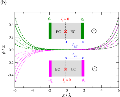
In this paper, we turn our attention to the opposite case—the long junction of , which corresponds to the typical quantum Hall bilayerHyart:PRB2011 ; Spielman:PRL2000 . Our calculation of the condensate phase [see Fig. 1(b)] reflects that the Josephson current is essentially negligible in the bulk since the phase goes to zero and becomes flat thereJs . Because the two edges are weakly Josephson coupled, the long junction can be approximated as two independent EC/EC junctions with the boundary between them occurring where Josephson current goes to zero [see the inset of Fig. 1(b)]. It is therefore highly desirable that the long junction can display entirely different properties from the short junction in which two edges are strongly Josephson coupledYFHsuPRL .
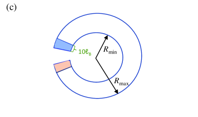
It turns out that the long junction indeed exhibits an unique property: one edge undergoes a nonequilibrium phase transitionNakamura:PRL2012 ; Matsumoto:PRD2018 with increasing the tunneling current at the other edge (i.e., the compensating current). During this phase transition, the critical tunneling current of the edge sharply falls and the corresponding critical exponent is identified as . Since the Josephson coupling is weak, we wonder why the compensating current can influence the other edge so largely? According to our analysis, this is because the compensating current reduces the effective junction length of the constituent EC/EC junction on the opposite side. We furthermore calculate the magnetic field induced by Josephson current (denoted by ) for the Corbino-geometry excitonic Josephson junction shown in Fig. 1(c). We find the length reduction effect is revealed by the crossover of the versus curve into the short junction regimeYFHsuPRL (a linear one) with increasing the compensating current, where . The induced magnetic field is estimated at pT that is large enough to be detected by the scanning superconducting interference device (SQUID). In the main body of this paper, we show the results of the rectangle-shaped junction in Figs. 3-7 while that of the Corbino-geometry junction in Figs. 8-9.
II Model and method
Burkov and MacDonald treated two layers of the quantum Hall bilayer as pseudospin quantum degrees of freedom and accordingly deduced a lattice model HamiltonianBurkov:PRB2002 :
| (1) |
Here () is the Schwinger boson creation (annihilation) operatorsLacroixtextbook where and label the site and layer indexes and is the Pauli matrix vector. The Hartree term describes the direct Coulomb interaction while the Fock term () serves the intralayer (interlayer) exchange interaction. This lattice Hamiltonian possesses eigenstate wave function which can be generally expressed as
| (2) |
The operator () creates an electron at the lattice site location in the top (bottom) layer. It is difficult to study the present issue through quantum scattering approach which is based on this wave function since we cannot simply write down the explicit forms of and .
We therefore request a SU(2) to O(3) mapping and the wave function is transformed into a classical pseudospinMoon:PRB1995
| (3) |
Accordingly, the dynamics of the quantum Hall bilayer can be described by the Landau-Lifshitz-Gilbert (LLG) equationYFHsu:SR2015 ; YFHsu:NJP2018 ; JJSu:PRB2010
| (4) |
where is the area of the unit cell for the pseudospin lattice and is the pseudospin density. The excitonic superfluid loses its coherence after traveling over one correlation length so the size of the unit cell is equal to , which is estimated at nmEastham:PRB2009 . In unit of the magnetic length , ( has the typical value of nm). On the other hand, the energy functional is composed of the capacitive penalty, the exchange correlation, and the interlayer tunneling energy, which are characterized by the parameters: anisotropic energy , pseudospin stiffness , and single-particle tunneling , respectively. These model parameters is up to which kind of samples we are discussing. The second term for the LLG equation is the Gilbert damping which relaxes the energy toward the minimum.
II.1 Modeling excitonic Josephson junctions
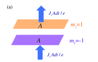
The key breakthrough of the present work is to introduce the effect of external tunneling currents. When exerting the -direction tunneling current on a area of over a short duration of , there are electrons as many as pouring out of the top layer and trickling into the bottom layer simultaneously (see Fig. 2), giving rise to the change of in the total pseudospin . Under the effect of tunneling current, the -component LLG equation thus can be modified as
| (5) |
In the rectangle-shaped excitonic Josephson junction as shown in Fig. 1(a), two tunneling current and are applied to two edges over a length as large as one lattice size 10. We can therefore model the junction through setting to
| (6) |
Notice we from here on use the continuous varying instead of the discrete for convenience in presentation and is the Heaviside step function. The origin is defined to be located at the center of the junction. After evolving with time, we ultimately acquire the static solutions for , , and that specify the pseudospin orientation. The counterflow Josephson current is furthermore calculated by
| (7) |
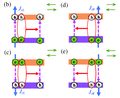
The physical picture for the effect of external tunneling currents can be depicted through Figs. 2(b)-(e). When applying the -direction tunneling current to the left edge [see Fig. 2(b)], holes and electrons are injected into the top and bottom layer from the left side, respectively. The electrons can flow into the top layer to annihilate holes via single-particle tunneling or combine with holes to form excitons and then transmit right into the junction bulk , where indicates a state composed of a hole in the top layer bound to an electron in the bottom layer. However, single-particle tunneling destroys the excitons everywhere and leads to the attenuation of counterflow Josephson current in the bulk. When reversing the direction of external tunneling current [see Fig. 2(c)], the roles of electrons and holes are exchanged and right-going but opposite polarized excitons occur, where indicates a state composed of an electron in the top layer bound to a hole in the bottom layer. Similarly, applying the ()-direction tunneling current to the right edge will generate “left”-going excitons () [see Figs. 2(d)-(e)]. It turns out that the external tunneling currents with parallel (anti-parallel) polarity will inject counterflow Josephson current in the opposite (same) direction as shown in the insets of Figs. 2(b)-(e).
II.2 Calculation of induced magnetic field due to excitonic Josephson effect
We next consider a Corbino-geometry excitonic Josephson junction that can generate circular Josephson current [see Fig. 1(c)]. The Corbino can be divided into a set of rings with radius which ranges from to . A single ring of the specific radius can be viewed as a bent Josephson junction with . We firstly calculate the phase distribution for the junction of by the LLG equation and then acquire the phase distribution for other values of by taking the azimuthal symmetry into account. The Josephson current is similarly calculated by Eq. (7). By using the Biot-Savart Law, we finally obtain the induced magnetic field:
| (8) |
where is the interlayer separation, is the distance above the center of the bilayer, and is the average over the angular axis of polar coordinate.
II.3 Choice of units, identification of critical current and determination of parameters
Both two geometries we consider are discussed based on a length scale, namely, Josephson length:
| (9) |
Two units for Josephson current and tunneling current read and throughout this paper. We identify the critical interlayer tunneling current by finding the upper and lower boundaries at which the junction departures from the coherent state, i.e., begins to become nonzero. The main focus of the present work is the typical quantum Hall bilayer of m ()Hyart:PRB2011 , which corresponds to the samples fabricated by Eisenstein’s groupSpielman:PRL2000 . Here the Coulomb interaction serves as the energy scale and meV. The other parameters we use are listed as follows: and , which were derived from the mean-field calculationHyart:PRB2011 .
III Analysis of role of the compensating current
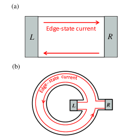
Figs. 3(a)-(b) show that edge-state currents inevitably contribute to the coupling of the left and right edges for the Hall-bar geometry while two edge-state currents separately flow along the inner and outer boundaries so as not to connect the left and right edges for the Corbino geometryFink:PRL2011 . To avoid the contribution of edge-state currents, Fig. 3(b) is the main setup we consider here and its corresponding junction length roughly approximates to the difference of the inner and outer radius. The realistic Corbino geometry possesses the junction length mmHuang:PRL2012 and in the context of the typical quantum Hall bilayerSpielman:PRL2000 (m), the junction length reads . The large part of this paper therefore focuses on the case of later.
III.1 Nonequilibrium phase transition
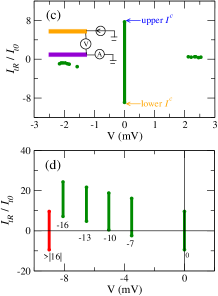
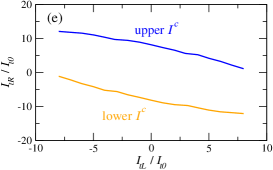
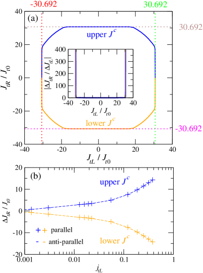
The realization of the short junction with YFHsuPRL — Huang’s experiment Huang:PRL2012 — is devoted to analyzing Josephson-like behavior, in which the interlayer voltage suddenly emerges when applying tunneling current up to critical values: the upper and lower [see Fig. 3(c)]. They found the upper and lower critical currents are correlated with its compensating current — the tunneling current exerted on the other edge and such coupling of the tunneling currents at two edges would disappear when nA [see Fig. 3(d)]. The disappearance phenomenon will be discussed later in Sec. IV.1 and we focus on how the tunneling currents at two edges correlate with each other here. Huang’s experiment quantifies this coupling through the plot of the critical currents as function of the compensating current[see Fig. 3(e)]. Therefore, we also display the similar plot for the long junction in Fig. 4 to analyze the role of the compensating current. Over a wide range of , the upper and lower critical currents nearly keep constant and are symmetric with respective to [see Fig. 4(a)]. Near , however, the critical currents rapidly fall to zero. The sharp jump of critical currents indicates the right edge is switched from a superfluid to resistive state. The right edge undergoes a phase transition under the condition of compensating-current-driven nonequilibriumNakamura:PRL2012 ; Matsumoto:PRD2018 . With slowly adjusting , it is identified as a first-order phase transition since and (The giant change in critical currents hints possible incontinuity). We furthermore define new critical exponents:
| (10) |
where . The fits to our numerical results extract the values of exponents [see Fig. 4(b)]: , for the upper curve. For the lower curve, the values of and are exactly exchanged because of electron-hole symmetry.
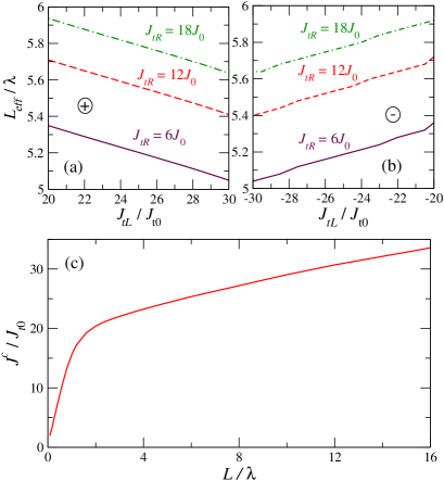
III.2 Junction-length reduction effect
Why the compensating current can largely reduce the critical currents as even if the Josephson coupling is so weak? As have been illustrated in Fig. 1(b), the long junction can be decomposed into two nearly independent EC/EC junctions. We here identify the breakpoint occurring at or where reaches its minimum and determine the effective length of the right EC/EC junction as shown in Figs. 5(a)-(b). We find, regardless of the polarity, the compensating current decreases the effective length of the right junction and hence leads to the jump of the critical currents. It is quite intuitive or shown in Fig. 5(c) that the critical current would decrease with decreasing the junction length.
IV other interesting prediction
IV.1 Discussion on Josephson breakdown effect
Now let us turn our attention to the disappearance phenomenon of the coupling of the two edge tunneling currents shown in Fig. 3(b) occurring as nA. For this disappearance phenomenon, the main body of Ref. Huang:PRL2012 furthermore demonstrates that it is accompanied with the occurrence of the interedge voltage. Ref. YFHsuPRL has attributed this phenomenon to the breakdown of Josephson effect— when Josephson current attains some critical value, the Josephson effect would collapse and the external tunneling currents will prefer to converting into edge-state currents. We here comment on whether this breakdown effect occurs also in the long junction or not. Differing from the short junction, the upper and lower curves are always symmetric with respect to as if the Josephson breakdown effect already happens and the applied compensating current is limited to a range of beyond which coherent interlayer tunneling disappears [see Fig. 4(a)]. We have performed numerical calculation demonstrating that over the range of , static solutions can exist and there was not found any critical variation. We therefore believe that the breakdown effect does not occur in the long junction.
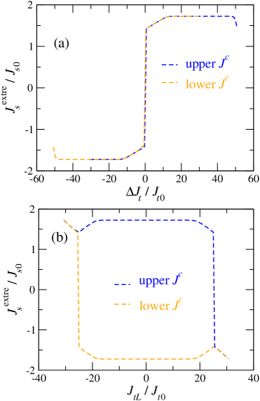
We furthermore give more detail analysis through Fig. 6. The difference of external tunneling currents plays the similar role as the relative phase in the conventional Josephson junctionGolubov while it is easier to compare with the experiment directly based on the compensating current . In Fig. 6, we therefore plot the spatial extrema of Josephson current as a function of not only but also . We find that rises or drops to saturation over the range of or [see Fig. 6(a)], which corresponds to [see Fig. 6(b)]. With increasing the compensating current, if the Josephson-breakdown regime is achieved, it necessarily occurs at where the curves hold horizontal [see Fig. 4(a)]. Measuring the interedge voltage will help us clarify the junction being in the weak Josephson coupling regime or Josephson-breakdown regime. Alternatively, after increasing the compensating current beyond , begins to fall [see Fig. 4(a)], providing an unique signature for the weakly Josephson coupling, namely, Josephson fall.
IV.2 The crossover behavior with varying junction length
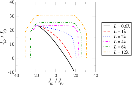
Since the dependence of the critical currents on the compensating current is so distinct for the short and long junctions, we next want to understand the crossover behavior with increasing junction length through Fig. 7. Because the lower curve can be produced through doing the electron-hole transformation: , on the upper curve, in Fig. 7, we display only the upper curve for conciseness. Fig. 7 shows that, with increasing the junction length, the curve is gradually skew and no abrupt change occurs. Moreover, the Josephson fall already can be found as while the weakly “symmetric” Josephson regime can be achieved as . The values of happens to meet the junction length for the typical quantum Hall bilayerSpielman:PRL2000 of Hall-bar geometry (m) but the Hall-bar geometry may be difficult to coincide with our calculation due to the influence of edge-state current. Replacing the usually-used side electrodes with the top and back electrodes would be a method to avoid edge-state currents although it is a big technological challenge.
IV.3 The induced magnetic field due to Josephson current in a Corbino geometry
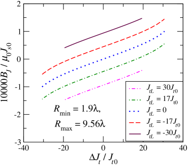
Next Fig. 8 shows the results for the Corbino-geometry excitonic Josephson junction, which is depicted in Fig. 1(c) (the curves is offset by the corresponding compensating current for clarity and a without-offset version is given in Appendix A). In Fig. 8, except for the minimum radius , the other parameters are determined according to the realistic situation of experiments. The minimum radius for the typical Corbino is roughly 0.16mm or equivalently instead of that we choose for increasing the numerical efficiency. But, the investigated Corbino of can already capture the physics of the long junction to a qualitative level and such a Corbino with smaller is easily realized by etching. We find, differing from the short junctionYFHsuPRL , the dependence of the induced magnetic field on the difference of two tunneling currents can have apparent curvature. The curve however becomes linear when reaches . This is because decreases the effective length of the EC/EC junction on the opposite side and drives the investigated Corbino into the short-junction regime of a linear dependenceYFHsuPRL . Moreover, the extremely subtle magnetic field must be measured by the scanning superconducting quantum interference device (SQUID). To our best knowledge, the resolution of the typical scanning SQUID is up to pT at a sensor-to-sample distance of nm and the current technology even improves the resolution to pTOda . We estimate on the scale pt and it is measurable without doubt.
V conclusion
In conclusion, we predict a nonequilibrium phase transition occurring in the long junction of weak Josephson coupling and find the effective length reduction effect of the compensating current. The sample size is not highly tunable in experimental measurement and therefore this length reduction effect will be largely helpful in observing the interesting crossover behavior predicted in Ref. YFHsu:NJP2018 . We furthermore discuss the possibility of the breakdown of Josephson effect and suggest measuring the interedge voltage and Josephson fallnote2 to distinguish the Josephson breakdown effect from weak Josephson coupling. We also calculate the induced magnetic field in the Corbino-geometry Josephson junction to suggest the detection of Josephson current. It should be noted that there are still very much theoretical effort called for, such as developing Bogolubov-deGennes description, exactly identifying phase transition (especially for it being first-order or second-order), systematically exploring the Josephson breakdown effect and etc. We believe the present work together with Ref. YFHsuPRL — excitonic Josephson effect induced by interlayer tunneling current —will bring new attention to the condensed matter physics community.
Acknowledge
We are grateful to W. Dietsche, A. H. MacDonald, B. Rosenstein, Jheng-Cyuan Lin, Sing-Lin Wu and Chien-Ming Tu for valuable discussion. This work were financially supported by Ministry of Science and Technology and by National Center for Theoretical Sciences of Taiwan.
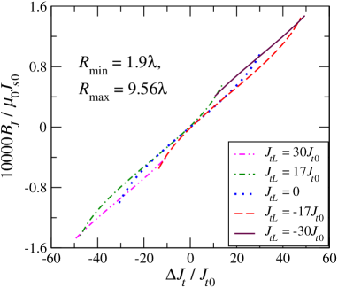
Appendix A: The without-offset version for Fig. 8
In Fig. 9, we display the original curves of Fig. 8, being not offset, to capture more definite understanding for the dependence. Similar to the short junction discussed in Ref. YFHsuPRL , the curves for different approaches each other but apparent derivation exists for large . That is to say, for the long junction, the magnitude of the induced magnetic is dependent on not only the difference of two external edge tunneling currents but also their individual values, which can be regarded as a characteristic of weak Josephson coupling. This is because in the weakly Josephson-coupled regime, the edge property becomes prominent.
References
- (1) M. Wouters and I. Carusotto, Phys. Rev. Lett. 99, 140402 (2007).
- (2) I. A. Shelykh, D. D. Solnyshkov, G. Pavlovic and G. Malpuech, Phys. Rev. B 78, 041302(R) (2008).
- (3) K. G. Lagoudakis, B. Pietka, M. Wouters, R. André, and B. Deveaud-Plédran, Phys. Rev. Lett. 105, 120403 (2010).
- (4) M. Rontani and L. J. Sham, Phys. Rev. B 80, 075309 (2009).
- (5) M. Abbarchi, A. Amo, V. G. Sala, D. D. Solnyshkov, H. Flayac, L. Ferrier, I. Sagnes, E. Galopin, A. Lemaître,G. Malpuech and J. Bloch, Nat. Phys. , 275 (2013).
- (6) A. F. Adiyatullin, M. D. Anderson, H. Flayac, M. T. Portella-Oberli, F. Jabeen, C. Ouellet-Plamondon, G. C. Sallen and B. Deveaud, Nat. Commun. 8, 1329 (2017).
- (7) D. Caputo, E. S. Sedov, D. Ballarini, M. M. Glazov, A. V. Kavokin and D. Sanvitto, Nat. Photo. , 488 (2019).
- (8) B. Zenker, H. Fehske, and H. Beck, Phys. Rev. B 92, 081111(R).
- (9) V. Apinyan and T. K. Kopeć, J. Low. Temp. Phys. 194, 325 (2019).
- (10) For a review, see S. M. Girvin and A. H. MacDonald, Perspectives in Quantum Hall Effects, edited by S. Das Sarma and A. Pinczuk (Wiley, New York,1997), Chap. V; J. P. Eisenstein, Chap. II.
- (11) For a review, see J. P. Eisenstein, Annu. Rev. Condens. Matter Phys. , 159 (2014).
- (12) I. B. Spielman, J. P. Eisenstein, L. N. Pfeiffer and K. W. West, Phys. Rev. Lett. , 5808 (2000).
- (13) M. Kellogg, I. B. Spielman, J. P. Eisenstein, L. N. Pfeiffer and K. W. West, Phys. Rev. Lett. , 126804 (2002).
- (14) E. Tutuc, S. Melinte, E. P. De Poortere, R. Pillarisetty and M. Shayegan, Phys. Rev. Lett. , 076802 (2003).
- (15) J. P. Eisenstein and A. H. MacDonald, Nature (London) , 691 (2004).
- (16) M. Kellogg, J. P. Eisenstein, L. N. Pfeiffer and K. W. West, Phys. Rev. Lett. , 036801 (2004).
- (17) E. Tutuc, M. Shayegan and D. A. Huse, Phys. Rev. Lett. , 036802 (2004).
- (18) R. D. Wiersma, J. G. S. Lok, S. Kraus, W. Dietsche, K. von Klitzing, D. Schuh, M. Bichler, H.-P. Tranitz and W. Wegscheider, Phys. Rev. Lett. , 266805 (2004).
- (19) L. Tiemann, W Dietsche, M Hauser and K von Klitzing, New J. Phys. , 045018 (2008).
- (20) J.-J. Su and A. H. MacDonald, Nat. Phys. , 799 (2008).
- (21) S. Misra, N. C. Bishop, E. Tutuc and M. Shayegan, Phys. Rev. B , 161301(R) (2008).
- (22) O. Tieleman, A. Lazarides, D. Makogon and C. Morais Smith, Phys. Rev. B , 205315 (2009).
- (23) Y. Yoon, L. Tiemann, S. Schmult, W. Dietsche, K. von Klitzing and W. Wegscheider, Phys. Rev. Lett. , 116802 (2010).
- (24) A. D. K. Finck, J. P. Eisenstein, L. N. Pfeiffer and K. W. West, Phys. Rev. Lett. , 236807 (2011).
- (25) D. Nandi, A. D. K. Finck, J. P. Eisenstein, L. N. Pfeiffer and K. W. West , Nature (London) , 481 (2012).
- (26) D. Nandi, T. Khaire, A. D. K. Finck, J. P. Eisenstein, L. N. Pfeiffer and K. W. West, Phys. Rev. B , 165308 (2013).
- (27) R. Cipri and N. E. Bonesteel, Phys. Rev. B , 085109 (2014).
- (28) D. Zhang, W. Dietsche and K. von Klitzing, Phys. Rev. Lett. , 186801 (2016).
- (29) I. Sodemann, I. Kimchi, C. Wang and T. Senthil, Phys. Rev. B , 085135 (2017).
- (30) M. Barkeshli,C. Nayak, Z. Papić, A. Young and M. Zaletel, Phys. Rev. Lett. 121, 026603 (2018).
- (31) J. P. Eisenstein, L. N. Pfeiffer and K.W. West, Phys. Rev. Lett. 123, 066802 (2019).
- (32) Z. Zhu, S.-K. Jian and D. N. Sheng, Phys. Rev. B 99, 201108(R) (2019).
- (33) D. Zhang, J. Falson, S. Schmult, W. Dietsche and J. H. Smet, Phys. Rev. Lett. 124, 246801 (2020).
- (34) For a review, see S. M. Girvin, Int. J. Mod. Phys. B , 4975 (2001).
- (35) For a review, see X. G. Wen and A. Zee, Int. J. Mod. Phys. B , 4435 (2003).
- (36) Y. N. Joglekar and A.H. MacDonald, Phys. Rev. Lett. , 196802 (2001).
- (37) E. Rossi, A. S. Núñez and A. H. MacDonald, Phys. Rev. Lett. , 266804 (2005).
- (38) J.-J. Su and A. H. MacDonald, Phys. Rev. B , 184523 (2010).
- (39) M. Titov and C. W. J. Beenakker, Phys. Rev. B 74, 041401(R) (2006).
- (40) F. Dolcini, D. Rainis, F. Taddei, M. Polini, R. Fazio and A. H. MacDonald, Phys. Rev. Lett. 104, 027004 (2010).
- (41) S. Peotta, M. Gibertini, F. Dolcini, F. Taddei, M. Polini, L. B. Ioffe, R. Fazio and A. H. MacDonald, Phys. Rev. B 84, 184528 (2011).
- (42) Y.-F. Hsu and J.-J. Su, Sci. Rep. , 15796 (2015).
- (43) Y.-F. Hsu and J.-J. Su, New J. Phys. , 083002 (2018).
- (44) K. Moon, H. Mori, K. Yang, S. M. Girvin, A. H. MacDonald, L. Zheng, D. Yoshioka and S.-C. Zhang, Phys. Rev. B , 5138 (1995).
- (45) A. A. Burkov and A. H. MacDonald, Phys. Rev. B 66, 115320 (2002).
- (46) X.-G. Wen and A. Zee, Europhys. Lett. , 227 (1996).
- (47) C. M. Pegrum, Science 312, 1483 (2006).
- (48) K. Park and S. Das Sarma, Phys. Rev. B , 035338 (2006).
- (49) X. Huang, W. Dietsche, M. Hauser and K. von Klitzing, Phys. Rev. Lett. , 156802 (2012).
- (50) Y.-F. Hsu and J.-J. Su, arXiv:2006.15329.
- (51) A. A. Golubov, M. Yu. Kupriyanov and E. II’ichev, Rev. Mod. Phys. , 411 (2004).
- (52) Josephson length is a well-known characteristic length of quantum Hall bilayer exciton condenstates. In this paper, its definition is given in Sec. II.1.
- (53) S. Nakamura, Phys. Rev. Lett. , 120602 (2012).
- (54) M. Matsumoto and S. Nakamura, Phys. Rev. D , 106027 (2018).
- (55) C. Lacroix, P. Mendels and F. Mila, Introduction to Frustrated Magnetism: Materials, Experiments, Theory (Springer, Berlin, 2011).
- (56) P. R. Eastham, N. R. Cooper and D. K. K. Lee, Phys. Rev. B , 045302 (2009).
- (57) T. Hyart and B. Rosenow, Phys. Rev. B , 155315 (2011).
- (58) This inference is based on that supercurrent is proportional to the slope of the condensate phase.
- (59) H. Oda, J. Kawai, M. Miyamoto, I. Miyagi, M. Sato, A. Noguchi, Y. Yamamoto, J. Fujihira5, N. Natsuhara6, Y. Aramaki, T. Masuda and C. Xuan, Earth, Planets and Space, 68,179 (2016).
- (60) The definition can be found in Sec. IV.1.