Spin-Lasers: Spintronics Beyond Magnetoresistance
Abstract
Introducing spin-polarized carriers in semiconductor lasers reveals an alternative path to realize room-temperature spintronic applications, beyond the usual magnetoresistive effects. Through carrier recombination, the angular momentum of the spin-polarized carriers is transferred to photons, thus leading to the circularly polarized emitted light. The intuition for the operation of such spin-lasers can be obtained from simple bucket and harmonic oscillator models, elucidating their steady-state and dynamic response, respectively. These lasers extend the functionalities of spintronic devices and exceed the performance of conventional (spin-unpolarized) lasers, including an order of magnitude faster modulation frequency. Surprisingly, this ultrafast operation relies on a short carrier spin relaxation time and a large anisotropy of the refractive index, both viewed as detrimental in spintronics and conventional lasers. Spin-lasers provide a platform to test novel concepts in spin devices and offer progress connected to the advances in more traditional areas of spintronics.
.1 1. Introduction
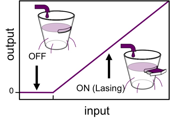
Lasers are ubiquitous devices in modern technology with applications including high-density optical storage, printing, medicine, optical sensing, and display systems Chuang:2009 ; Coldren:2012 ; Yariv:1997 ; Michalzik:2013 . Fast laser are key devices in high-speed optical interconnects and the development of even faster ones is crucial due to the expected growth in communication and data centers Michalzik:2013 ; Hecht2016:N ; Miller2017:JLT ; Miller2009:PIEEE ; Hilbert2011:S ; Jones2018:N . One of their hallmarks is the nonlinear dependence of the emitted light on pumping or injection. Two regimes (on and off) are distinguished in Fig. 1. For low carrier injection there is only sponataneous emission, the laser operates as an ordinary light source: The emitted photons are incoherent. It is the higher injection regime with stimulated emission and coherent light that makes the laser such a unique light source. The intensity of pumping/injection above which there is a phase-coherent emission of light is called the lasing threshold, , corresponding to a kink in Fig. 1.
With their highly-controllable nonlinear coherent optical response, lasers have emerged as valuable model systems to elucidate connections to other nonequilibrium and cooperative phenomena, including starting the field of synergetics Haken:1985 . The transition from an incoherent to coherent emitted light is analogous to the Landau theory of the second order phase transitions. In the analogy with ferromagnets, the dependence of spontaneous magnetization on temperature is the same as the dependence of the laser electric field on the population inversion Haken:1985 ; Degiorgio1970:PRA ; Degiorgio1976:PT .
To establish an intuitive picture of conventional lasers with spin-unpolarized carriers and, subsequently, include the influence of spin polarization in spin-lasers, we use a simple bucket model Lee2014:APL ; Lee2012:PRB , previously considered only for conventional lasers Parker:2005 . Water added to the bucket represents the injection of carriers in the laser, while the water coming out corresponds to the emitted light. The small holes represent carrier losses by spontaneous recombination and the large opening near the top depicts the lasing threshold, consistent with the operation in Fig. 1.
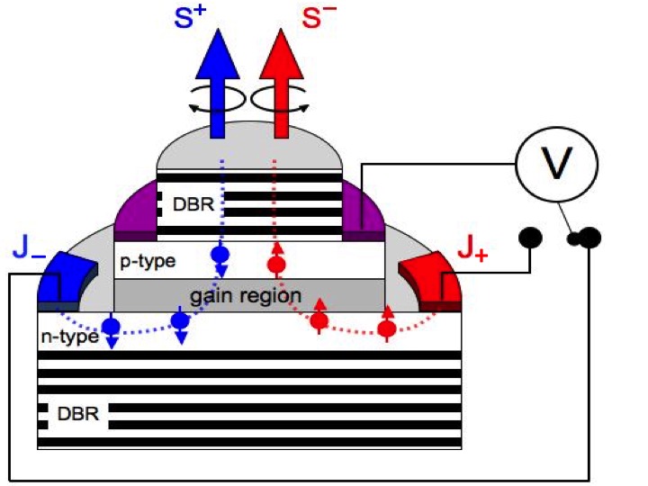
Both spin-lasers in Fig. 2 and their conventional counterparts share three main elements: (i) the active (gain) region, responsible for optical amplification and stimulated emission, (ii) the resonant cavity, and (iii) the pump, which injects (optically or electrically) energy/carriers. The main distinction of spin-lasers is the net carrier spin polarization (spin imbalance) in the active region, which leads to crucial changes in their operation. This spin imbalance is responsible for a circularly polarized emitted light, a result of the conservation of the total angular momentum during electron-hole recombination Meier:1984 ; Zutic2004:RMP . While carrier spin imbalance is typically lost within 1 ns or over m Zutic2004:RMP ; Soldat2011:APL , by being transferred to photons as circularly polarized light in spin-lasers the resulting spin-encoded signal can travel much faster and further, offering new paths for information transfer.
Most of the spin-lasers are implemented as vertical-cavity surface-emitting lasers (VCSELs) Michalzik:2013 with the gain region based on quantum wells (QWs) or quantum dots (QDs), adding to their conventional counterparts electrically or optically injected spin-polarized carriers as shown in Fig. 2. These lasers resemble common light-emitting diodes (LEDs) to which a resonant cavity is added. Another realization is the resonant cavity external to the gain device itself, using external optical elements, known as vertical-external-cavity surface-emitting lasers (VECSELs). They have complementary properties to VCSELs and may offer advantages for electrical spin injection Frougier2015:OE .
The experimental realization of spin-lasers Hallstein1997:PRB ; Ando1998:APL ; Rudolph2003:APL ; Rudolph2005:APL ; Gerhardt2006:EL ; Holub2007:PRL ; Hovel2008:APL ; Basu2008:APL ; Basu2009:PRL ; Fujino2009:APL ; Ikeda2009:IEEEPTL ; Saha2010:PRB ; Li2010:APL ; Gerhardt2011:APL ; Iba2011:APL ; Frougier2013:APL ; Frougier2015:OE ; Hopfner2014:APL ; Cheng2014:NN ; Alharthi2015:APL ; Hsu2015:PRB ; Bhattacharya2017:PRL presents two important opportunities. The lasers provide a path to practical room-temperature spintronic devices with different operating principles, not limited to magnetoresistive effects, which have enabled tremendous advances in magnetically stored information Zutic2004:RMP ; Fabian2007:APS ; Maekawa:2002 ; Parkin2004:NM ; Yuasa2004:NM ; Tsymbal:2019 ; DasSarma2000:SM ; DasSarma2001:SSC . This requires revisiting the common understanding of material parameters for desirable operation, as well as a departure from more widely studied unipolar spintronic devices, where only one type of carrier (electrons) plays an active role. In contrast, since semiconductor lasers are bipolar devices, a simultaneous description of electrons and holes is crucial. On the other hand, the interest in spin-lasers is not limited to spintronics, as they could extend the limits of what is feasible with conventional semiconductor lasers. At room temperature an order of magnitude faster operation than best conventional lasers was demonstrated in spin-lasers Lindemann2019:N , while simultaneously supporting an order of magnitude lower-power consumption. This could enable future high-performance interconnects, which is particularly important since the dominant power consumption is increasingly determined by interconnects and information transfer rather than by transistors and information processing Miller2017:JLT ; Miller2009:PIEEE ; Hilbert2011:S .
Theoretical studies of spin-lasers mostly focus only on spin-polarized electrons, the holes are merely spectators with vanishingly short spin relaxation time, losing their spin polarization instantaneously. Even simple questions remain topics of current research. Is longer spin relaxation always better? How does a simultaneous spin relaxation of electrons and holes affect the operation? Could spin-lasers inspire other device concepts in spintronics?
Following this Introduction, in Section 2 we focus on the steady-state response of spin-lasers which can be intuitively understood by the analogy with a partitioned bucket and using spin-resolved rate equations. In Section 3 we discuss dynamic response of spin-lasers and show how many trends follow from the analogy with a damped driven harmonic oscillator. In Section 4 a microscopic description of the gain region provides the connection between the electronic structure calculations, optical gain, and birefringence. While birefringence is typically considered detrimental for both conventional and spin-lasers, in Section 5 we show how strong birefringence enables ultrafast operation of spin-lasers. We conclude with some open questions and other promising implementations of spin-lasers which will closely rely on further developments in more common areas of spintronics.
.2 2. Steady-State Operation
.2.1 2a. Experimental Implementation
There are three major differences between spin-lasers and their conventional counterparts. (i) Injected carriers are spin polarized. (ii) The light emitted is circularly polarized due to the spin-polarized carriers. When an electron recombines with a hole in accordance with optical selection rules, the electron spin orientation determines the helicity (circular polarization) of the emitted photon, such that the total angular momentum is conserved. The output polarization can be controlled by adjusting either the injection polarization or its intensity. (iii) There are two lasing thresholds: Each spin feeds one corresponding mode (polarization) and the imbalance of spin-up and spin-down carrier injection leads to two separate injection (pumping) thresholds for majority, , and minority spin carriers, Gothgen2008:APL ; Lee2012:PRB .
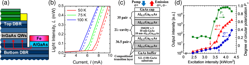
These distinguishing properties are shown in Fig. 3 for electrical Holub2007:PRL [(a), (b)] and optical injection of spin-polarized carriers Iba2011:APL [(c), (d)] to the QW gain region. Optical selection rules Meier:1984 ; Zutic2004:RMP imply that only the out-of-plane component of injected spin contributes to the emission of circularly polarized light. Since the easy axis of the magnetization usually lies in the plane of the ferromagnet, electrical spin injection then requires applying magnetic field. Zero-field spin-injection possibilities are discussed in Section 6. The threshold reduction in spin-lasers can be seen from Fig. 3(b) as the onset of lasing for solid lines is at smaller injection , than for the broken lines. Such threshold reduction, , is parametrized as,
| (1) |
where the majority spin threshold is less than the threshold without spin-polarized carriers, . Under optical excitation with positive helicity, the thresholds for emitted light of positive/negative helicity are clearly visible in Fig. 3(d) and marked by vertical arrows.
.2.2 2b. Spin-Polarized Bucket Model
To understand the trends from Fig. 3 and provide an intuitive picture of spin-lasers we invoke a bucket model shown in Fig. 4. Unlike the model in Fig. 1, the bucket is partitioned in half, while the injection/pumping is realized from two sources of hot and cold (spin up and down). The color code (red/blue) suggests that an equal mixture of hot and cold water, representing injection without spin imbalance, would recover conventional spin-unpolarized (violet) behavior of laser a from Fig. 1 as the special case.
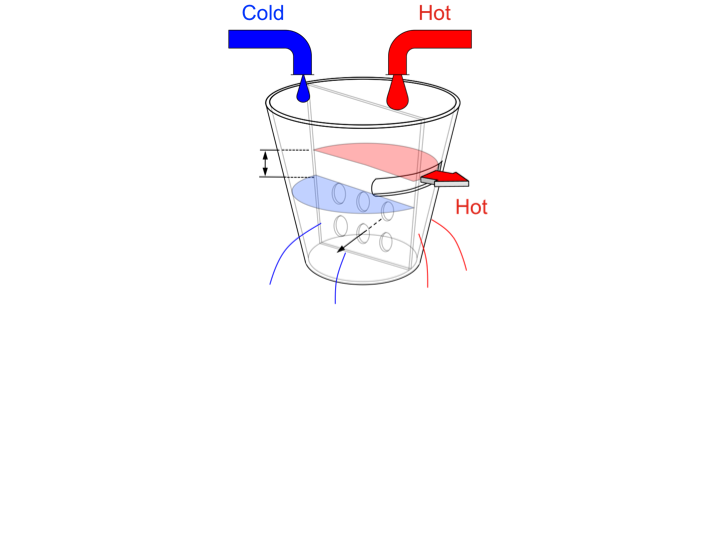
The two halves, representing two spin populations, are separately filled with hot and cold water. The openings in their partition allow mixing of hot and cold water to model the spin relaxation. With an unequal injection of hot and cold water, the injection spin polarization is,
| (2) |
where the injections of the two spin projections together comprise the total injection . The difference in the hot and cold water levels (Fig. 4) leads to the three operating regimes and () Gothgen:2010 .
At low (hot and cold water levels below the large slit), spin-up and spin-down carriers are in the off (LED) regime, thus with negligible emission. At higher , the hot water reaches the large slit and it gushes out (Fig. 4), while the amount of cold water coming out is negligible. The majority spin is lasing, while the minority spin is still in the LED regime; the stimulated emission is from recombination of majority spin carriers. Two key consequences are confirmed experimentally: (a) A spin-laser will lase at a smaller than a corresponding conventional laser (only a part of the bucket needs to be filled), there is a threshold reduction, [Eq. (1), Fig. 3(b)]. (b) Even a small can lead to highly circularly polarized light Gerhardt2006:EL ; Gothgen2008:APL . This prediction for a “spin-amplification” in the interval is demonstrated in Fig. 3(d). of only 4 % leads to the 96 % of circuular polarization of the emitted light Iba2011:APL ! gives rise to minority helicity photons from minority spin carriers, and the spin polarization of light converges to with increasing injection Gothgen2008:APL analogous to both hot and cold water gushing out. as the onset of the cold water gushing out leads to another kink in the light-injection characteristics, noticeable in solid lines for 50 K, 75 K in Fig. 3(b).
.2.3 2c. Spin-Polarized Rate Equations
Phenomenological rate equations (REs), describing the gain and the cavity region, are widely used in lasers Chuang:2009 ; Coldren:2012 . We provide their spin-resolved generalization to model the spin projection and helicity of light Lee2014:APL . For example, the electron or hole density contains the spin up (+) and down (-) parts, , , photon density is the sum of positive and negative helicities, . Allowing unequal electron and hole injections, , and spin polarizations, the generalized REs are,
| (3) | |||||
| (4) | |||||
| (5) |
In the gain term, representing the stimulated emission , is the transparency density, is the gain constant, is the gain saturation factor: the output light does not increase indefinitely with Chuang:2009 ; Coldren:2012 ; Lee1993:OQE . is the optical confinement factor. The electron spin relaxation is given by , where the electron spin relaxation time, , typically Zutic2004:RMP ; Hilton2002:PRL ; Fang2017:SR . The carrier recombination can have various dependences on carrier density, i.e., linear or quadratic (, is the bimolecular recombination coefficient) and be characterized by a carrier recombination time . is the fraction of the spontaneous recombination producing light coupled to the resonant cavity, is the photon lifetime, to model optical losses Gothgen2008:APL ; Holub2007:PRL . For an LED, the gain term vanishes and , while for VCSELs, .
Before showing how these REs reveal surprising trends in the dynamic operation of spin-lasers (Section 3) and complementing their description by a microscopic analysis of the gain term (Section 4), we use them to corroborate the picture for the steady-state operation of spin-lasers, as expected from the bucket model.
The threshold reduction is readily obtained from the steady-state solution of Eqs. (3)(5). With quadratic recombination and , , where we use threshold density for carriers, , and photons, . For , and in the limit , or, equivalently, , recall Eq. (1). As expected from the bucket model filled only with hot water and the perfect partition, we only need to fill a half of the bucket for it to overflow. In the opposite limit, , , there is no threshold reduction since the bucket partition is negligible (fast spin relaxation), we need to fill the whole bucket. In spin-lasers the electron-hole symmetry is broken, typically , with the resulting threshold Gothgen2008:APL ,
| (6) |
For and , again . Surprisingly, for , , more than expected from Fig. 4 and previously thought maximum Rudolph2003:APL ; Holub2007:PRL ; Oestreich2005:SM .
.3 3. Dynamic Operation
.3.1 3a. Harmonic Oscillator Model
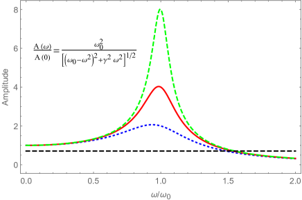
A damped driven harmonic oscillator, , provides a valuable model for the dynamic operation of lasers Lee2012:PRB , which also share its resonant behavior near the angular frequency and a large reduction of the amplitude, , for , see Fig. 5,
| (7) |
where is the angular frequency of the simple harmonic oscillator, is the damping constant, is the amplitude of the driving force and is the mass. As we will later show, reduction from by -3 dB (Fig. 5), gives a frequency range for a still substantial signal, corresponding to the modulation bandwidth of a laser Chuang:2009 ; Lee2012:PRB ; Xu2020:P .
.3.2 3b. Small Signal Analysis
The most attractive properties of conventional lasers are in their dynamic performance Chuang:2009 . Here we explore spin-polarized modulation from REs (3)(5). The model of damped driven harmonic oscillator in Section 3b is particularly useful for dynamic operation of VCSELs (recall Figs. 2, 3), the most common implementations of spin-lasers on which we focus here. External-cavity lasers (VECSELs) Alouini2018:OE and quantum cascade lasers Faist:2013 correspond to an overdamped oscillator and thus have no significant resonant behavior.
The intuition from the harmonic oscillator model gives a simple principle that lasers, as many other systems, have a frequency range over which they can follow externally imposed perturbation. For higher frequencies the laser response significantly diminishes compared to its zero-frequency response, just as we see in Fig. 5 that , and the resulting low signal to noise ratio is too small and thus limits the frequency range over which there could be a useful information transfer. Commonly, such a useful frequency range is given by the -3 dB signal reduction (see Fig. 5) and referred to as the modulation bandwidth Chuang:2009 ; Lee2010:APL .
Therefore, achieving higher modulation frequencies could enable an enhanced modulation bandwidth of a laser and thus enhanced information transfer. In the following analysis we examine if spin-polarized carriers may offer such higher modulation frequencies. Each of the key quantities, (such as, , , and ), can be decomposed into a steady-state and a modulated part , .
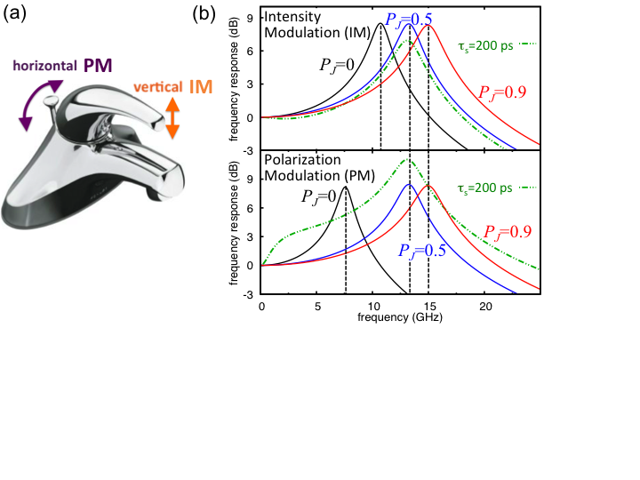
We focus on the intensity and polarization modulation (IM, PM), illustrated in Fig. 6. IM for a steady-state polarization implies (unless ),
| (8) |
where is the angular modulation frequency. Such a modulation can be contrasted with PM which also has , but remains constant const ,
| (9) |
To analyze the dynamic operation of the laser a perturbative approach to the steady-state response is commonly used and referred to as the small signal analysis (SSA), limited to a small modulation ( for IM and for PM. From REs we can obtain and the generalized (modulation) frequency response functions . In the limit they reduce to, , usually normalized to its value, just as in Eq. (7),
| (10) |
where, , is the square of the (angular) relaxation oscillation frequency and is the damping factor.
From SSA with a linear recombination, , , and for and , we obtain Lee2010:APL ,
| (11) |
where we write to recover the standard result of conventional lasers Chuang:2009 . For a steady-state spin injection and , ,
| (12) | |||||
The trends from Eqs. (11), (12) are shown in Fig. 6, with spin injection and the bandwidth exceed those in conventional lasers. (using finite and Rudolph2005:APL ; Holub2007:PRL ) show that our analytical approximations for are accurate at moderate . The increase of and the bandwidth with , for IM and PM, can be understood as the dynamic manifestation of threshold reduction with increasing . With [Eq. (12)], the situation is analogous to the conventional lasers: and the bandwidth both increase with the square root of the output power Chuang:2009 ; Yariv:1997 ( for ).
An important advantage of spin-lasers is that the increase in can be achieved even at constant input power (i.e., ), simply by increasing . A larger allows for a larger (maintaining ), which can further enhance the bandwidth, as seen in Eq. (12). For , can be up to Gothgen2008:APL .
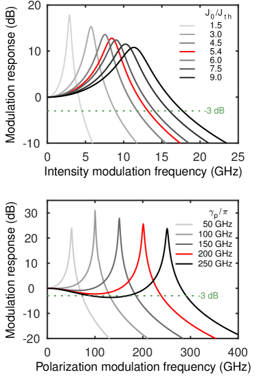
We next examine the effects of , shown for , and . IM follows a plausible trend: and the bandwidth monotonically decrease and eventually attain “conventional” values for . Surprisingly, a seemingly detrimental spin relaxation enhances the PM bandwidth and the peak in the frequency response, as compared to the long () limit Lee2010:APL ; Banerjee2011:JAP . A shorter reduces and thus the amplitude of modulated light. Since decreases faster with than , we find an increase in the normalized response function, shown in Fig. 6. The bandwidth increase comes at the cost of a reduced modulation signal.
The above trends allow us to infer some other possible advantages of PM at fixed injection. For example, such spin-lasers could reduce parasitic frequency changes, so-called chirp (-factor) Yariv:1997 , associated with the IM since leads to and, as expected from Kramers-Kroning relations, dynamically change the refractive index which influences the frequency of the emitted light Boeris2012:APL .
.3.3 3c. Large Signal Analysis
We next turn to the large-signal analysis Lee2014:APL for abrupt changes between off and on injection, , , important for high modulation frequency, short optical pulse generation, and high bit-rate in telecommunication Coldren:2012 ; Petermann:1988 . In usually employed GaAs- or InAs-based QWs, the spin relaxation times for holes are negligible. For example, at 300 K in GaAs-based QWs ps, while ps Fang2017:SR , consistent with our focus on the limit . However, our generalization to explicitly consider spin polarization of holes in RE (4) Lee2014:APL ; Wasner2015:APL and optical gain calculation FariaJunior2017:PRB (see Section 4) could be helpful for less studied gain regions based on QDs, GaN Cheng2014:NN ; FariaJunior2017:PRB , or transition metal dichalcogenides Lee2014:APL ; Mak2012:NN .
In conventional lasers a step increase in injection leads to a turn-on delay time, , required for carrier density to build up to the threshold value before light is emitted, generally detrimental for the high-speed communication. Such delay can be obtained for [see Eq. (5)] and by Petermann:1988 , for the linear recombination,
| (13) |
For the quadratic recombination Coldren:2012 ,
| (14) |
where . Another turn-on characteristic of the large-signal modulation is an overshoot of the emitted light and its damped ringing, often undesirable and implying distortion for a pulsed laser operation Coldren:2012 ; Petermann:1988 .
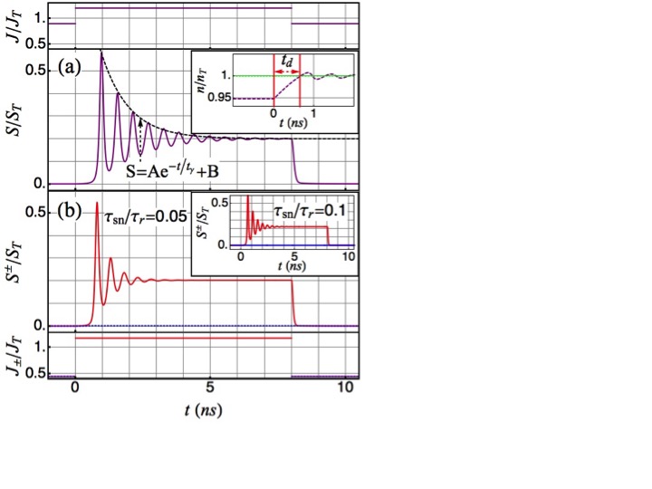
Could these turn-on characteristics be improved in spin-lasers, and what is the corresponding effect of spin relaxation time? We first examine the maximum asymmetry between the and , for optimal threshold reduction , recall Eq. (1). Our results in Fig. 7 provide a direct comparison between large-signal modulation in conventional and spin-lasers having the same on-state photon density after the end of turn-on transients. From Eqs. (13) or (14) we can also infer trends for spin-lasers: an increase in leads to the threshold reduction and thus the monotonic decrease of . These equations also apply for spin-lasers by replacing with , as long as . For a conventional laser in Fig. 7(a), ns from Eq. (14) (), or ns () obtained numerically. The delay for a spin-laser is reduced in Fig. 7(b) to ns, even for a short spin relaxation time, , and to ns for (inset).
The step-function injection causes an abrupt increase and overshoot in the photon and carrier densities. Through damped oscillations, their densities relax to the steady-state values. From ringing patterns in Figs. 7(a) and (b) we can estimate: (i) a modulation bandwidth from the corresponding relaxation oscillation frequency, 1/period of damped oscillations Petermann:1988 , and (ii) the decay time of the damped oscillations, . The ringing pattern confirms another advantage of spin-lasers: enhanced , as compared to conventional lasers (recovered for ). In Section 3b, for linear recombination, we have seen that is enhanced with the threshold reduction Lee2010:APL . For quadratic recombination from SSA with , , , we obtain Lee2014:APL ,
| (15) |
for and , respectively. These results match well the numerically extracted from a ringing pattern and confirm % bandwidth enhancement in spin-lasers. To maximize the bandwidth enhancement, comparable and are desirable, unlike when maximizing , where their asymmetry is required Gothgen2008:APL ; Lee2014:APL .
Enhancing damping in the ringing pattern is desirable for switching lasers with well-defined , values. In conventional lasers near such damping is dominated by the recombination processes and photon decay. A parametrization of this damping by [Fig. 7(a)] reveals a peculiar behavior in spin-lasers. Let us focus on the case. The damping is enhanced by the spin relaxation due to : a shorter provides a stronger damping. However, spin-lasers reduce to conventional lasers for ; the injected spin polarization is immediately lost and the damping mechanism from spin relaxation is suppressed. Comparing then Fig. 7(a) [viewed as the spin-laser with ] with Fig. 7 (b) and its inset confirms the nonmonotonic damping of ringing.
This surprising nonmonotonic dependence of can be explained in analogy with Matthiessen’s rule for different scattering mechanisms Lee2014:APL . It is instructive to view the effective decay as an interplay of the spin-independent and spin-dependent part: . Similarly, it is customary to express Coldren:2012 the carrier lifetime as a combination of radiative (R) and nonradiative (NR) contributions: . In the limit of , the spin contribution vanishes () and ns, as in the conventional lasers Lee2014:APL . For the maximum decay the two contributions should be comparable: . Turning now to the case of , we infer an additional hole-spin contribution , which leads to even smaller .
Our laser analysis with the explicit inclusion of spin relaxation times for both electrons and holes reveals that optimizing the performance in spintronic devices is much more complex than simply requiring suppressed spin relaxation. Since the spin relaxation times for a given material could be readily changed by an applied magnetic and even electric field Zutic2004:RMP , it is possible to test some of our predicted trends in already fabricated spin-lasers.
.4 4. Microscopic Description
To better understand the operation of spin-lasers and how their performance could exceed that of best conventional lasers it is important to complement their RE description with a microscopic picture. We focus on the gain region which usually includes III-V QWs or QDs. At the level of REs, there is an effective mapping Lee2012:PRB ; Oszwaldowski2010:PRB , between QW- and QD-based lasers Basu2008:APL ; Basu2009:PRL ; Saha2010:PRB .
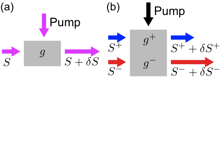
.4.1 4a. Optical Gain
The key effect of the gain region is to produce a stimulated emission and coherent light that makes the laser such a unique light source. The corresponding optical gain that describes stimulated emission, under sufficiently strong pumping/injection of carriers, can be illustrated in Fig. 8. Neglecting any loses in the resonant cavity, such a gain provides an exponential growth rate with the distance across a small segment of gain material Coldren:2012 . Since both static and dynamic operations of spin-lasers crucially depend on their corresponding optical gain, we consider its microscopic description derived from an accurate electronic structure of an active region.
.4.2 4b. Theoretical Framework
We focus here on the QW implementation also found in most of the commercial VCSELs Michalzik:2013 . To obtain an accurate electronic structure in the active region, needed to calculate optical gain, we use the method Cardona:2010 ; FariaJunior2015:PRB . Previous calculations were performed using method in which the electronic structure for conduction and valence bands is assumed decoupled Holub2011:PRB . The total Hamiltonian of the QW system, with the growth axis along the direction, can be written as,
| (16) |
where denotes the term, describes the strain term, and includes the band-offset at the interface that generates the QW energy profile.
Considering that common nonmagnetic semiconductors are well characterized by the vacuum permeability, , a complex dielectric function , where is the photon (angular) frequency, can be used to simply express the dispersion and absorption of electromagnetic waves. The absorption coefficient describing gain or loss of the amplitude of an electromagnetic wave propagating in such a medium is the negative value of the gain coefficient (or gain spectrum) Chuang:2009 . This gain coefficient corresponds to the ratio of the number of photons emitted per second per unit volume and the number of injected photons per second per unit area, therefore having a dimension of 1/length, it can be expressed as,
| (17) |
where is the speed of light, is the dominant real part of the refractive index of the material Haug:2004 and is the imaginary part of the dielectric function which generally depends on the polarization of light, , given by
| (18) |
where the indices (not to be confused with the speed of light) and label the conduction and valence subbands, respectively, is the wave vector, is the interband dipole transition amplitude which is directly calculated using wave functions, is the Fermi-Dirac distribution for the electron occupancy in the conduction (valence) subbands, is the Planck’s constant, is the interband transition frequency, and is the Dirac delta-function, which is often replaced to include broadening effects for finite lifetimes Chuang:2009 ; Chow:1999 . From the previous studies of conventional lasers, excluding spin injection, such broadening effects are known to improve Chow:1999 the free-carrier gain model we employ here. For a full microscopic description and quantitative accuracy, one would also need to include many-body effects Chow:1999 and generalize them to spin-lasers. The constant is , where is the electron charge, is the free electron mass, and is the QW volume.
Using the dipole selection rules for the spin-conserving interband transitions, the gain spectrum,
| (19) |
can be expressed in terms of the contributions of spin up and down carriers. To obtain , the summation of conduction and valence subbands is restricted to only one spin: and in Eq. (18).
To see how spin-polarized carriers could influence the gain, we show chemical potentials, , for a simplified conduction (valence) band in Fig. 9(a). To consider the spin imbalance in the active region, we introduce ,
| (20) |
where is the energy, is density of states in the conduction band for the respective spin FariaJunior:2016 , is the Boltzmann constant, and the absolute temperature. Unlike the conventional chemical potential, cannot be determined independently because each band does not contain pure spin states, but mixed states. However, when the spin mixing is not significant, we could assume that are almost independent. Similarly, one can introduce , but we mostly consider that holes are not spin-polarized, .
Such different chemical potentials lead to the dependence of gain on the polarization of light, described in Fig. 9(b). Without spin-polarized carriers, the gain is the same for and helicity of light. In an ideal semiconductor laser, requires a population inversion for photon energies, . However, a gain broadening is inherent to lasers and, as depicted in Fig. 9(b), even below the bandgap, . If we assume and (accurately satisfied, as spins of holes relax much faster than electrons), we see different gain curves for and . The crossover from emission to absorption is now in the range of () and ().
For our microscopic description of spin-lasers we focus on a (Al,Ga)As/GaAs-based active region, a choice similar to many commercial VCSELs. We consider an barrier and a single 8 nm thick GaAs QW. The corresponding electronic structure of both band dispersions and the density of states (DOS) is shown in Fig. 10. Our calculations, yield two confined CB subbands: CB1, CB2, and five VB subbands, labeled in Fig. 10(a) by the dominant component of the total envelope function at , heavy and light holes (HH, LH). The larger number of confined VB subbands (with lifted HH/LH degeneracy) stems from larger effective masses for holes than electrons. These differences in the effective masses also appear in the DOS shown in Fig. 10(b).
To describe the gain spectrum, once we have the electronic structure, it is important to understand the effects associated with carrier occupancies through injection/pumping. The carrier population Coldren:2012 is given using the product of the Fermi-Dirac distribution and the DOS for CB and VB for both spin projections.
.4.3 4c. Spin-Dependent Gain and Birefringence
From the conservation of angular momentum and polarization-dependent optical transitions we can understand that even in conventional lasers carrier spin plays a role in determining the gain. However, in the absence of spin-polarized carriers (without a magnetic region or an applied magnetic field), the gain is identical for the two helicities: , and we recover a simple description (spin- and polarization-independent) from Fig. 8(b). In our notation, , the upper (lower) index refers to the circular polarization (carrier spin) [recall Eq. (19)].
This behavior can be further understood from the gain spectrum in Figs. 11(a) and (b), where we recognize that requires: (i) and , dominated by CB1-HH1 () and CB1-LH1 () transitions, respectively (recall Fig. 10). No spin-imbalance implies spin-independent and [Fig. 9(a)] and thus , , and , all vanish at the photon energy E. Throughout our calculations we choose a suitable broadening Chow:1999 , which accurately recovers the gain of conventional (Al,Ga)As/GaAs QW systems.
We next turn to the gain spectrum of spin-lasers. Why is their output different for and light, as depicted in Fig. 8(b)? Changing only from Figs. 11(a) and (b), we see very different results for and light in Figs. 11(c) and (d). implies that , leading to a larger recombination between the spin up carriers () and thus to a larger for and (red/dashed line) than (blue/dashed line). The combined effect of having spin-polarized carriers and different polarization-dependent optical transitions for spin up and down recombination is then responsible for , given by solid lines in Figs. 11(c) and 11(d). For this case, the emitted light exceeds that with the opposite helicity, , there is a gain asymmetry (also known as the gain anisotropy) Holub2007:PRL ; Hovel2008:APL ; Basu2009:PRL , another consequence of the polarization-dependent gain. The gain asymmetry is crucial for spin-selective properties of lasers, including robust spin-filtering or spin-amplification, in which even a small (few percent) in the active region leads to an almost complete polarization of the emitted light (of just one helicity) Iba2011:APL . Interestingly, with simultaneous polarization of electrons and holes, which could be feasible for GaN-based lasers, such gain asymmetry can even change the sign by simply changing the total carrier density FariaJunior2017:PRB .
The zero gain is attained at for spin up (red curves) and for spin down transitions (blue curves). The total gain, including both of these contributions, reaches zero at an intermediate value. Without any changes to the band structure, a simple reversal of the carrier spin-polarization, , reverses the role of preferential light polarization.
An important implication of an anisotropic dielectric function is the phenomenon of birefringence in which the refractive index, and thus the phase velocity of light, depends on the polarization of light Coldren:2012 . Due to phase anisotropies in the laser cavity and the polarization-dependence of the refractive index, the emitted frequencies of linearly polarized light in the x- and y-directions ( and ) are usually different. Such birefringence is often undesired in conventional lasers since it is the origin for the typical complex polarization dynamics and chaotic polarization switching behavior in VCSELs SanMiguel1995:PRA ; vanExter1997:PRB ; Sondermann2004:IEEE ; Virte2013:NP ; Al-Seyab2011:IEEEPJ . While strong values of birefringence are usually considered to be an obstacle for the polarization control in spin-polarized lasers Hovel2008:APL ; Frougier2015:OE ; Yokota2017:IEEEPTL ; Fordos2017:PRA , the combination of a spin-induced gain asymmetry with birefringence in spin-VCSELs allows us to generate fast and controllable oscillations between and polarizations Gerhardt2011:APL ; Hopfner2014:APL . The frequency of these polarization oscillations is determined by the linear birefringence in the VCSEL cavity and can be much higher than . This opens the path towards ultrahigh bandwidth operation for optical communications Lee2014:APL ; Gerhardt2011:APL ; Lindemann2019:N ; Gerhardt2012:AOT , demonstrated in Section 5.
In order to investigate birefringence effects in the active region of a conventional laser, we consider uniaxial strain by extending the lattice constant in x-direction. For simplicity, we assume the barrier to have the same lattice constant as GaAs, , in y-direction. For we have the corresponding element of the strain tensor , while gives . Besides the differences induced in the band structure, the uniaxial strain also induces a change in the dipole selection rules between and light polarizations, which can be seen in the gain spectra .
To calculate the birefringence coefficient in the active region, we use the definition Mulet2002:IEEEJQE ,
| (21) |
where is the frequency of the longitudinal mode in the cavity, the effective index of refraction of the cavity and the group refractive index. For simplicity, we assume . The real part of the dielectric function can be obtained from the imaginary part using the Kramers-Kronig relations Chuang:2009 . We consider three resonant cavity positions: , , (vertical lines in Fig. 12), defining the corresponding energy of emitted photons eV (CB1-HH1 transition), eV (CB1-LH1 transition) and (at the high energy side of the gain spectrum) and include four carrier densities.
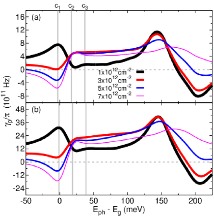
We present the birefringence coefficient in Fig. 12(a) and 12(b) for and , respectively. This strain in the active region is responsible for modest changes in bandgap (from 1.483 eV to 1.481 eV) and the gain spectra FariaJunior2015:PRB . However, it also produces birefringence values of the order of Hz which can be exploited to generate fast polarization oscillations Lindemann2019:N . Increasing the strain amount by from case (a) to case (b), the value of increases by approximately 3 times. We also included in our calculations spin-polarized electrons and notice that they have only a small influence in the birefringence coefficient. Although they slightly change and , the asymmetry is not affected at all for small of 10-20 %, relevant values in real devices. Comparing different cavity designs we observe that for , the value of strongly decreases and also changes sign with the carrier density, . In contrast, for and , is always positive. For large anisotropies in the DBR, the birefringence coefficient is on the order of Hz, consistent with the measurements given in Ref. vanExter1997:PRB . For the investigated strain conditions, the main contribution to comes from the active region and it is a very versatile parameter that can be fine-tuned using both carrier density and cavity designs, possibly even changing its sign and reaching carrier density-independent regions FariaJunior2015:PRB .
Even though many-body effects have not been included in the studies of highly-birefringent spin-lasers, some guidance of their influence is available from conventional lasers. For example, we expect band-gap renormalization and Coulomb enhancement which typically lead to the red shift and enhancement of the gain spectra with the threshold reduction, as compared to the results from the free-career model Haug:2004 ; Chow:1999 ; Burak2000:PRA ; Burak2000:IEEEJQE . However, comparing many-body and free-career models in conventional lasers reveals only a moderate change in the calculated birefringence Burak2000:PRA . This suggests that our description of spin-lasers can provide valuable guidance in exploring birefringence, while in Section 5 we discuss the inclusion of other optical anisotropies.
.5 5. Ultrafast Spin-Lasers
.5.1 5a. Birefringent Spin-Lasers
That the coupling between the spins of carriers and photons could support a high-frequency operation of lasers was already realized in the first VCSEL with optical spin injection Hallstein1997:PRB . The transfer of a coherent Larmor precession of the electron spin to the spin of photons was shown to support polarization oscillation of the emitted light up to 44 GHz in an external magnetic field of 4 T at 15 K Hallstein1997:PRB . While this approach is limited to cryogenic temperatures and does not allow an arbitrary modulation of the polarization, which would be important for high-speed communication, nor it is clear if the resulting modulation bandwidth (see Sections 3a and 3b) could exceed those of conventional lasers, it has motivated other implementations of spin-lasers.
An improved dynamical operation of spin-lasers can be seen from our predictions Lee2010:APL in Section 3b. With spin injection there is a threshold reduction which enhances the resonance (relaxation-oscillation) frequency for intensity modulation (IM) from Eq. (12), and, as in conventional lasers Chuang:2009 , enhancing the usable frequency range, given by the modulation bandwidth (see Fig. 5),
| (22) |
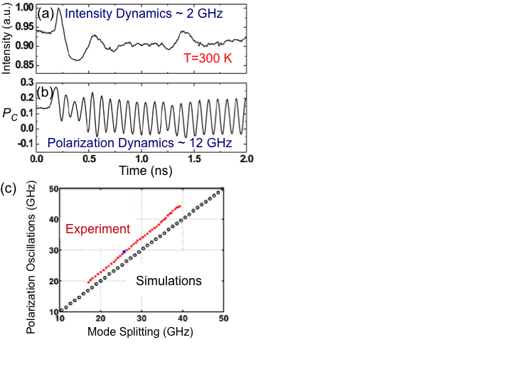
In contrast, an enhanced dynamical operation, not relying on a threshold reduction, has been demonstrated by using existing birefringence in commercial VCSELs Gerhardt2011:APL ; Li2010:APL . A comparison of Figs. 13(a) and (b) shows that polarization dynamics can be much faster than intensity dynamics for a GaAs-QW VCSEL in which circularly polarized light was used to generate spin-polarized carriers. Since the birefringence is responsible for the beating between the emitted light of different helicities, the changes in the polarization of the emitted light,
| (23) |
can be faster than the changes in the light intensity.
Even though these experiments have not reached GHz in the best commercial semiconductor lasers Haghighi2018:ISLC , together with theoretical predictions suggesting strain-enhanced much higher operation frequency in Section 4c FariaJunior2015:PRB , they provide the proof of concept that birefringence can be useful. Subsequently, anisotropic strain was induced into the cavity by pressing a sharp tip close to the gain region Lindemann2016:APL . The corresponding results in Fig. 13(c) confirm that oscillation frequency of the grows with the increase of birefringence, responsible for the mode splitting, up to 44 GHz, comparable to the fastest . Even though only supporting static implications of birefringence due to mode splitting, discussed further below, alternative paths have shown even higher birefringence values using the elasto-optic effect up to GHz Panajotov2000:APL , asymmetric heating up to GHz Pusch2017:APL , integrated surface gratings up to 98 GHz Pusch2019:EL , and mechanical bending reaching 259 GHz Pusch2015:EL .
While these experiments on high birefringence are encouraging, it is important to recognize several key requirements for implementing ultrafast lasers. To demonstrate that birefringent spin-lasers are indeed suitable for ultrafast polarization modulation and data transmission, four major challenges had to be overcome: (1) implementing a large birefringence splitting; (2) proving that birefringence can control the polarization oscillation frequency; (3) demonstrating that polarization dynamics in spin-lasers can be as fast as hundreds of GHz, faster than other state-of-the-art concepts for direct laser modulation; and (4) verifying its capability for optical data communication, including a large modulation bandwidth. For a practical implementation it is also important to establish a low-power consumption.
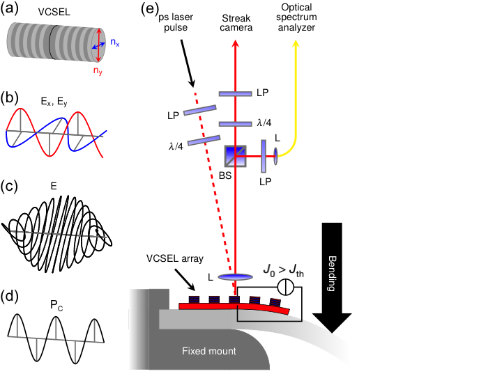
Remarkably, with a highly-birefringent AlGaAs-based 850 nm VCSEL, depicted in Fig. 14, all these challenges can be addressed, unlike the common expectations that birefringence is detrimental in conventional and spin-lasers Hovel2008:APL ; Frougier2015:OE ; Yokota2017:IEEEPTL ; Fordos2017:PRA . We demonstrate room-temperature polarization oscillations (PO) with GHz, resulting in a polarization modulation (PM) bandwidth GHz, an order of magnitude larger values than in the best conventional lasers. This operation is achieved using a hybrid pumping scheme of a constant electrical injection of spin-unpolarized carriers above the threshold injection and a ps laser pulse serving as spin injection. The laser pulse becomes circularly polarized after passing through the linear polarizer and the quarter-wave plate, which excites spin-polarized carriers in the gain region.
The cavity anisotropy of the considered VCSELs is responsible for the linear birefringence, (recall Section 4c), manifested in (i) linearly polarized emission due to anisotropy of the refractive index , sketched in Fig. 14(a) and (ii) the frequency of mode splitting,
| (24) |
of the two orthogonal modes, described by electric fields Ex, Ey in Fig. 14(b), where is the linewidth enhancement factor, and is the dichroism, which represents the anisotropy of absorption (or, equivalently, of optical gain). A usually weak coupling between the two modes results in an unstable behavior with polarization switching and related to the beat frequency between the Ex and Ey and leads to the periodic evolution of the total electric field, E=Ex+Ey, shown in Fig. 14(c). The resulting can be controlled by PM, discussed in Eq. (9).
By generalizing a model for conventional VCSELs and the rate equations (3)(5) to include the effects of optical anisotropies, as discussed in Section 5b, our theoretical analysis reveals that the PO has a resonant behavior similar to the intensity oscillation in conventional VCSELs, but with a different frequency,
| (25) |
where and are the carrier recombination and spin-flip rates, the linewidth enhancement factor, is the phase-related saturation and , as in Section 3b, is the steady-state photon density normalized to its value at 2. For a large Eq. (25) is valid for all practical pumping regimes, while the last two terms are negligible compared with . Thus a strongly enhanced birefringence, , may overcome the frequency limitations of conventional lasers.
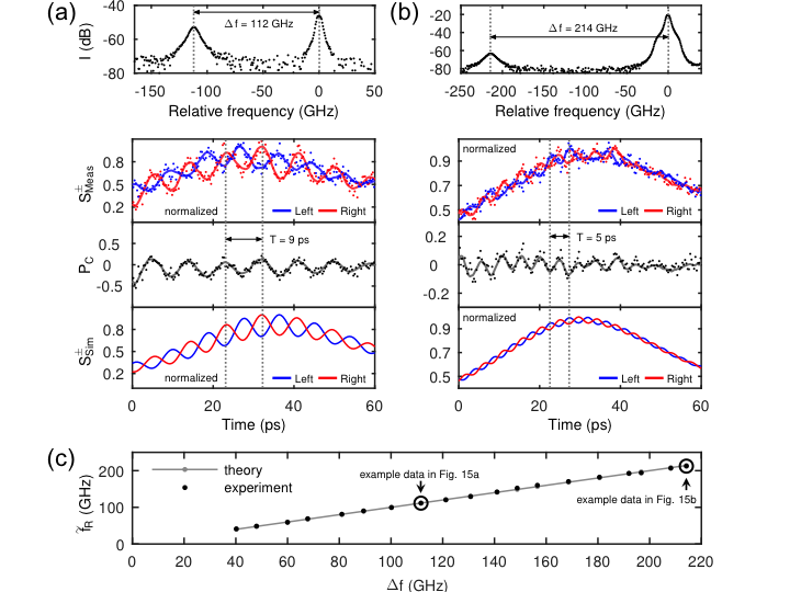
Our results from the measurement setup in Fig. 14(b) are shown for GHz ( GHz, approaching damage threshold) in Figs. 15(a) and 15(b). In the polarization-resolved measured and simulated normalized intensities and , the slow envelope is the second peak of the intensity relaxation oscillation after excitation. Its frequency is GHz for both datasets. In , the overlaying intensity dynamics vanishes and only the fast PO is evident, showing GHz or GHz . The polarization dynamics is more than an order of magnitude faster than the intensity dynamics in the same device!
The PO amplitude is decreasing with increasing frequency, both due to the bandwidth of the measurement system and due to fundamental limitations of the polarization dynamics including dichroism, spin-flip rate, and pumping current. By changing with bending, as depicted in Fig. 14(d), is continuously tuned up to 212 GHz, showing an excellent agreement with the theoretical calculation over the entire frequency range in Fig. 15(c).
For a regime in which the optical anisotropies are dominated by , we can approximate Eqs. (24) and (25) as, . While numerically and are closely related, they refer to static () and dynamic regime (). Therefore, there is a crucial difference between the static response of birefringence, visible as mode splitting in the spectrum of the laser emission reported in Ref. Pusch2015:EL , and the possibility of achieving high-frequency operation of a spin-VCSEL discussed here.
.5.2 5b. Generalized Spin-Flip Model
To study the dynamics of highly-birefringent spin-lasers it is important to consider optical anisotropies missing in Eqs. (3)(5). A suitable starting point is the spin-flip model SanMiguel1995:PRA ; Al-Seyab2011:IEEEPJ ; Alharthi2015:APL , initially used to study dynamical operation and linear polarization switching in conventional VCSELs SanMiguel1995:PRA . The framework for this model comes from the Maxwell-Bloch equations Haug:2004 ; Chow:1999 ; SanMiguel1995:PRA ; Fordos2017:PRA ; Mulet2002:IEEEJQE ; Burak2000:PRA ; Burak2000:IEEEJQE ; Hess1996:PRA ; Bowden1993:OC which describe interaction between the gain medium and electromagnetic field within the dipole approximation for optical transitions by relating electric field, polarization, and carrier densities. However, for spin-lasers various generalizations of the spin-flip model SanMiguel1995:PRA are needed, such as including unequal spin-relaxation rates for electrons and holes, as in Section 2c. Unlike the photon densities (intensities) used in (3)(5), the spin-flip model is described with normalized helicity amplitudes of the electric field, , where . The resulting equations are Lindemann2019:N ,
| (26) | |||||
| (27) | |||||
| (28) | |||||
where are slowly varying amplitudes of the electric field, and retain the meaning from Eqs. (3)(5), while , , , , and were introduced in Eqs. (24) and (25). is the total population inversion of laser upper and lower levels, is the population difference between spin-down and spin-up electrons with a decay rate , see Eq. (3). The relation between the and the spin polarization of recombining carriers is given by the standard dipole selection rules in semiconductors. Since holes typically have a negligibly short , only the electrons are considered spin-polarized, see Section 2c.
In the standard spin-flip model SanMiguel1995:PRA , the polarization of the active region material was assumed to respond linearly to E, but that fails to describe our experimental observations. Therefore we consider a generalized nonlinear response such that the saturation effects are included and polarization . Here, an intensity-dependent part with a complex coefficient is subtracted from the linear susceptibility to quantify saturation effects associated with amplitude and phase of the field, respectively. This leads to the additional term in Eq. (26) in comparison to the model used in Ref. SanMiguel1995:PRA .
For our dynamic simulations using the generalized spin-flip model, the values for important parameters, such as the gain anisotropy, have been extracted from a series of experimental measurements Lindemann2019:N . Thus, direct influence of the Coulomb interaction on the steady-state parameters are effectively considered.
.5.3 5c. Ultrafast Modulation Response
The demonstrated record-high PO frequency in Fig. 15 provides the basis to evaluate the performance of spin-lasers for digital optical communication, characterized by the modulation bandwidth (see Section 3b) and data transfer rates, commonly analyzed using so-called eye diagrams Wasner2015:APL ; Lindemann2019:N . Modulation bandwidth and data transfer rates are modeled using the methods from Section 5b with a parameter set carefully obtained from the experiments. The IM, given in Fig. 16(a) by the response function , similar to Section 3b, resembles the displacement of a harmonic oscillator from Fig. 5. The bandwidth given by in Eq. (22) is enhanced, just as , by the increasing photon density through increased pumping current. In our experiments, the pumping current of 5.4 corresponds to GHz, while GHz for all pumping rates . Remarkably, for the same device parameters, Fig. 16(b) reveals
a huge increase in the PM bandwidth from the response function . Similar to in Eq. (25), the corresponding bandwidth increases with .
While readily available excitation pulses can trigger the PO observed in Fig. 15, experimental demonstration of a huge increase in the PM bandwidth from Fig. 16 is much more challenging. For that purpose a spin-VCSEL is modulated using a semiconductor laser diode with a continuous wave operation and an additional PM setup containing an electrooptic modulator. The maximum modulation is limited by the modulator to GHz, the fastest available commercial device at the considered frequency for our AlGaAs lasers. With this set-up is modulated, while the intensity stays constant.
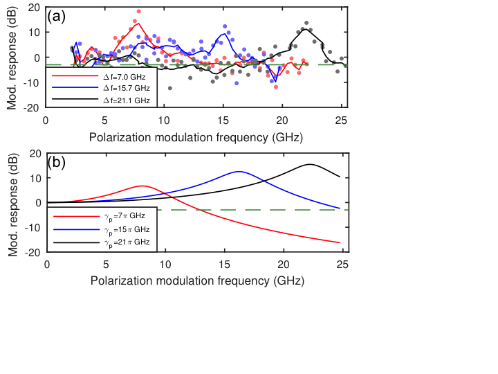
The corresponding experimental data in Fig. 17(a) which contain response resonance peaks at frequencies corresponding to the birefringence-induced mode splitting. This proves that the resonance frequency of the polarization modulation response can be tuned by the birefringence-induced mode splitting as well as the POs. The simulations in Fig. 17(b) using parameter set obtained in this work and methods from Section 5b resemble the resonance peaks from the experiment.
The advantages of highly-birefringent spin-VCSELs extend also to digital operation with abrupt changes between off and on injection (recall Section 3c). For IM,
| (29) |
where is the modulation amplitude and a binary function of the coded input signal, while analogous expression could be written for PM. The corresponding intensity or circular polarization of emitted light reflects information encoded into the input injection. For IM, bits ‘0’ and ‘1’ are defined by being above or below a specified threshold in the light intensity. For PM, ‘0’ and ‘1’ are encoded as left and right circular polarization.
To analyze the quality of digital data transfer, it is convenient to use eye diagrams, widely employed in conventional lasers Michalzik:2013 and introduced in spin-lasers Wasner2015:APL , where a binary signal, in Eq. (29), is simulated by 210 pseudorandom bits. An eye diagram is generated by dividing the laser wave form into segments of an equal bit size (two bits in Fig. 18) and overlaying them. A bit slot time (bit length) is an inverse of a bit rate. The central opening of an eye diagram resembles a human eye; a larger opening signifies a higher quality of a digital signal in terms of the reduced errors and noise. The width of an opening defines the time over which the received signal can be sampled error-free from intersymbol interference, while its height defines the noise margin.
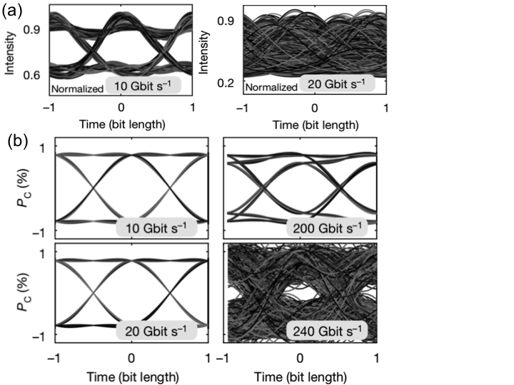
For the same set of VCSEL parameters and GHz, IM and PM are compared in Figs. 18(a) and (b). The closing eye diagram precludes data transfer by IM slightly above 10 Gbit s-1. In contrast, looking at the eye diagrams, we see that PM supports data transfer up to 240 Gbit s-1, showing a remarkable improvement in digital operation over conventional VCSELs, consistent with the increase of over from Fig. 16.
The principle of improving spin-lasers by an enhanced birefringence Gerhardt2011:APL ; FariaJunior2015:PRB ; Lindemann2019:N can be extended to other devices and wavelengths. Recent experimental results by Yokota and collaborators in InAlGaAs QW-based VCSELs Yokota2018:CLEO ; Yokota2018:APL verify that the PM bandwidth is enhanced by birefringence. With birefringence-induced splitting of 19 GHz the PM bandwidth reaches 23 GHz Yokota2018:CLEO . This demonstration is important as it is realized for 1.55 m emission, the optimal wavelength for long-haul communications, confirming the importance of tailoring polarization dynamics and spin imbalance in lasers.
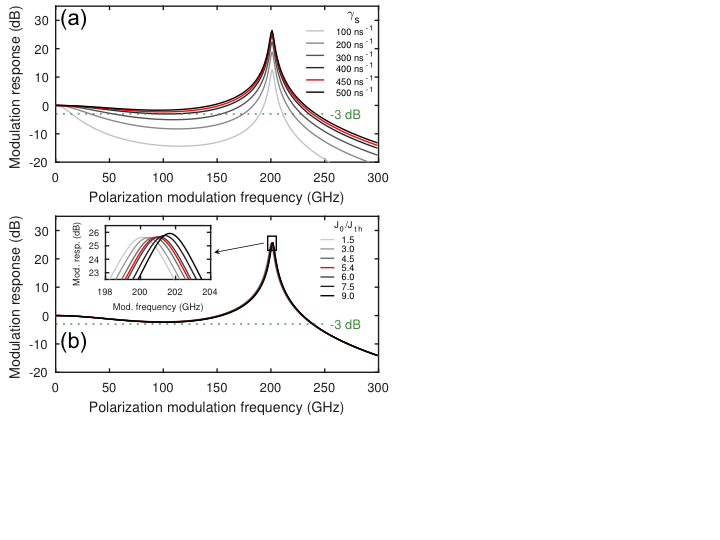
Unlike common approaches in spintronics and spin-lasers Zutic2004:RMP ; Iba2011:APL that seek to increase the spin relaxation time (), we find that short spin relaxation times are desirable for PM. With sufficiently fast spin relaxation, as long as is equal or larger than , Fig. 19(a) reveals that the modulation response at remains above dB, and therefore the PM bandwidth exceeds the . While in our VCSEL the spin-flip rate is close to its optimum value for a slightly above 200 GHz, this dependence of PM on confirms the importance of addressing multiple challenges for ultrafast spin-lasers, noted in Section 5a. Just high- values are not sufficient, even if they lead to high-frequency PO and it is also crucial to consider VCSEL design and other materials parameters for optimal performance. For future spin-VCSELs seeking to reach THz modulation bandwidth it is encouraging that high ns-1 was measured at 300 K for GaAs VCSELs Blansett2001:OE , allowing for GHz, while even higher is possible in (In,Ga)As devices Kini2008:JAP .
Another peculiar PM trend, as shown in Fig. 19(b), comes from the corresponding bandwidth dependence on the pumping power. The push for faster conventional VCSELs as well as other photonic devices typically requires a stronger pumping for IM, which leads to fundamental limitations. For example, simulating the device while neglecting heating effects, an increase in pumping from to enhances from 2.8 to 11.3 GHz and from 4.5 to 17.8 GHz. However, higher pumping generates higher dissipated power which increases the laser temperature. In contrast, for PM in Fig. 19(b) is almost independent of pumping. Thus, the highest bit rates can be already attained slightly above threshold. This has a great potential for ultra-low-power optical communication. In a conventional 850 nm VCSEL, a heat-to-data ratio fJ/bit at 25 Gbit/s was demonstrated Moser2012:EL . Utilizing PM for our devices, assuming pumping at with electrical spin-injection, a much lower fJ/bit could be obtained at a substantially higher bit rate of 240 Gbit/s.
.6 6. Conclusions and Outlook
While the study of spin-lasers is currently conducted by only a modest number of research groups, it offers fascinating opportunities building on advances in spintronics and conventional lasers. As in the research on their conventional counterparts, one can envision that spin-lasers could provide a versatile platform to study fundamental phenomena, from phase transitions to chaos Degiorgio1970:PRA ; Erneaux:2010 . These possibilities are now even richer by the control of spin degrees of freedom Raddo2017:SR . Furthermore, the instabilities found in lasers directly resemble instabilities in electronic devices Degiorgio1976:PT .
Since lasers provide highly-accurate and tunable parameters, important insights can be achieved by establishing mapping procedures between lasers and other cooperative phenomena, such as ferromagnetism Haken:1985 ; Degiorgio1970:PRA ; Degiorgio1976:PT . The concept of lasing is not limited to photons and there is a growing interest in the lasing of polaritons, quasiparticles resulting from the coupling between excitons and confined photons Deng2010:RMP . The control of microcavity polaritons is considered for exploring quantum phase transitions and realizing Bose-Einstein condensation in solids Deng2010:RMP ; Schneider2013:N . The demonstration of room-temperature spin-polariton lasers Bhattacharya2017:PRL , reveals novel opportunities to explore the implications of spin-polarized carriers and the helicity of light in lasers.
The potential of spin-lasers goes beyond fundamental phenomena, and there are many applications where they could offer important breakthroughs. A striking example is the growth in communication; from massive data centers, multicore microprocessors, and high-performance computing. The resulting limitations in communication and interconnects are the bottleneck in Moore’s law scaling and the main source of power dissipation Hecht2016:N ; Miller2017:JLT ; Miller2009:PIEEE ; Hilbert2011:S ; Jones2018:N . Impressive accomplishments in spin-lasers have already been realized. This pertains not only to demonstrating performance of lasers superior to their conventional counterparts, as discussed in Section 5, but also to elucidating novel concepts and operation principles in spintronics. Simultaneous spin polarization of electrons and holes, a coupling between spin, carrier, and photon dynamics, amplification, and strong nonlinear response, offer many unexplored opportunities. The modulation of spin polarization in lasers has motivated introducing the concept of spin interconnects Dery2011:APL ; Zutic2011:NM while using the spin-polarized carriers can also enable coherent emission of phonons Khaetskii2013:PRL .
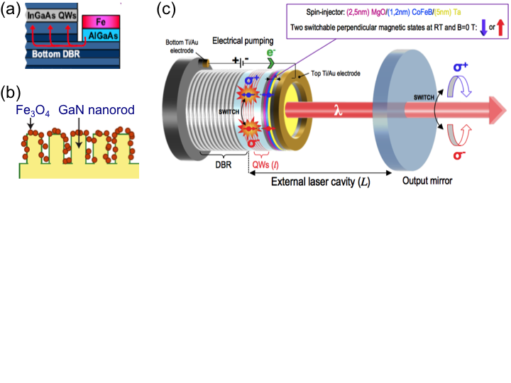
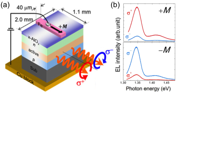
For practical applications it would be important to go beyond the commonly employed optically-pumped lasers and realize their room-temperature electrical operation. Some of the related challenges can be seen from an early demonstration of electrical spin injection in a spin VCSEL Holub2007:PRL , depicted in Fig. 20(a) and also in Fig. 3. With the distance of several m between the spin injector (Fe) and the gain region [(In,Ga)As QW], through spin relaxation the spin polarization of injected carriers is substantially reduced when it reaches the gain region Soldat2011:APL , limiting the electrical operation to 100 K Holub2007:PRL . Replacing the QW by QD gain region can enhance the operation temperature up to 230 K using MnAs injector Saha2010:PRB . A strong confinement in QDs can suppress the effect of spin-orbit coupling, a leading mechanism for the spin relaxation of carriers and thus enhance the spin relaxation time Zutic2004:RMP . While a long spin-relaxation time is needed for a material between the spin injector and the gain region, such that an appreciable spin polarization reaches the gain region, we see from Section 5 that in the gain region itself a short spin relaxation time could be desirable to enhance the modulation bandwidth for highly-birefringent lasers. Experimental room-temperature spin injection in MnAs-based spin-LEDs Fraser2010:APL is also encouraging for a room-temperature spin injection in lasers.
To implement a robust room-temperature electrical spin injection in lasers it will help to use the knowledge from spin injection in LEDs, as well as the suitable choice of materials and interface quality between the ferromagnets and semiconductors, which both determine the efficiency of spin injection Hanbicki2002:APL ; Hanbicki2003:APL ; Zega2005:PRL ; Salis2005:APL . Adopting advances in commercial devices based on MgO-barriers for large magnetoresistive effects will be useful Tsymbal:2019 . With the spatial separation between the spin injector and gain region, it is important to establish an accurate modeling of spin transport. Spintronic devices usually rely on magnetoresistive effects and unipolar transport; where only one type of carriers (electrons) plays an active role such that the equivalent resistor picture is usually sufficient to describe spin transport and spin injection.
In contrast, for modeling bipolar spintronic devices Zutic2006:IBM ; Zutic2007:JPCM , including spin-lasers, it is important to recognize limitations of the equivalent resistor picture Zutic2004:RMP . Deviations from local charge neutrality, band bending, nonlinear current-voltage characteristics, an explicit bias-dependence of spin injection and the presence of both electrons and holes are neglected in this approach. From the self-consistent description using generalized drift-diffusion and Poisson equations Zutic2001:PRB ; Zutic2006:PRL ; Zutic2002:PRL , one can see that in semiconductor junctions current-voltage nonlinearities are important even at small bias. The spin injection strongly depends on the applied bias Crooker2009:PRB ; Li2009:APL , not just on the relative resistances of the two regions.
While almost all spin-lasers have been based on zinc-blende semiconductors, such as GaAs or InAs, a spin-laser with a gain region made of a wurtzite semiconductor (GaN-based) has been the first case of an electrically manipulated spin-laser at room temperature Cheng2014:NN . Both the polarization and the intensity of the emitted light were tunable by external bias. That operation was realized through spin-filtering by integrating nanomagnets with the active region of an optically pumped nanorod laser as illustrated in Fig. 20(b). The nanomagnets were too small to support ferromagnetism and a modest applied field (0.35 T) was needed to magnetically align them. Unlike typical gain regions in which hole spin relaxation times is much shorter than for electrons, in GaN these times are comparable Brimont2009:APL , which modifies not only the used REs, but also the microscopic gain calculations since holes are also spin polarizaed FariaJunior2017:PRB . Such considerations are also relevant for bulk GaN-based spin-polariton lasers, where the spin polarization of holes was neglected Bhattacharya2017:PRL . There, with the edge emission, an in-plane magnetization of FeCo/MgO spin injector requires no magnetic field for room-temperature operation.
An alternative path to electrical operation of spin-lasers at room temperature is sought with external-cavity lasers (VECSELs, noted in Section 1) Frougier2015:OE , shown in Fig. 20(c). They could enable depositing a thin-film ferromagnet just 100-200 nm away from the active region, sufficiently close to attain a considerable spin polarization of carriers in the gain region at room temperature. With complementary properties to better-studied spin-VCSELs, such spin-VECSELs could offer higher power and reduced noise. Recent progress in modeling VECSELs using a vectorial model Alouini2018:OE could provide important guidance how the design of optical anisotropies enables an improved polarization dynamics, reflecting their behavior as overdamped harmonic oscillators.
For both VECSEL and VCSEL geometries it is desirable to implement a spin injector with perpendicular anisotropy allowing operation in remanence Sinsarp2007:JJAP ; Hovel2008:APLa ; Zarpellon2012:PRB . An independent progress in spintronics to store and sense information using magnets with a perpendicular anisotropy Tsymbal:2019 could then also be directly beneficial for spin-lasers. Electrical spin injection usually relies on magnetic thin films with in-plane anisotropy requiring a large applied magnetic field to achieve an out-of-plane magnetization and the projection of injected spin compatible with the carrier recombination of circularly polarized light in surface-emitting lasers.
For spin modulation of lasers a steady-state electrical spin injection alone may not be enough and it is useful to recognize related advances in spintronics pertaining to magnetization dynamics, and variety of phenomena: from spin-transfer and spin-orbit torques, to spin pumping Tsymbal:2019 . The progress in fast magnetization reversal Garzon2008:PRB ; Kimel2005:N ; Kirilyuk:2019 and spin-LEDs showing electrical helicity switching Nishizawa2014:APL ; Nishizawa2017:PNAS ; Nishizawa2018:APE ; Munekata2020:P , see Fig. 21, could stimulate all-electrical schemes for spin modulation in lasers, to realize enhanced bandwidth discussed in Sections 3 and 5. Remarkably, unlike the expected maximum of 50 % circular polarization Zutic2004:RMP for a bulk III-V semiconductor used in Fig. 21, such a spin-LED demonstrates room-temperature % in remanence! Such helicity control is promising for secure communications and biomedical applications Nishizawa2017:PNAS ; Nishizawa2020:JJAP To understand this behavior and using it in electrically-operated spin-lasers, it is important to develop more general models of spin-transport and accurate gain calculations, which would benefit from recent advances in methods To2019:T .
Another direction to realize novel spin-lasers could build on a huge interest in two-dimensional materials and van der Waals heterostructures which are suitable for low-power spintronic applications Lin2019:NE . Following our suggestion for atomically-thin spin-lasers based on a gain region made of transition metal dichalcogenides Lee2014:APL ; Lindemann2019:N , we anticipate that their room-temperature electrical operation could be realized through magnetic proximity effects Zutic2019:MT . A leaking magnetism from a nearby magnet would create proximity-induced spin-splitting Zutic2019:MT ; Zhao2017:NN ; Zhong2017:SA that could be changed by electric gating or altering the direction of magnetization Lazic2016:PRB ; Xu2018:NC . Moreover, magnetic proximity effects in transition metal dichalcogenides could transform the optical selection rules and tightly-bound electron-hole pairs Scharf20017:PRL , providing an intriguing opportunity for tunable spin-lasers.
Acknowledgments
This work has been supported by the NSF ECCS-1810266, US ONR N000141712793, German Research Foundation, grants No. 250699912 and 392782903, and SFB 1277, FAPESP grants No. 2012/05618-0 and 2013/23393-8, Alexander von Humboldt Foundation, Capes grants No. 99999.000420/2016-06 and 88881.068174/2014-01, CNPq grants No. 408916/2018-4 and 308806/2018-2. We thank S. Bearden, G. Boeris, D. Cao, Y.-F. Chen, H. Dery, C. Gøthgen, N. Jung, R. Michalzik, T. Pusch, and E. Wasner for valuable discussions.
References
- (1) S. L. Chuang, Physics of Optoelectronic Devices, 2nd ed. (Wiley, New York, 2009).
- (2) L. A. Coldren, S. W. Corzine, and M. L. Mašović, Diode Lasers and Photonic Integrated Circuits, 2 Edition (Wiley, Hoboken, 2012).
- (3) A. Yariv, Optical Electronics in Modern Communications, 5th Edition (Oxford Univ. Press, New Yok, 1997).
- (4) VCSELs Fundamentals, Technology and Applications of Vertical-Cavity Surface-Emitting Lasers, edited by R. Michalzik (Springer, Berlin, 2013).
- (5) J. Hecht, The bandwidth bottleneck, Nature 536, 139 (2016).
- (6) D. A. B. Miller, Attojoule Optoelectronics for Low-Energy Information Processing and Communications - a Tutorial Review, J. Lightwave Tech. 3, 346 (2017).
- (7) D. A. B. Miller, Device Requirements for Optical Interconnects to Silicon Chips, Proc. IEEE 97, 1166 (2009).
- (8) M. Hilbert and P. López, The world’s technological capacity to store, communicate, and compute information, Science 332, 60 (2011).
- (9) N. Jones, The information factories, Nature 561, 163 (2018).
- (10) J. Lee, S. Bearden, E. Wasner, and I. Žutić, Spin-lasers: From threshold reduction to large-signal analysis, Appl. Phys. Lett. 105, 042411 (2014).
- (11) H. Haken, Light, Vol. 2 Laser Light Dynamics (North-Holland, New York, 1985).
- (12) V. Degiorgio and. M. O. Scully, Analogy between the laser threshold region and a second-order phase transition, Phys. Rev. A 2, 1170 (1970).
- (13) V. Degiorgio, The laser instability, Phys. Today 29, 42 (1976).
- (14) J. Lee, R. Oszwaldowski, C. Gothgen, and I. Žutić, Mapping between quantum dot and quantum well lasers: From conventional to spin lasers, Phys. Rev. B 85, 045314 (2012).
- (15) M. A. Parker, Physics of Optoelectronics (CRC Press, New York, 2005).
- (16) Optical Orientation, edited by F. Meier and B. P. Zakharchenya (North-Holland, New York, 1984).
- (17) I. Žutić, J. Fabian and S. Das Sarma, Spintronics: Fundamantals and applications, Rev. Mod. Phys. 76, 323 (2004).
- (18) H. Soldat, M. Y. Li, N. C. Gerhardt, M. R. Hofmann, A. Ludwig, A. Ebbing, D. Reuter, A. D. Wieck, F. Stromberg, W. Keune, and H. Wende, Room temperature spin relaxation length in spin light-emitting diodes, Appl. Phys. Lett. 99, 051102 (2011).
- (19) J. Frougier, G. Baili, I. Sagnes, D. Dolfi, J.-M. George, and M. Alouini, Accurate measurement of the residual birefringence in VECSEL: Towards understanding of the polarization behavior under spin-polarized pumping, Opt. Expr. 23, 9573 (2015).
- (20) J. Sinova and I. Žutić, The new moves of the spintronics tango, Nat. Mater. 11, 368 (2012).
- (21) S. Hallstein, J. D. Berger, M. Hilpert, H. C. Schneider, W. W. Rühle, F. Jahnke, S. W. Koch, H. M. Gibbs, G. Khitrova, M. Oestreich, Manifestation of coherent spin precession in stimulated semiconductor emission dynamics, Phys. Rev. B 56, R7076 (1997).
- (22) H. Ando, T. Sogawa, and H. Gotoh, Photon-spin controlled lasing oscillations in surface-emitting lasers, Appl. Phys. Lett. 73, 566 (1998).
- (23) J. Rudolph, D. Hägele, H. M. Gibbs, G. Khitrova, and M. Oestreich, Laser threshold reduction in a spintronic device, Appl. Phys. Lett. 82, 4516 (2003).
- (24) J. Rudolph, S. Döhrmann, D. Hägele, M. Oestreich, and W. Stolz, Room-temperature threshold reduction in vertical-cavity surface-emitting lasers by injection of spin-polarized carriers, Appl. Phys. Lett. 87, 241117 (2005).
- (25) N. C. Gerhardt, S. Hövel, M. R. Hofmann, J. Yang, D. Reuter, A. Wieck, Enhancement of spin information with vertical cavity surface emitting lasers, Electron. Lett. 42, 88 (2006).
- (26) M. Holub, J. Shin, and P. Bhattacharya, Electrical spin injection and threshold reduction in a semiconductor laser, Phys. Rev. Lett. 98, 146603 (2007).
- (27) S. Hövel, A. Bischoff, N. C. Gerhardt, M. R. Hofmann, T. Ackemann, A. Kroner, and R. Michalzik, Optical spin manipulation of electrically pumped vertical-cavity surface-emitting lasers, Appl. Phys. Lett. 92, 041118 (2008).
- (28) D. Basu, D. Saha, C. C. Wu, M. Holub, Z. Mi, and P. Bhattacharya, Electricallly injected InAs/GaAs quantum dot spin laser operating at 200 K, Appl. Phys. Lett. 92, 091119 (2008).
- (29) D. Basu, D. Saha, and P. Bhattacharya, Optical polarization modulation and gain anisotropy in an electrically injected spin laser, Phys. Rev. Lett. 102, 093904 (2009).
- (30) H. Fujino, S. Koh, S. Iba, T. Fujimoto, and H. Kawaguchi, Circularly polarized lasing in a (110)-oriented quantum well vertical-cavity surface-emitting laser under optical spin injection, Appl. Phys. Lett. 94, 131108 (2009).
- (31) K. Ikeda, T. Fujimoto, H. Fujino, T. Katayama, S. Koh, and H. Kawaguchi, Switching of lasing circular polarizations in (110)-VCSEL, IEEE Phot. Tech. Lett. 21, 1350 (2009).
- (32) D. Saha, D. Basu, and P. Bhattacharya, High-frequency dynamics of spin-polarized carriers and photons in a laser, Phys. Rev. B 82, 205309 (2010).
- (33) M. Y. Li, H. Jähme, H. Soldat, N. C. Gerhardt, M. R. Hofmann, T. Ackemann, A. Kroner, and R. Michalzik, Birefringence controlled room-temperature picosecond spin dynamics close to the threshold of vertical-cavity surface-emitting laser devices, Appl. Phys. Lett. 97, 191114 (2010).
- (34) N. C. Gerhardt, M. Y. Li, H. Jähme, H. Höpfner, T. Ackemann, and M. R. Hofmann, Ultrafast spin-induced polarization oscillations with tunable lifetime in vertical-cavity surface-emitting lasers, Appl. Phys. Lett. 99, 151107 (2011).
- (35) S. Iba, S. Koh, K. Ikeda, and H. Kawaguchi, Room temperature circularly polarized lasing in an optically spin injected vertical-cavity surface-emitting laser with (110) GaAs quantum wells, Appl. Phys. Lett. 98, 081113 (2011).
- (36) J. Frougier, G. Baili, M. Alouini, I. Sagnes, H. Jaffrès, A. Garnache, C. Deranlot, D. Dolfi, and J.-M. George, Appl. Phys. Lett. 103, 252402 (2013).
- (37) H. Höpfner, M. Lindemann, N. C. Gerhardt, and M. R. Hofmann, Controlled switching of ultrafast circular polarization oscillations in spin-polarized vertical-cavity surface-emitting lasers, Appl. Phys. Lett. 104, 022409 (2014).
- (38) J.-Y. Cheng, T.-M. Wond, C.-W. Chang, C.-Y. Dong, and Y.-F Chen, Self-polarized spin-nanolasers, Nat. Nanotechnol. 9, 845 (2014).
- (39) S. S. Alharthi, A. Hurtado, V.-M. Korpijarvi, M. Guina, I. D. Henning, and M. J. Adams, Circular polarization switching and bistability in an optically injected 1300 nm spin-vertical cavity surface emitting laser, Appl. Phys. Lett. 106, 021117 (2015).
- (40) F.-k. Hsu, W. Xie, Y.-S. Lee, S.-D. Lin, and C.-W. Lai, Spin-polarized lasing in a highly photoexcited semiconductor microcavity, Phys. Rev. B 91, 195312 (2015).
- (41) A. Bhattacharya, M. Zunaid Baten, I. Iorsh, T. Frost, A. Kavokin, and P. Bhattacharya, Room-temperature spin polariton diode laser, Phys. Rev. Lett. 119, 067701 (2017).
- (42) J. Fabian, A. Mathos-Abiague, C. Ertler, P. Stano, and I. Žutić, Semiconductor spintronics, Acta Phys. Slov. 57, 565 (2007).
- (43) S. Maekawa, and T. Shinjo, eds., Spin Dependent Transport in Magnetic Nanostructures (Taylor & Francis, New York, 2002).
- (44) S. S. P. Parkin, C. Kaiser, A. Panchula, P. M. Rice, B. Hughes, M. Samant, and S.-H. Yang, Room temperature tunneling magnetoresistance in magnetic tunnel junctions with MgO(100) tunnel barriers, Nat. Mater. 3, 862 (2004).
- (45) S. Yuasa, T. Nagahama, A. Fukushira, Y. Suzuki, and K. Ando, Giant room-temperature magnetoresistance in single-crystal Fe/MgO/Fe magnetic tunnel junctions, Nat. Mater. 3, 868 (2004).
- (46) Spintronics Handbook Spin Transport and Magnetism, edited by E. Y. Tsymbal and I. Žutić 2nd Edition, (Taylor & Francis/CRC Press, Boca Raton, FL 2019).
- (47) S. Das Sarma, J. Fabian, X. D. Hu, and I. Žutić, Spintronics: Electron spin coherence, entanglement, and transport, Superlattices Microstruct. 27, 289 (2000).
- (48) S. Das Sarma, J. Fabian, X. D. Hu, and I. Žutić, Spin electronics and spin computation, Solid State Commun. 119, 207 (2001).
- (49) M. Lindemann, G. Xu, T. Pusch, R. Michalzik, M. R. Hofmann, I. Žutić, and N. C. Gerhardt, Ultrafast spin-Lasers, Nature 568, 212 (2019).
- (50) C. Gøthgen, R. Oszwałdowski, A. Petrou, and I. Žutić, Analytical model of spin-polarized semiconductor lasers, Appl. Phys. Lett. 93, 042513 (2008).
- (51) C. Gøthgen, Steady-state analysis of semiconductor spin-lasers, Ph. D. Thesis, University at Buffalo, 2010.
- (52) H.-H. Lee and W. Casperson, Gain and saturation in semiconductor lasers, Opt. Quant. Electron. 25, 369 (1993).
- (53) D. J. Hilton and C. L. Tang, Optical orientation and femtosecond relaxation of spin-polarized holes in GaAs, Phys. Rev. Lett. 89, 146601 (2002).
- (54) S. Fang, R. Zhu, and T. Lai, Spin relaxation dynamics of holes in intrinsic GaAs quantum wells studied by transient circular dichromatic absorption spectroscopy at room temperature, Sci. Rep. 7, 287 (2017).
- (55) M. Oestreich, J. Rudolph, R. Winkler, and D. Hägele, Design considerations for semiconductor spin lasers, Superlattices Microstruct. 37, 306 (2005).
- (56) G. Xu, J.Cao, V. Labinac, and I. Žutić, Intensity equations for birefringent spin-lasers, preprint.
- (57) M. Alouini, J. Frougier, A. Joly, G. Baïli, D. Dolfi, and J.-M. Georges, VSPIN: A new model relying on the vectorial description of the laser field for predicting the polarization dynamics of spin-injected V(e)CSELs, Opt. Express 26, 6739 (2018).
- (58) J. Faist, Quantum Cascade Lasers (Oxford Univ. Press, Oxford, 2013).
- (59) J. Lee, W. Falls, R. Oszwałdowski, and I. Žutić, Spin modulation in lasers, Appl. Phys. Lett. 97, 041116 (2010).
- (60) This is not essential but simplifies our analytical results.
- (61) D. Banerjee, R. Adari, M. Murthy, P. Suggisetti, S. Ganguly, and D. Saha, Modulation bandwidth of a spin laser, J. Appl. Phys. 109, 07C317 (2011).
- (62) G. Boeris, J. Lee, K. Vyborny, and I. Žutić, Tailoring chirp in spin-lasers, Appl. Phys. Lett. 100, 121111 (2012).
- (63) K. Petermann Laser Diode Modulation and Noise, (Kluwer Academic, Dordrecht, 1988).
- (64) P. E. Faria Junior, G. Xu,Y.-F. Chen, G. M. Sipahi, and I. Žutić, Wurtzite spin lasers, Phys. Rev. B 95, 115301 (2017).
- (65) K. F. Mak, K. He, J. Shan, and T. F. Heinz, Control of valley polarization in monolayer MoS2 by optical helicity, Nat. Nanotechnol. 7, 494 (2012).
- (66) R Oszwałdowski C. Gøthgen, and I. Žutić, Theory of quantum dot spin lasers, Phys. Rev. B 82, 085316 (2010).
- (67) P. E. Faria Junior, G. Xu, J. Lee, N. C. Gerhardt, G. M. Sipahi, and I. Žutić, Towards high-frequency operation of spin-lasers, Phys. Rev. B 92, 075311 (2015).
- (68) P. Yu and M. Cardona, Fundamentals of Semiconductors, 2nd Edition (Springer, New York, 2010).
- (69) M. Holub and B. T. Jonker, Threshold current reduction in spin-polarized lasers: Role of strain and valence-band mixing, Phys. Rev. B 83, 125309 (2011).
- (70) H. Haug and S. W. Koch, Quantum Theory of Optical and Electronic Properties of Semiconductors, 4 Edition (World Scientific Publishing, Singapore 2004).
- (71) W. W. Chow and S. W. Koch, Semiconductor-Laser Fundamentals: Physics of the Gain Materials (Springer, New York, 1999).
- (72) P. E. Faria Junior, Development and application of the method to investigate spin and optical properties of semiconductor nanostructures, Ph.D. Thesis. Instituto de Física de São Carlos, Universidade de São Paulo, Brazil, 2016.
- (73) M. P. van Exter, A. K. Jansen van Doorn, and J. P. Woerdman, Electro-optic effect and birefringence in semiconductor vertical-cavity lasers, Phys. Rev. A 56, 845 (1997).
- (74) M. Sondermann, M. Weinkath, and T. Ackemann, Polarization switching to the gain disfavored mode in vertical-cavity surface-emitting lasers, IEEE J. Quantum Electron. 40, 97 (2004).
- (75) M. Virte, K. Panajotov, H. Thienpont, and M. Sciamanna, Deterministic polarization chaos from a laser diode, Nat. Photonics 7, 60 (2012).
- (76) R. Al-Seyab, D. Alexandropoulos, I. D. Henning, and M. J. Adams, Instabilities in spin-polarized vertical-cavity surface-emitting lasers, IEEE Photon. J. 3, 799 (2011).
- (77) M. San Miguel, Q. Feng, and J. V. Moloney, Light-polarization dynamics in surface-emitting semiconductor lasers, Phys. Rev. A 52, 1728 (1995).
- (78) N. Yokota, R. Takeuchi, H. Yasaka, and K. Ikeda, Lasing polarization characteristics in 1.55-m spin-injected VCSELs, IEEE Photon. Tech. Lett. 29, 711 (2017).
- (79) T. Fordos, H. Jaffres, K. Postava, M. S. Seghilani, A. Garnache, J. Pistora, and H. J. Drouhin, Eigenmodes of spin vertical-cavity surface-emitting lasers with local linear birefringence and gain dichroism, Phys. Rev. A 96, 043828 (2017).
- (80) N. C. Gerhardt and M. R. Hofmann, Spin-controlled vertical-cavity surface-emitting lasers, Adv. Opt. Techn. 2012, 268949 (2012).
- (81) J. Mulet and S. Balle, Spatio-temporal modeling of the optical properties of VCSELs in the presence of polarization effects, IEEE J. Quantum Electron. 38, 291 (2002).
- (82) D. Burak, J. V. Moloney, and R. Binder, Microscopic theory of polarization properties of optically anisotropic vertical-cavity surface-emitting lasers, Phys. Rev. A 61, 053809 (2000).
- (83) Burak, J. V. Moloney, and R. Binder, Macroscopic versus microscopic description of polarization properties of optically anisotropic vertical-cavity surface-emitting lasers, IEEE J. Quant. Electron. 36, 956 (2000).
- (84) N. Haghighi, G. Larisch, R. Rosales, M. Zorn, and J. A. Lott, 35 GHz bandwidth with directly current modulated 980 nm oxide aperture single cavity VCSELs, 2018 IEEE Int. Semiconductor Laser Conf. (ISLC) https://doi.org/10.1109/ISLC.2018.8516258 (2018).
- (85) M. Lindemann, T. Pusch, R. Michalzik, N. C Gerhardt, and M. R. Hofmann, Frequency tuning of polarization oscillations: Toward high-speed spin-lasers, Appl. Phys. Lett. 108, 042404 (2016).
- (86) K. Panajotov, B. Nagler, G. Verschaffelt, A. Georgievski, H. Thienpont, J. Danckaert, and I. Veretennicoff, Impact of in-plane anisotropic strain on the polarization behavior of vertical-cavity surface-emitting lasers, Appl. Phys. Lett. 77, 1590 (2000).
- (87) T. Pusch, E. La Tona, M. Lindemann, N. C. Gerhardt, M. R. Hofmann, and R. Michalzik, Monolithic vertical-cavity surface-emitting laser with thermally tunable birefringence, Appl. Phys. Lett. 110, 151106 (2017).
- (88) T. Pusch, P. Debernardi, M. Lindemann, F. Erb, N. C. Gerhardt, M. R. Hofmann, and R. Michalzik, Vertical-cavity surface-emitting laser with integrated surface grating for high birefringence splitting Electron. Lett. 55, 1055 (2019).
- (89) T. Pusch, M. Lindemann, N. C. Gerhardt, M. R. Hofmann, and R. Michalzik, Vertical-cavity surface-emitting lasers with birefringence above 250 GHz, Electron. Lett. 51, 1600 (2015).
- (90) O. Hess and T. Kuhn, Maxwell-Bloch equations for spatially inhomogeneous semiconductor lasers. I. Theoretical formulation, Phys. Rev. A 54, 3347 (1996).
- (91) C. M. Bowden and G. P. Agrawal, Generalized Bloch-Maxwell formulation for semiconductor lasers, Opt. Commun.100, 147 (1993).
- (92) E. Wasner, S. Bearden, J. Lee, and I. Žutić, Digital operation and eye diagrams in spin-lasers, Appl. Phys. Lett. 107, 082406 (2015).
- (93) N. Yokota, K. Nisaka, H.Yasaka, and K. Ikeda, High-speed modulation of 1.55-m VCSELs with spin polarization modulation, Conf. Lasers and Electro-Optics https://doi.org/10.1364/CLEO_SI.2018.STu3Q.2 (Optical Society of America, 2018).
- (94) N. Yokota, K. Nisaka, H.Yasaka, and K. Ikeda, Spin polarization modulation for high-speed vertical-cavity surface-emitting lasers, Appl. Phys. Lett. 113, 171102 (2018).
- (95) E. L. Blansett, M. G. Raymer, G. Khitrova, H. M. Gibbs, D. K. Serkland, A. A. Allerman, and K. M. Geib, Ultrafast polarization dynamics and noise in pulsed vertical-cavity surface-emitting lasers, Opt. Express 9, 312 (2001).
- (96) R. N. Kini, K. Nontapot, G. A. Khodaparast, R. E. Welser, and L. J. Guido, Time resolved measurements of spin and carrier dynamics, J. Appl. Phys. 103, 064318 (2008).
- (97) P. Moser, J. A. Lott, P. Wolf, G. Larisch, H. Li, N. N. Ledentsov, and D. Bimberg, 56 fJ dissipated energy per bit of oxide-confined 850 nm VCSELs operating at 25 Gbit/s, Electron. Lett. 48, 1292 (2012).
- (98) T. Erneux and P. Glorieux, Laser Dynamics (Cambridge University Press, Cambridge, 2010).
- (99) T. R. Raddo, K. Panajotov, B.-H. Borges, and M. Virte, Strain induced polarization chaos in a solitary VCSEL, Sci. Rep. 7, 14032 (2017).
- (100) H. Dery, Y. Song, P. Li, and I. Žutić, Silicon spin communication, Appl. Phys. Lett. 99, 082502 (2011).
- (101) I. Žutić and H. Dery, Taming spin currents, Nat. Mater. 10, 647-648 (2011).
- (102) A. Khaetskii, V. N. Golovach, X.Hu, and I. Žutić, Proposal for a phonon laser utilizing quantum-dot spin states, Phys. Rev. Lett. 111, 186601 (2013).
- (103) H. Deng, H. Haug, and Y. Yamamoto, Exciton-polariton Bose-Einstein condensation, Rev. Mod. Phys. 82, 1489 (2010).
- (104) C. Schneider, A. Rahimi-Iman, N. Y. Kim, J. Fischer, I. G. Savenko, M. Amthor, M. Lermer, A. Wolf, L. Worschech, V. D. Kulakovskii, I. A. Shelykh, M. Kamp, S. Reitzenstein, A. Forchel, Y. Yamamoto, and S. Höfling, An electrically pumped polariton laser, Nature 497, 348 (2013).
- (105) E. D. Fraser, S. Hegde, L. Schweidenback, A. H. Russ, A. Petrou, H. Luo, and G. Kioseoglou, Efficient electron spin injection in MnAs-based spin-light-emitting-diodes up to room temperature, Appl. Phys. Lett. 97, 041103 (2010).
- (106) A. T. Hanbicki, B. T. Jonker, G. Itskos, G. Kioseoglou, and A. Petrou, Detection of spin-polarized electrons injected into two-dimensional electron gas, Appl. Phys. Lett. 81, 2131(2002).
- (107) A. T. Hanbicki, O. M. van’t Erve, R. Magno, G. Kioseoglou, C. H. Li, B. T. Jonker, G. Itskos, R. Mallory, and A. Petrou, Analysis of the transport process providing spin injection through an Fe/AlGaAs Schottky barrier, Appl. Phys. Lett. 82, 4092 (2003).
- (108) T. J. Zega, A. T. Hanbicki, S. C. Erwin, I. Žutić, G. Kioseoglou, C. H. Li, B. T. Jonker, and R. M. Stroud, Determination of interface atomic structure and its impact on spin transport using Z-contrast microscopy and density-functional theory, Phys. Rev. Lett. 96, 196101 (2006).
- (109) G. Salis, R. Wang, X. Jiang, R. M. Shelby, S. S. P. Parkin, S. R. Bank, and J. S. Harris, Temperature independence of the spin-injection efficiency of a MgO-based tunnel spin injector, Appl. Phys. Lett. 87, 262503 (2005).
- (110) I. Žutić, J. Fabian, and S. C. Erwin, Bipolar spintronics: Fundamentals and applications, IBM J. Res. & Dev. 50, 121 (2006).
- (111) I. Žutić, J. Fabian, and S. C. Erwin, Bipolar spintronics: From spin injection to spin-controlled logic, J. Phys.: Condens. Matter 19, 165219 (2007).
- (112) I. Žutić, J. Fabian, and S. Das Sarma, Spin injection through the depletion layer: a theory of spin-polarized p-n junctions and solar cells, Phys. Rev. B 64, 121201(R) (2001).
- (113) I. Žutić, J. Fabian, and S. C. Erwin, Spin injection and detection in silicon, Phys. Rev. Lett. 97, 026602 (2006).
- (114) I. Žutić and J. Fabian and S. Das Sarma, Spin-polarized transport in inhomogeneous magnetic semiconductors: Theory of magnetic/nonmagnetic p-n junctions, Phys. Rev. Lett. 88, 066603 (2002).
- (115) P. Li and H. Dery, Tunable spin junction, Appl. Phys. Lett. 94, 192108 (2009).
- (116) S. A. Crooker, E. S. Garlid, A. N. Chantis, D. L. Smith, K. S. M. Redd, Q. O. Hu, T. Kondo, and C. J. Palmstrøm, and P. A. Crowell, Bias-controlled sensitivity of ferromagnet/semiconductor electrical spin detectors, Phys. Rev. B 80, 041305 (2009).
- (117) C. Brimont, M. Gallart, A. Gadalla, O. Crégut, B. Hönerlage, and P. Gilliot, Dislocation density and band structure effects on spin dynamics in GaN, J. Appl. Phys. 105, 023502 (2009).
- (118) A. Sinsarp, T. Manago, F. Takano, and H. Akinaga, Electrical spin injection from out-of-plane magnetized FePt/MgO tunneling junction into GaAs at room temperature, Jpn. J. Appl. Phys. 46, L4 (2007).
- (119) S. Hövel, N.C. Gerhardt, M.R. Hofmann, F.-Y. Lo, A. Ludwig, D. Reuter, A.D. Wieck, E. Schuster, H. Wende, W. Keune, O. Petracic, and K. Westerholt, Room temperature electrical spin injection in remanence, Appl. Phys. Lett. 93, 021117 (2008).
- (120) J. Zarpellon, H. Jaffres, J. Frougier, C. Deranlot, J. M. George, D. H. Mosca, A. Lemaitre, F. Freimuth, Q. H. Duong, P. Renucci, and X. Marie, Spin injection at remanence into III-V spin light-emitting diodes using (Co/Pt) ferromagnetic injectors, Phys. Rev. B 86, 205314 (2012).
- (121) S. Garzon, L. Ye, R. A. Webb, T. M. Crawford, M. Covington, and S. Kaka, Coherent control of nanomagnet via ultrafast spin torque pulses, Phys. Rev. B 78, 180401(R) (2008).
- (122) A. V. Kimel, A. Kirilyuk, P. A. Usachev, R. V. Pisarev, A. M. Balbashov, and Th. Rasing, Ultrafast non-thermal control of magnetization by instantaneous photomagnetic pulses, Nature 435, 655 (2005).
- (123) A. Kirilyuk, A. V. Kimel, and Th. Rasing, All-optical switching of magnetization: From fundamentals to nanoscale recording, in Spintronics Handbook Spin Transport and Magnetism, edited by E. Y. Tsymbal and I. Žutić 2nd Edition, (Taylor & Francis/CRC Press, Boca Raton, FL 2019).
- (124) N. Nishizawa, K. Nishibayashi, and H. Munekata, A spin light emitting diode incorporating ability of electrical helicity switching, Appl. Phys. Lett. 104, 111102 (2014).
- (125) N. Nishizawa, K. Nishibayashi, and H. Munekata, Pure circular polarization electroluminescence at room temperature with spin-polarized light-emitting diodes, Proc. Nat. Acad. Sci. 114, 1783 (2017).
- (126) N. Nishizawa, M. Aoyama, R. C. Roca, K. Nishibayashi, and H. Munekata, Arbitrary helicity control of circularly polarized light from lateral-type spin-polarized light-emitting diodes at room temperature, Apl. Phys. Express 11, 053003 (2018).
- (127) H. Munekata, Low-threshold pure-circular polarization electro-luminescence from spin-light-emitting diodes consisting of oxidized Al/AlAs tunnel barriers, preprint (2020).
- (128) N. Nishizawa, A. Hamada, K. Takahashi, T. Kuchimaru, and H. Munekata, Monte Carlo simulation of scattered circularly polarized light in biological tissues for detection technique of abnormal tissues using spin-polarized light emitting diodes, Jap. J. Appl. Phys. 59, SEEG03 (2020).
- (129) D.-Q. To, Advanced multiband methods for semiconductor-based spinorbitronics, Ph.D. Thesis. Ecole Polytechique, Universite Paris-Saclay France, 2019.
- (130) X. Lin, W. Yang, K. L. Wang, and W. Zhao, Two-dimensional spintronics for low-power electronics, Nat. Electron. 2, 374 (2019).
- (131) I. Žutić, A. Matos-Abiague, B. Scharf, H. Dery, and K. Belashchenko, Proximitized materials, Mater. Today 22, 85 (2019).
- (132) C. Zhao, T. Norden, P. Zhao, Y. Cheng, P. Zhang, F. Sun, P. Taheri, J. Wang, Y. Yang, T. Scrace, K. Kang, S. Yang, G. Miao, R. Sabirianov, G. Kioseoglou, A. Petrou, and H. Zeng, Enhanced valley splitting in monolayer WSe2 due to magnetic exchange field, Nat. Nanotechnol. 12, 757–763 (2017).
- (133) D. Zhong, K. L. Seyler, X. Linpeng, R. Cheng, N. Sivadas, B. Huang, E. Schmidgall, T. Taniguchi, K. Watanabe, M. A. McGuire, W. Yao, D. Xiao, K.-M. C. Fu, and X. Xu, van der Waals engineering of ferromagnetic semiconductor heterostructures for spin and valleytronics, Sci. Adv. 3, e1603113 (2017).
- (134) P. Lazić, K. D. Belashchenko, and I. Žutić, Effective gating and tunable magnetic proximity effects in two-dimensional heterostructures, Phys. Rev. B 93, 241401(R) (2016).
- (135) J. Xu, S. Singh, J. Katoch, G. Wu, T. Zhu, I. Žutić, and R. K. Kawakami, Spin inversion in graphene spin valves by gate-tunable magnetic proximity effect at one-dimensional contacts, Nat. Commun. 9, 2869 (2018).
- (136) B. Scharf, G. Xu, A. Matos-Abiague, and I. Žutić, Magnetic proximity effects in transition-metal dichalcogenides: Converting excitons, Phys. Rev. Lett. 119, 127403 (2017).