MITIGATION OF COLLECTIVE EFFECTS BY OPTICS OPTIMISATION
Abstract
This paper covers recent progress in the design of optics solutions to minimize collective effects such as beam instabilities, intra-beam scattering or space charge in hadron and lepton rings. The necessary steps are reviewed for designing the optics of high-intensity and high-brightness synchrotrons but also ultra-low emittance lepton storage rings, whose performance is strongly dominated by collective effects. Particular emphasis is given to proposed and existing designs illustrated by simulations and beam measurements.
1 INTRODUCTION
The physics quantities parametrising the performance of a large variety of hadron and lepton rings, as, for example, the average beam power of synchrotron based proton drivers, the luminosity of colliders, the brightness of their associated injectors or the brilliance of X-ray storage rings, are proportional to the beam intensity or to its ratio with the beam dimensions. The modern tendency is to push the performance frontiers towards extreme conditions, i.e. the highest beam intensity contained within ultra-low beam volumes, under which the collective behaviour of the beam becomes predominant. It is thus of paramount importance to take measures in order to alleviate collective effects in the early phase of the design, which usually begins with the optimisation of the linear optics.
This is by far not an easy task, as already there is a large amount of optics conditions based on single-particle constraints to be satisfied, including non-linear dynamics. Thereby, the parameter space becomes entangled and difficult to control and optimise. One should rely on analytical and numerical methods for obtaining a global parameterisation, including collective effects.
In the case of rings in operation, dealing with collective effects usually implicates mitigation techniques based on the use of multi-pole magnets [1] or higher harmonic RF cavities [2] for providing Landau damping, dedicated feedback systems [3] or the reduction of the beam interaction with its environment through careful vacuum and low-impedance component design [4]. Changing the linear optics, without major upgrade involving radical modifications of the machine configuration, is an unconventional approach, since it is subject to the constraints of the existing magnet and powering systems. It can be even more challenging because of its interplay with the already optimised operation of critical systems, such as beam transfer elements or RF. On the other hand, if a viable solution is found, it can be a very cost effective way to overcome existing intensity or brightness limits. In addition, it may be used to relax tolerances associated with the above-mentioned mitigation measures for reducing collective effects.
This paper is organised as follows: after describing the basic linear optics parameters which affect collective effects, optics design strategies are reviewed, underlining specific examples of high-power or high-brightness synchrotrons and low emittance damping rings, studied in recent years, mainly at CERN. Of particular interest is the application of these approaches to operating rings with illustrations from the direct impact of the optics modifications to machine performance.
2 Impact of optics parameters on collective effects
In this section, three fundamental quantities that affect collective effects are described, following the logical route of an optics study: starting from the most basic one, the beam energy, passing to the most fundamental, the transverse beam sizes and ending with the phase slip factor, which will be shown to be most intimately connected to the collective beam behaviour.
2.1 Beam energy
The beam energy is one among the basic parameters that have to be specified even before starting the optics design of a ring. Although, strictly speaking, it cannot be considered as an optics constraint, it is indirectly related through the integrated magnet strengths and the size of the lattice cells, i.e. the ring circumference. At the same time, in the absence of strong synchrotron radiation damping, the transverse emittance is inversely proportional to the energy, thus reducing the physical beam size. Almost all collective effects become less pronounced with increasing beam energy, with the notable exception of the electron cloud instability thresholds [5]. Hence, for hadron rings, it is natural to target always the highest possible energy although this heavily depends on the users’ physics needs, the reach of the pre-injectors and finally on cost. In the case of beams dominated by synchrotron radiation damping, e.g. for ultra-low emittance e+/e- rings, the quadratic dependence of the horizontal equilibrium emittance to the energy puts an additional restriction to this increase, and a careful optimisation has to be performed, in order to meet the specific design targets and reaching high brightness.
2.2 Betatron functions
Transverse beam sizes are also playing an important role to the collective beam behaviour, especially in the case of self-induced fields. For example, the space-charge tune-shift [6] and IBS growth rates [7] are inversely proportional to their product raised to a certain power. For high-intensity/power rings, there is usually no specific preference on the size of transverse emittances and the trend is to produce them large enough, for limiting the aforementioned effects. When the performance target is high brightness, which corresponds to small (transverse) emittances, the optics is the only ”knob” for increasing beam sizes. For hadron rings, the FODO cells are well suited for this, due to the alternating behaviour of the optics functions. In particular, weaker focusing can maximise not only betatron beam sizes but also their dispersive part (through the contribution of momentum spread and dispersion), within the limits set by the machine aperture. In the case of e+/e- rings targeting low emittances, doublet-like cells are usually employed for minimising horizontal beam sizes. On the other hand, the vertical beta functions can be increased, especially along the bending magnets, where the horizontal ones are small. Although this strategy is valid for space-charge or IBS, beam current thresholds of instabilities such as transverse mode coupling or coupled bunch, present an opposite dependence and call for a reduction of the average (vertical) beta functions. Finally, the enhancement of betatron functions at the location of non-linear magnetic elements can provide additional tune-shift with amplitude for Landau damping in case of need [8].
2.3 Slippage factor
The slippage (or phase slip) factor is defined as the rate of change of the revolution frequency with the momentum deviation. At leading order, it is a function of the relativistic factor (i.e. the energy) and the momentum compaction factor :
| (1) |
The momentum compaction factor is the rate of change of the circumference with the momentum spread and, again at leading order, it is given by
| (2) |
which depends clearly on the variation of the horizontal dispersion function along the bending magnets. The phase slip factor unites transverse and longitudinal particle motion. In fact, the synchrotron frequency or the bunch length are proportional to , which means that increasing the slippage factor makes synchrotron motion faster, with an equivalent increase of the bunch length.
The phase slip factor vanishes when and the corresponding energy is named transition energy. It is widely known, since the commissioning of the first synchrotrons, that crossing transition can cause various harmful effects with respect to the collective behaviour of the beam [9], as the longitudinal motion basically freezes, at this point. Although several transition crossing schemes have been proposed and operated reliably in synchrotrons like the CERN PS for more than 40 years (see [10] and references therein), the call for beams with higher intensity (or power) resulted in the consideration of ring designs which avoid transition, either by injecting above (), or always remaining below () transition energy. The former case is almost always true for electron/positron rings above a few hundred MeV (unless ). For hadron rings, it requires the combination of high energy (i.e. large circumference) and a large momentum compaction, which is translated to larger dispersion excursions and, generally speaking, weaker focusing, thereby resulting in larger beam sizes [11]. For remaining below transition, the operating energy range has to be kept narrow and a positive momentum compaction factor should be low, which points towards stronger focusing and smaller beam sizes. The case of negative momentum compaction (NMC) [12] is indeed very interesting because the beam remains always below transition independent of energy. Again, as in the case of the rings remaining above transition, the need to excite dispersion oscillations for getting an overall negative dispersion integral on the bends, results in larger beam sizes.
The above discussion is even more interesting when combined with the dependence of intensity thresholds for most transverse and longitudinal instabilities to the absolute value of the slippage factor [1]. A large slip factor provides additional spread in the synchrotron tunes, thereby increasing Landau damping. Although the particular characteristics of each machine may direct to different optics optimisation routes, the above mentioned simple considerations trace some generic guidelines for reducing collective effects, i.e. increase of the slippage factor (in absolute) combined with increased beam sizes can be achieved simultaneously above transition, or below transition and negative momentum compaction. Remaining below transition has the additional benefit of enabling the damping of the lowest head-tail instability modes with negative chromaticity [1], as the natural one, hence avoiding the use of strong sextupoles which excite resonances and induce beam losses.
3 High-power synchrotrons
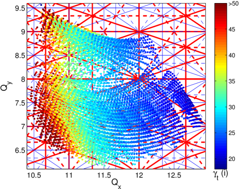
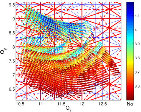
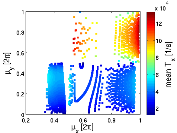
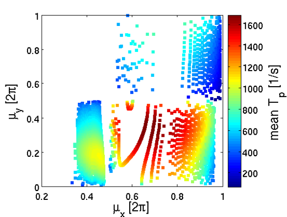
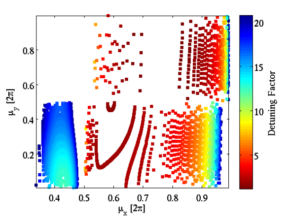
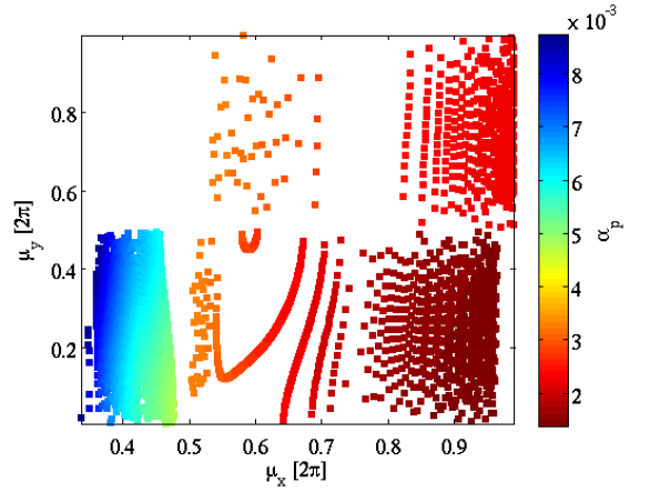
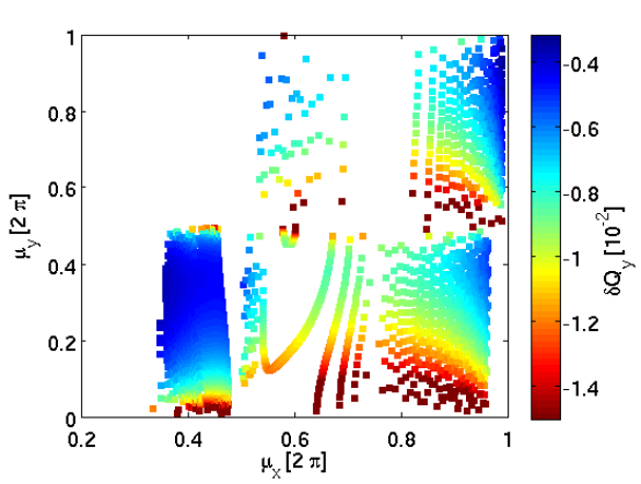
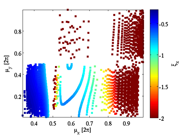
Recent optics design of high-intensity and/or high-power rings such as the J-Parc main ring [13], the PS2 [14], or the High-Power PS [15] are based on NMC arc cells, for avoiding transition and reducing losses. These are sequences of modified FODO cells with an increased number of quadrupole families (up to four) for inducing negative dispersion, leading to an overall “imaginary” [12]. In that case, the absolute value of the slippage factor could be increased for raising instability thresholds but also because a fast synchrotron frequency would be beneficial for longitudinal beam manipulation [16]. A complete picture of the achievable tuning range of a ring such as the PS2 can be obtained by the Global Analysis of all Stable Solutions (GLASS), a numerical method pioneered in low emittance rings [18], where all possible quadrupole configurations (within some gradient limits) providing stable solutions are obtained, together with the optics parameters associated to them. In the top part of Fig. 1, the imaginary transition is presented for all stable solutions in the tune diagram, along with resonance lines up to 3rd order. Low imaginary values of (i.e. large absolute values of the momentum compaction), indicated in blue are obtained for higher horizontal tunes, where there is large flexibility for the vertical tunes. In the bottom part of the figure, the geometrical acceptance is computed for the most demanding beam parameters with respect to emittance. The red colour corresponds to small acceptance (above a limit of 3.5 ), which means larger beam sizes. The trend shows that the larger sizes (red colour) are obtained for lower vertical tunes. This type of global analysis including linear and non-linear dynamics constraints was used for choosing the working point during the conceptual design of the PS2 ring, and locate it at (,)=(11.81,6.71), with [17].
4 Low Emittance Rings
The present trend of ultra-low emittance rings is to target the highest beam intensities within the smallest dimensions, at least in the transverse plane. The additional complication in the case of damping rings (DRs) for linear colliders is that they aim to produce low longitudinal emittances, as well. The output beam dimensions are largely dominated by IBS and even space-charge effects become important, especially in the vertical plane. A careful optimisation of the optics parameters is crucial for reducing these effects and obtaining a solid conceptual design [20].
4.1 Mitigating collective effects in the CLIC DRs
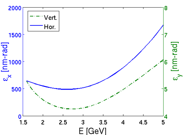
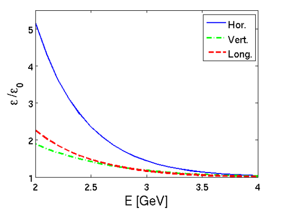
Due to the fact that not only the IBS growth rates but also the equilibrium emittances vary with energy, it is important to find their interdependence, when the IBS effect is included [21]. Evaluated through a modified version of the Piwinski method [22], and for constant longitudinal emittance, the dependence of the steady state transverse emittances of the CLIC DRs on the energy is plotted in Fig. 2 (left). A broad minimum is observed around 2.6 GeV for both horizontal (blue) and vertical planes (green). The IBS effect becomes weaker with the increase of energy, as shown in Fig. 2 (right), where the emittance blow-up for all beam dimensions is presented. Although higher energies may be desirable for reducing further collective effects, the output emittance is increased above the target value, due to the domination of quantum excitation. In this respect, it was decided to increase the CLIC DR energy to 2.86 GeV, already reducing the IBS impact by a factor of two, as compared to earlier designs at 2.42 GeV [21].
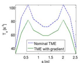
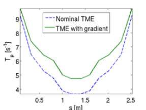
In modern low emittance rings, theoretical minimum emittance (TME) arc cells or multi bend achromats are employed. In order to reach minimum emittance, the horizontal beam optics is quite constrained, whereas the vertical one is free, but also completely determined by the two quadrupole families of the cell. It turns out that the vertical beta function reaches a minimum at the same location as the horizontal, which is the worst case for IBS. A way to reverse this tendency, is to use a combined function dipole with a low defocusing gradient. Although this gradient does not provide a significant effect to the emittance reduction, it reverses the behaviour of the vertical beta function at the middle of the dipole, maximizing the vertical beam size at that location, and thus reducing IBS growth rates [23]. This is shown in Fig. 3, where the horizontal (left) and longitudinal (right) IBS growth rate evolution are presented for a standard TME cell (blue dashed lines) and compared to the corresponding ones when the dipole includes a vertical focusing gradient (green curves). A reduction of the horizontal growth rate of almost a factor of two can be achieved in the shown example corresponding to the CLIC damping rings arc cell, by allowing a smaller increase to the longitudinal IBS growth rate.
A crucial step in the optimisation of the TME cell with respect to its impact on collective effects is the analytical derivation of the two quadrupole focal lengths, in thin lens approximation, depending only on the horizontal optics functions at the centre of the dipole and the drift space lengths [20, 24]. Using this representation, the dependence of various parameters on the cell phase advances in the case of the CLIC DRs are presented in Fig. 4, including the average IBS growth rates (top), the detuning from the minimum emittance (middle, left) the momentum compaction factor (middle, right), the vertical space-charge tune-shift (bottom, left) and the horizontal chromaticity (bottom, right). This parameterisation permitted to find the best compromise for the phase advances (between 0.4 and 0.5) where the IBS growth rates, the horizontal and vertical chromaticities and the Laslett tune shift are minimized, while the momentum compaction factor is maximized. These low phase advances correspond to emittances that deviate from the absolute minimum by a factor of around 15, as shown in Fig. 4 (middle left). Even at this large detuning factor, the TMEs are preferable for their compactness, in particular for a ring in which radiation damping is dominated by wigglers. The use of variable bends with gradient in the TME cell was also studied using a similar approach, further reducing the IBS growth rates [25].
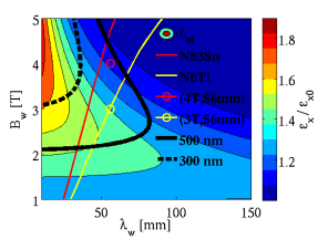
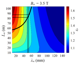
A similar study was performed in order to find the optimal wiggler field and wavelength, while minimising the IBS effect [20, 26, 27, 25]. In Fig. 5 (left), the steady state emittance ratio with the equilibrium emittance as a function of the wiggler peak field and period is presented [20, 26]. The limits for the two superconducting technologies are shown in yellow (NbTi) and red (Nb3Sn) and the 300 nm and 500 nm target steady state emittance contours in black. Based on these studies, the highest field within the limit of technology would be desirable, but a moderate wavelength is necessary for reducing IBS. At the same time, as shown in Fig. 5 (right), by raising the field and using Nb3Sn wire technology, the reduction of the ring circumference can be also achieved, with beneficial impact to all type of collective effects, including to a potential impedance reduction [27, 25]. These specifications were used for the super-conducting wiggler prototype and short model developed for the CLIC DRs [26, 27].
5 High-Brightness Synchrotrons
Hadron collider injectors need to achieve the highest brightness with the smallest possible losses. A typical example is the CERN SPS whose performance limitations and their mitigations for LHC beams are the subject of a study group [28], in view of reaching the required beam parameters for the high luminosity LHC (HL-LHC). The upgrade of the main 200 MHz RF system will solve beam loading issues for reaching higher intensities, but a variety of single and multi-bunch instabilities remain to be confronted. The transverse mode coupling instability (TMCI) in the vertical plane and e-cloud instability (ECI) for 25 ns beams are the most prominent transverse problems, especially for HL-LHC intensities. Longitudinal instabilities necessitate the use of a higher harmonic 800 MHz RF system as Landau cavity and the application of controlled longitudinal emittance blow-up throughout the ramp. For constant longitudinal bunch parameters and matched RF-voltage, higher intensity thresholds for the above instabilities are expected when increasing the phase slip factor.
5.1 Lowering transition energy in the SPS
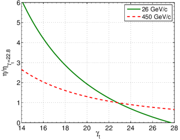
The SPS has a super-symmetry of 6 with a regular FODO lattice built of 108 cells, 16 per arc and 2 per long straight section. In the nominal SPS optics (called Q26), the phase advance per FODO cell is close to , resulting in betatron tunes between 26 and 27. Low dispersion in the long straight sections is achieved setting the arc phase advance to . Figure 6 (left) shows the optics functions in the SPS lattice for the nominal optics. The LHC-type proton beams are injected at 26 GeV/c (), i.e. above transition (). By reducing , the slippage factor is increased throughout the acceleration cycle with the largest relative gain at injection energy, as shown in Fig. 7, where normalized to the value in the nominal SPS optics () is plotted as a function of , for injection and extraction energy. Significant gain of beam stability can be expected for a relatively small reduction of , especially in the low energy part of the acceleration cycle.
In 2010, alternative optics solutions for modifying of the SPS were investigated [29]. Based on the fact that in a regular FODO lattice, the transition energy is approximately equal to the horizontal tune, can be lowered by reducing the horizontal phase advance around the ring. One of the possible solutions, with low dispersion in the long straight sections, is obtained by reducing the arc phase advance by , i.e. and the machine tunes are close to 20 (“Q20 optics”). Figure 6 (right) shows the corresponding optics functions for one super-period of the SPS. Note that in comparison to the nominal optics (“Q26”), the dispersion function follows 3 instead of 4 big oscillations along the arc with peak values increased from 4.5 m to 8 m. In this case, the transition energy is lowered from in the nominal optics to and is increased by a factor 2.85 at injection and 1.6 at extraction energy (Fig. 7). The maximum -function values are the same in both optics, whereas the minima are increased by about 50%. The optics modification is mostly affecting peak dispersion which is almost doubled. The fractional tunes have been chosen identical to the nominal optics in order to allow for direct comparison in experimental studies.
5.2 Transverse mode coupling instability
A series of measurements with high-intensity single bunches were conducted [30, 31, 32, 33] in order to quantify the benefit of the Q20 optics with respect to TMCI. In the nominal optics, the threshold is found at 1.6 p/b, for zero chromaticity, as shown in Fig. 8 (left) [33]. In order to pass this threshold with Q26, the vertical chromaticity has to be increased so much that the losses are excessive due to single-particle effects. In the Q20 optics, it was demonstrated that up to 4 could be injected with no sign of the TMCI and low chromaticity, as shown in Fig. 8 (right) [33]. Such high intensity single bunches were already sent to the LHC for beam studies [34].
5.3 Electron cloud
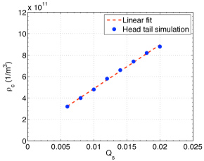
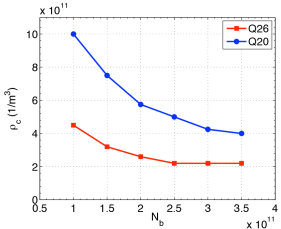
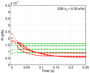
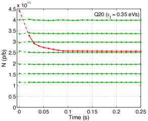
Since the ECI threshold scales with the synchrotron tune, as shown in Fig. 9 (left) [35], a clear benefit from the larger in the Q20 optics is expected. Numerical simulations were performed, assuming that the electrons are confined in bending magnets [36]. The expected threshold electron density for the ECI instability in the nominal (red) and the Q20 optics (blue), as a function of the bunch intensity at injection energy, for matched RF voltages, is presented in Fig. 9 (right). Clearly, higher thresholds are predicted for Q20.
5.4 Longitudinal multi-bunch instabilities
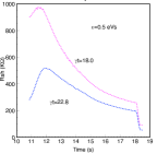
In the Q26 nominal SPS optics the longitudinal multibunch instability has a very low intensity threshold, which is decreasing with the beam energy. It is expected that for RF voltage programs providing similar beam parameters (emittances, bunch lengths) the corresponding instability threshold is higher in the Q20 optics. Figure 10 presents the calculated narrow band impedance thresholds along the cycle for both optics in the 200 MHz single RF system for a longitudinal emittance of eV.s and the corresponding voltage programs. For better comparison a constant filling factor (in momentum) is chosen. Note that the impedance threshold reaches its minimal value at flat top for both optics.
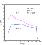
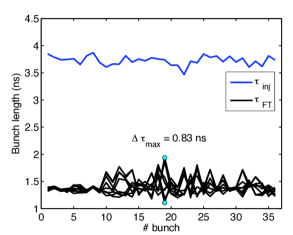
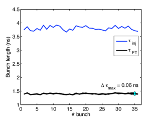
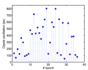
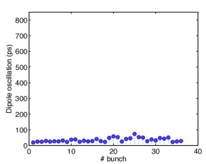
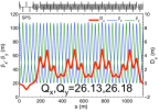
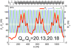
To stabilize the LHC beam at flat top in the Q26 optics, controlled longitudinal emittance blow-up is performed during the ramp, in combination with the use of a double harmonic RF system (800 MHz) in bunch shortening mode. The maximum voltage of the 200 MHz RF system is needed in order to shorten the bunches for beam transfer to the LHC 400 MHz bucket. Due to the limited RF voltage, bunches with the same longitudinal emittance at extraction will be longer in the Q20 optics. In fact, for the same longitudinal bunch parameters of a stationary bucket, the required voltage would need to be scaled with . However, the longitudinal instability threshold at 450 GeV/c is about 50% higher in the Q20 optics and therefore less or no controlled longitudinal emittance blow-up is required compared to the nominal optics, for achieving the same beam stability. Figure 11 shows a comparison of the beam stability (bunch length and bunch position) between the two optics, for one 50 ns LHC batch with p/b. The Q20 optics is stable even in the absence of emittance blow-up, with mean bunch length of around ns at flat top, which is compatible with injection into the LHC.
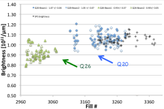
The low transition energy optics in the SPS became operational in September 2012. The switch to this new optics was very smooth, allowing very high brightness beams to be delivered to the LHC providing record luminosities [34]. An indication of the increased brightness delivered to the LHC is presented in Fig. 12, where the mean bunch intensity divided by the average of the horizontal and vertical emittance is plotted along the different LHC fills, for the second part of 2012. The green triangles represent the brightness delivered in the LHC flat bottom using the nominal Q26 optics, whereas the blue diamonds show the one corresponding to the Q20 optics, for both beams. There was a clear brightness increase at the LHC flat bottom of the order of 15 % on average, due to the Q20 optics. It is also worth noting, that the SPS brightness (black crosses) is similar, demonstrating an excellent brightness preservation between the two rings. This optics have been routinely used in operation during LHC run II (2015-2018) and opened the way for ultra-high brightness beams to be delivered in the HL-LHC era for protons and eventually for ions [37].
6 Summary
Using analytical and numerical methods, linear optics parameters, which have a direct impact on collective effects, were optimised for specific examples of high-intensity, high brightness, hadron and lepton rings. These approaches allowed a solid conceptual design of ultra-low emittance damping rings and permitted to break intensity limitations in an existing LHC injector, without any cost impact or hardware change. It is certain that there is a growing need for the optics designer to transcend the single-particle dynamics mentality and apply such optimisation procedures for reaching the optimal performance of rings, in design or operation.
7 Acknowledgements
It is a pleasure to thank G. Arduini, T. Argyropoulos, T. Bohl, H. Braun, E. Shaposhnikova, the LIU-SPS working group and the SPS operation team for invaluable contributions in several parts of this work.
References
- [1] A. W. Chao, Physics of Collective Beam Instabilities in High Energy Accelerators, New York, Wiley, 1993.
- [2] T. Argyropoulos et al., “Loss of Landau Damping for Inductive Impedance and a Double RF System”, TUPWA040, IPAC13, 2013.
- [3] W. Höfle, “Progress in Transverse Feedbacks and Related Diagnostics for Hadron Machines ”, FRXCA01, IPAC13, 2013.
- [4] P. Collier et al., “Reducing the SPS Machine Impedance”, EPAC02, WEPRI082, p.1458, 2002.
- [5] G. Rumolo, et al., “Dependence of the Electron-Cloud Instability on the Beam Energy”, PRL 100, 144801, 2008.
- [6] L. J. Laslett, “On Intensity Limitations Imposed by the Transverse Space- Charge Effects in Circular Accelerators”, BNL-7534, 1963.
- [7] A. Piwinski, in Handbook of Accelerator Physics and Engineering, ed. A. W. Chao, M. Tigner, World Scientific, p. 127, 2002; J. Bjorken, S. K. Mtingwa, Part. Accel. 13, 115, 1983.
- [8] S. Fartoukh, “Achromatic telescopic squeezing scheme and application to the LHC and its luminosity upgrade”, PRST-AB 16, 111002, 2013
- [9] J. Wei, in Handbook of Accelerator Physics, and Engineering, op. cit., p. 285. ed. A. W. Chao and M. Tigner, World Scientific, Singapore, p. 285, 2002.
- [10] T. Risselada, “Gamma transition jump schemes, 4th CAS, CERN-91-04, p. 161, 1991.
- [11] K.Y. Ng, in Handbook of Accelerator Physics, and Engineering, op. cit., p. 94. ed. A. W. Chao and M. Tigner, World Scientific, Singapore, p. 94, 2002.
- [12] S. Y. Lee, K. Y. Ng, D. Trbojevic, “Minimizing dispersion in flexible-momentum-compaction lattices”, PRE, 48(4), p. 3040, 1993.
- [13] Y. Yamazaki ed., “Technical design report of J-PARC”, KEK-2002-13, 2002.
- [14] Y. Papaphilippou et al., “Linear optics design of negative momentum compaction lattices for PS2”, TH6PFP044, PAC09, p. 3805, 2009.
- [15] Y. Papaphilippou et al., “Design Options of a High-Power Proton Synchrotron for LAGUNA-LBNO”, THPWO081, IPAC13, 2013.
- [16] S. Hancock, “Gamma at Transition of the proposed PS2 Machine”, CERN-AB-Note-2006-39, 2006.
- [17] H. Bartosik et al., “Linear Optimization and Tunability of the PS2 Lattice”, THPE022, IPAC10, 2010.
- [18] D. S. Robin, W. Wan, F. Sannibale, and V. P. Suller, “Global analysis of all linear stable settings of a storage ring lattice”, PRST-AB 11, 024002, 2008.
- [19] Y. Papaphilippou et al., “Conceptual design of the CLIC Damping Rings”, TUPPC086, IPAC12, p. 1368, 2012.
- [20] F. Antoniou, “Optics design of Intrabeam Scattering dominated damping rings”, PhD Thesis, NTUA, 2013.
- [21] F. Antoniou et al., “Parameter scan for the CLIC Damping Rings under the influence of intrabeam scattering”, WEPE085, IPAC10, p. 3542, 2010.
- [22] K. Kubo et al., “Intrabeam scattering formulas for high energy beams”, PRST-AB 8, 081001, 2005.
- [23] H.H. Braun et al., “Alternative Design of the CLIC Damping Ring Lattice”, CLIC Note 849, 2010.
- [24] F. Antoniou and Y. Papaphilippou, “Analytical considerations for linear and nonlinear optimization of TME cells. Application to the CLIC pre-damping rings”, PRST-AB 17, 064002, 2014.
- [25] S. Papadopoulou, F. Antoniou, and Y. Papaphilippou, “Emittance reduction with variable bending magnet strengths: Analytical optics considerations and application to the Compact Linear Collider damping ring design”, PRAB 22, 091601, 2019.
- [26] D. Schoerling et al., “Design and system integration of the superconducting wiggler magnets for the Compact Linear Collider damping rings”, PRST-AB 15, 042401, 2012.
- [27] L. G. Fajardo, F. Antoniou, A. Bernhard, P. Ferracin, J. Mazet, S. Papadopoulou, Y. Papaphilippou, J. Pérez and D. Schoerling, “Design of Nb3Sn Wiggler Magnets for the Compact Linear Collider and Manufacturing of a Five-Coil Prototype,” IEEE Trans. Appl. Supercond.,26 no.4, 4100506, 2016.
- [28] LIU-SPS Beam Dynamics Working Group, chaired by E. Shaposhnikova, http://paf-spsu.web.cern.ch/paf-spsu/
- [29] H. Bartosik G. Arduini, Y. Papaphilippou, “Optics considerations for lowering transition energy in the SPS”, MOPS012, IPAC11, p. 619, 2011.
- [30] H. Bartosik et al., “Experimental studies with low transition energy optics in the SPS” MOPS010, IPAC11, p. 613, 2011.
- [31] H. Bartosik et al., “Increasing Instability Thresholds in the SPS by Lowering Transition Energy”, WEPPR072, IPAC12, p. 3096, 2012;
- [32] H. Bartosik et al., “Low-gamma transition optics for the SPS: simulation and experimental results for high brightness beams”, WEO1B01, Proceedings of HB2012, Beijing, China, 2012.
- [33] H. Bartosik et al., “Experimental studies for future LHC beams in the SPS”, TUPME034, IPAC13, 2013.
- [34] Y. Papaphilippou et al., “Operational Performance of the LHC Proton Beams with the SPS Low Transition Energy Optics” THPWO080, IPAC13, 2013.
- [35] K. Ohmi and F. Zimmermann, “Head-Tail Instability Caused by Electron Clouds in Positron Storage Rings”, PRL 85, 3831, 2000.
- [36] H. Bartosik et al., “Impact of low transition energy optics to the electron cloud instability of LHC beams in the SPS”, MOPS011, IPAC11, p. 616, 2011.
- [37] F. Antoniou et al., “Considerations on SPS low-transition energy optics for LHC ion beams”, TUPME046, IPAC13, 2013.