Río Negro, Argentina,
11email: {tomas.liendro, sebastian.zudaire}@ib.edu.ar
Hybrid Control from Scratch: A Design Methodology for Assured Robotic Missions
Abstract
Robotic research over the last decades have lead us to different architectures to automatically synthesise discrete event controllers and implement these motion and task plans in real-world robot scenarios. However, these architectures usually build on existing robot hardware, generating as a result solutions that are influenced and/or restricted in their design by the available capabilities and sensors. In contrast to these approaches, we propose a design methodology that, given a specific domain of application, allowed us to build the first end-to-end implementation of an autonomous robot system that uses discrete event controller synthesis to generate assured mission plans. We validate this robot system in several missions of our target domain of application.
Keywords:
discrete event control, hybrid control, cyber-physical systems, design methodology1 Introduction
Hybrid controllers are gaining increasing attention as a way to translate discrete mission specifications into continuous motion of robots [18]. This is achieved through planning techniques that allow us to synthesise correct-by-construction discrete controllers from these specifications [25] using an adequate discrete abstraction for the robot’s capabilities and workspace. Then, a hybrid control layer [19] is responsible of interpreting these plans into a set of inputs for a lower control level that commands the robot’s motion and other functionalities. The result is an autonomous cyber-physical system guaranteed to satisfy the original specifications if a set of assumptions holds.
Hybrid controllers are possible thanks to contributions from the fields of Robotic, Control and Automated Software Engineering. On one hand, the robotic and control community studies the control and automation of continuous and discrete variable dynamic systems, developing design and implementation techniques for motion and control of robot systems [3]. On the other hand, the automated software community has developed many complex automated reasoning tools to automatically generate plans from specifications expressed in formal logic languages like Linear Temporal Logic (LTL) [1, 11].
There has been extensive research on different architectures for hybrid controllers and their implementation on functioning autonomous systems [15, 21]. In this work we focus on the inverse problem: if one were to design a robot system to implement a hybrid controller for a set of mission patterns, what would this design and implementation be?
In order to help answer this question, the main contributions of this work are: (1) a design methodology for developing assured robotic missions, (2) the first end-to-end design and implementation of an autonomous robot system that uses discrete event controller synthesis to generate assured mission plans, using the proposed methodology for a specific surveillance scenario.
For this, we build on a corpus of knowledge ranging from higher level planning problems to the lower level mechanical and hardware design, effectively building on all levels of abstraction. We show our hybrid control architecture and design methodology in Sections 4 and 5, and use it to build a surveillance robot (Section 6) that we validate in several mission scenarios (Section 7).
2 Background
We present in this section the basic formalism for the controller synthesis technique we used and basic definitions of the rest of the concepts we work with. For more insight into these concepts please refer to [24] and [12].
Labelled Transition Systems (LTS). The dynamics of the interaction of a robot with its environment will be modelled using LTS [16], which are automata where transitions are labelled with events that constitute the interactions of the modelled system with its environment. We partition events into controlled and uncontrolled to specify assumptions about the environment and safety requirements for a controller. Complex models can be constructed by LTS composition. We use a standard definition of parallel composition () that models the asynchronous execution of LTS, interleaving non-shared actions and forcing synchronisation of shared actions.
Fluent Linear Temporal Logic (FLTL). In order to describe environment assumptions and system goals it is common to use formal languages like FLTL [14], a variant of linear-time temporal logic that uses fluents to describe states over sequences of actions. A fluent fl is defined by a set of events that make it true (), a set of events that make it false () and an initial value () true () or false (): . We may omit set notation for singletons and use an action label for the fluent defined as . Thus, the fluent is only true just after the occurrence of the action .
FLTL is defined similarly to propositional LTL but where a fluent holds at a position in a trace based on the events occurring in up to . Temporal connectives are interpreted as usual: , , and mean that eventually holds, always holds, and (weakly) holds until , respectively.
Discrete Event Controller Synthesis. Given an LTS with a set of controllable actions and a task specification expressed in FLTL, the goal of controller synthesis is to find an LTS such that : (1) is deadlock free, (2) does not block any non-controlled actions, and (3) every trace of satisfies . We say that a control problem is realizable if such an LTS exists. The tractability of the controller synthesis depends on the size of the problem (i.e. states of and size of ) and also on the fragment of the logic used for . When goals are restricted to GR(1) the control problem can be solved in polynomial time [25]. GR(1) formulas are of the form where and are Boolean combinations of fluents that refer to assumptions and goals, respectively. In this paper we use MTSA [9] for solving control problems.
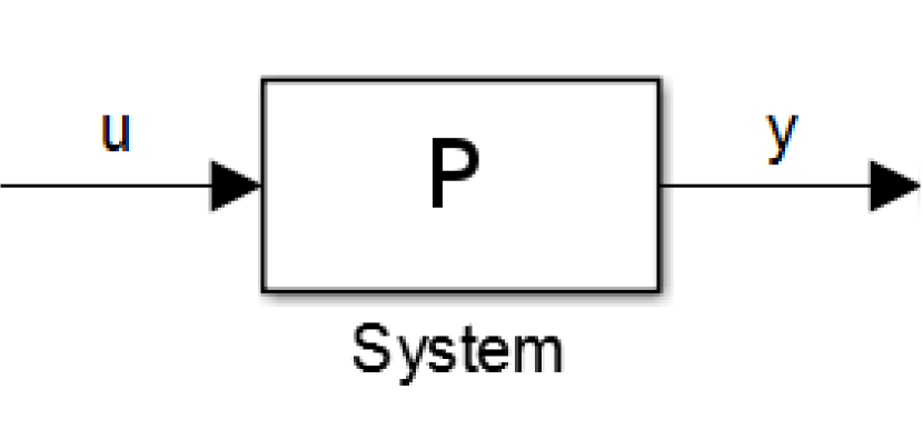
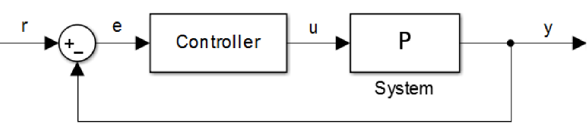
Feedback-control. Continuous variable dynamic systems (e.g., a robot wheel) can usually be abstracted into a system with a set of inputs (e.g., voltage to the motor driving the wheel) and a set of outputs (e.g., angular speed of the wheel) as shown in Fig. 1a. The typical control problem in this setting is defined as finding the set of inputs that drives the system to a certain desired configuration of the output , both in the final value of the variables as well as in the transition period, which can be approached in a open-loop or closed-loop form. Open-loop control consists of generating the set of inputs for the system from a model of the system’s behaviour. This approach doesn’t take into account errors in the model or external perturbations to the system. A more robust approach is closed-loop control (i.e., feedback-control), which uses direct or filtered measurements of the output to compute the input that helps minimise the error (see Fig. 1b), according to a set of specifications.
Hybrid Controller. In robotics, the difference in the continuous vs. discrete description of the real world, and in the interaction between discrete event controllers and feedback-controllers (or other robot actuators and sensors) require a non-trivial translation task that is implemented in a hybrid control layer [1, 10].
To implement these plans, the hybrid control layer is responsible of taking high-level commands (e.g., the camera.on action from [18]) and generating low-level inputs for the robot (e.g., a low-level voltage pulse train to trigger the camera into capture mode). When this translation is specifically related to motion, there is extensive work in the area of motion planning (e.g., [2, 6, 8]). Translating motion commands into continuous movement generally involves obtaining a set of discrete inputs that serve as a reference signal for the feedback-controllers, which then produce controlled movement of the robot [10].
3 Related Work
The design of hybrid control architectures for end-to-end implementations, i.e., that integrate components ranging from planning to robot hardware, has been approached by many (e.g., [1, 10, 18, 19, 15, 21]). However, this process usually begins with partially or fully functional low-level robot hardware and software (e.g., [15]). In these scenarios the design problem consists in finding a discrete abstraction for the planning layer that captures the robots capabilities and workspace [21], and that is compatible with the desired domain of application. The key challenge is that the state space of the chosen abstractions must not be too big so as lead to intractability of the synthesis problem (e.g., increasing number of discrete locations leads to polynomial growth in synthesis time [7]), nor too small so as to fail to capture important aspects from the continuous environment of the robot (e.g., the abstraction problems presented in [8]).
To the best of our knowledge, our work is the first to tackle the design of hybrid controllers as a whole, with the distinctive feature of building a custom robot that accommodates to various choices made during the design process.
4 Component Architecture
To approach an end-to-end design, we must first define a component architecture to identify the different elements of the system and their interaction. We build on several architectures taken from the control [13], robotic [19] and software communities [4] to define the architecture shown in Fig. 2, where arrows indicate interaction between components. We will describe this architecture using an alternative font when referring to elements in Fig. 2.
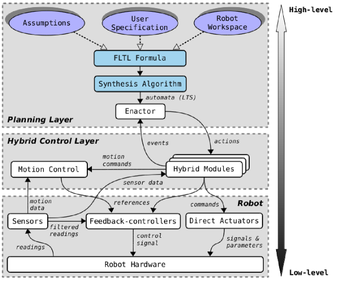
Planning Layer: This layer uses as an input high-level abstractions of the environment in which the robot moves and interacts. This input can be divided into a Robot Workspace that provides a discretized notion of the capabilities of the robot (see Section 6.1), a set of Assumptions about the robot’s environment and capabilities (e.g., a camera.on action can only be followed by a camera.off) and a User Specification that captures what the mission for the robot is. All these elements can be encapsulated into a FLTL Formula and then use a Synthesis Algorithm to produce a correct-by-construction discrete event controller guaranteed to satisfy mission, which is represented as an automata in LTS.
A component is then required to interpret the plan encoded in its LTS representation. The Enactor consists of an interpretation module that knows which module to call from the available Hybrid Modules each time controllable actions are enabled in the plan, and continuously listens for discrete events that may be triggered during the mission.
Hybrid modules: These modules provide the main translation process between the continuous and discrete representations of the environment. To implement certain discrete actions, references may be trivially computed at this level and sent to the Feedback-controllers (e.g., to implement a drill.fast action, the reference angular speed of a feedback-controller controlling the drilling speed may be set to ). For other actions, the Hybrid Modules may command a Direct Actuator (e.g., turning on a led). The process becomes more complicated for motion capabilities, so a Motion Control or motion planner module may be used to provide additional computation from the available motion data to generate a set of references for the Feedback-controllers. From the available sensor data, discrete events may be generated.
Robot: This layer includes the physical Robot Hardware as well as modules that provide the basic capabilities of the robot through Feedback-controllers and Direct Actuators. The difference between these two is that due to its closed-loop nature, the first require filtered readings from the Sensors to generate control signals.
5 Design Methodology
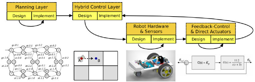
In Fig. 3 we show our methodology through the system design and implementation. Comparing with Fig. 2, the design flows from the highest levels of abstraction to the lowest, but the final component to be implemented is the Hybrid Control Layer. Next we describe each stage of the process with more detail:
Planning Layer: Our design methodology is guided by the desired domain of application, this means that we must first ensure that, for the missions we wish to specify and run, we have a compatible discrete abstraction and tractable synthesis algorithm. For example, common patrol or surveillance missions [8, 23] may be reasonably abstracted using grid-based discretization of the movement region of the robot, i.e., workspace. Multiple synthesis algorithms have shown tractability for this kind of specifications and abstractions (e.g., [11, 27]), meaning that this is a reasonable approach for this family of missions. At this stage we both design the Planning Layer and implement it by synthesising missions and eventually enacting them in dummy environments.
Hybrid Control Layer (design): When the discrete abstraction is defined, we must provide a hybrid controller and robot hardware capable of implementing it. Common approaches usually involve using available working robot hardware on top of which they define a hybrid control architecture (e.g., [15]), but has the downside of incurring in complex architectures and components as a result. For instance, if we build on a common car-like robot, movement from one point to another will require at the very least the computation of a Dubins path or Reeds-Shepp path [17]. For certain space discretizations, this may also require sophisticated resynthesisation loops to find feasible trajectories (see [8]). All this added complexity could have been avoided by selecting more adequate hardware for movement in a 2D plane such as omnidirectional wheels [26].
Our hypothesis is that many simplifications can be made by continuing the design process at the hybrid control layer. Designing the robot motion capabilities will require first designing a motion planning or motion control strategy to move the robot according to the discrete abstraction used. The same goes for other capabilities that require controlled command of the actuators.
Robot Hardware & Sensors: Once reasonable motion and actuator strategies have been designed for the hybrid control layer, only the bottom low-level robot-related components are left. Robot hardware and sensors must be selected to comply with the design requirements defined during the previous stage.
Feedback-Control & Direct Actuators: When the previous stage is implemented, the design of feedback-controllers and other actuators can commence, since they both require a real robot in which to validate their control algorithms.
Hybrid Control Layer (implement): The final stage of the methodology involves integrating all the components into a fully working hybrid controller. For this, several Hybrid Modules must be implemented as well as the Motion Control strategy designed earlier.
6 Example Use of the Design Methodology
In this section we use the design methodology described in Section 5 to build a robot system for a surveillance mission scenario.
6.1 Planning Layer
We first have to define our domain of application, i.e., the missions we want to do. The work in [23] provides common mission specification patterns found in the robotic literature, from which we aim to achieve all the Core Movement Patterns (visiting and patrolling), Avoidance patterns (prohibited regions) and the Reaction patterns (e.g., turning on a camera when inside a region). We will work with low duration missions ( ) on a small 2D plane (approx. ) and restrict the reaction patterns into an alert with sound and leds.
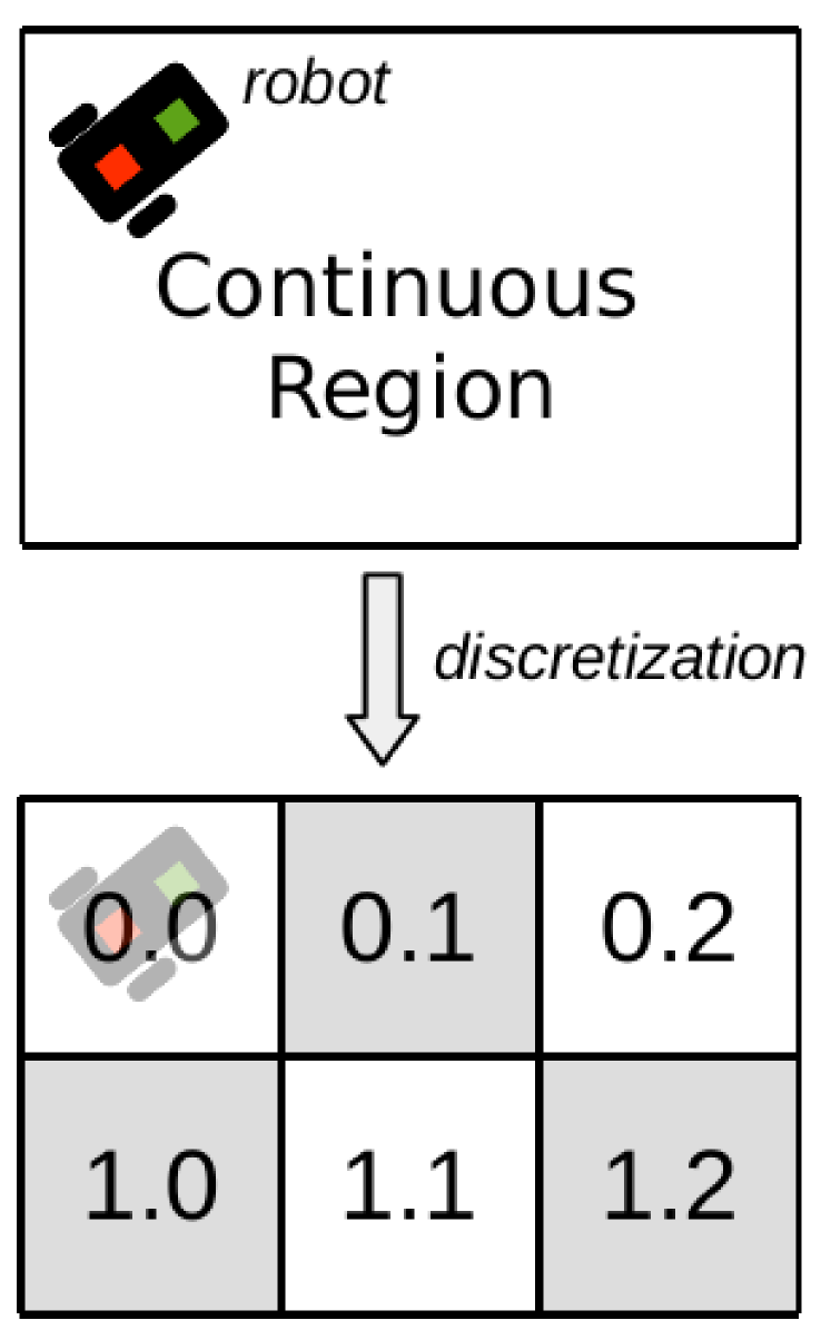
For surveillance and visiting missions, its common to use space discretization of the robot’s workspace [1]. As the robot will be performing its tasks in an rectangular area, it is reasonable to discretize the robot’s working area by using an uniform rectangular grid containing cells as in [27]. The minimum size of the cells is limited by the ability of the robot to move fully contained in it while manoeuvring to the next [2]. This allows us to avoid discrete regions by specifying at the planning level never to take transitions that lead to prohibited regions. Furthermore, we must only allow movement to adjacent cells, since moving in diagonal may lead to entering forbidden cells along the way.
Fig. 4a and 4b show how we derive from the grid-based discretization of a region a LTS modelling the motion behaviour of the robot. We abstract motion into two actions: a controllable go.i.j action to command the robot to move to the discrete location of the grid, and the respective uncontrollable at.i.j event to indicate that the robot arrived correctly at this location. This LTS also includes certain assumptions about the movement of the robot: a go.1.2 action can only be followed by a at.1.2 event and between go.i.j and at.i.j no other go can be issued. For the alert capability we may use a simple LTS abstraction as shown in Fig. 4c, where each controllable action is modelled as instantaneous. The environment consists of the parallel composition of these two LTS.
We will use FLTL formulae to specify missions. For example, a patrol mission between the discrete locations and , where the robot must turn on its alert in the bottom row locations and turn it off in the top row, and always avoid location , can be specified with the fluents defined in (1) and the formula . This formula relates to the Patrolling (), Global avoidance () and Prompt Reaction () patterns in [23].
| AtBot | (1) | |||
| AtTop | ||||
| Alert |
| (2) | ||||
We used the MTSA tool to solve the control problem derived from the environment and the above specifications. This tool proved tractability on low-end hardware (see Section 6.3) for hundreds of discrete locations. We use the obstacle sensor described in Section 6.3 to automatically specify locations to avoid ().
An Enactor for these plans was implemented by parsing the output discrete event controllers generated with MTSA into an equivalent data structure in Python to be able to integrate with the modules in the hybrid layer. A queue mechanism allows it to run as an independent process, calling the controllable actions of the plan (implemented in the Hybrid Modules) as they are enabled and immediately processes any uncontrollable event that may be generated.
6.2 Hybrid Control Layer Design
Our target domain of application requires developing movement and non-movement (i.e., alert capability) functionality for the robot. Implementing an alert capability is pretty straight forward for simple temporised alarms. However, commanding movement of the robot is not, so we will focus on its design process.
Given the discrete abstraction we defined in Section 6.1 that handles at the higher level static-obstacle avoidance, our motion planning problem reduces to finding a set of control inputs for the robot to go from one discrete location to an adjacent one. This simple problem can be solved without relying on sophisticated motion planners (e.g., RRT [5]) using either omnidirectional robots or with a motion control solution over an unidirectional moving robot. The first solution (e.g., [26]) just pushes the complexity and cost of the problem to a lower level. Here we show that a carefully selected simple motion control strategy can simplify the design and implementation process of the lower mechanical and hardware level, as stated in Section 5.
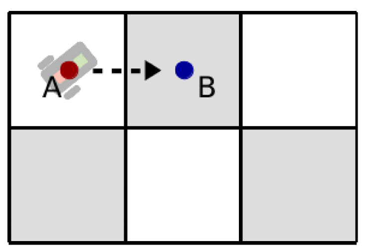
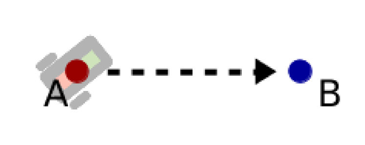
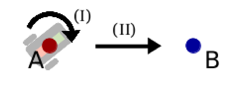
The motion problem is illustrated in Fig. 5a, were we see the robot wanting to do a transition through a go action to an adjacent cell. The abstracted motion planning problem is shown in Fig. 5b and a very simple solution to this problem is presented in Fig. 5c for an unidirectional moving robot:
-
(I)
Rotate until the “front” of the robot points in the direction of the target.
-
(II)
Move forward along this direction until the target is reached.
This type of motion control solution requires both a robot with a unidirectional forward moving capability and the functionality of rotating around its centre axis (i.e., without displacement of its centre of mass), which can be easily satisfied and implemented with a low-cost two-wheel robot as in [3, 20, 22].
6.3 Robot Hardware and Sensors
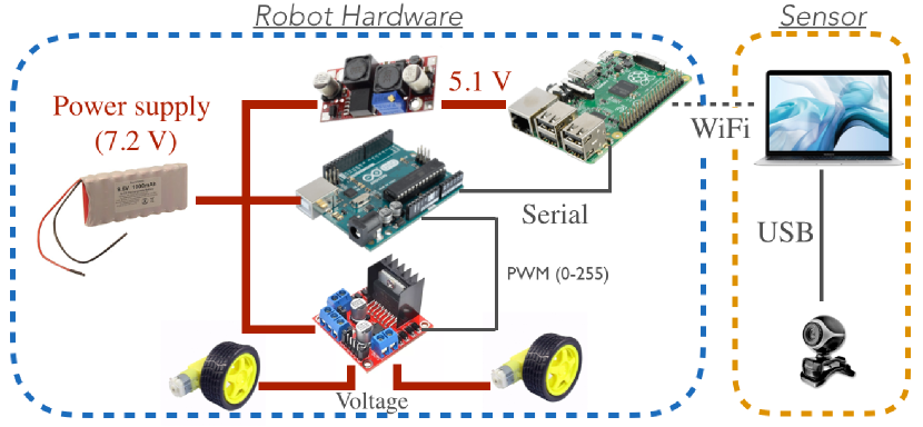
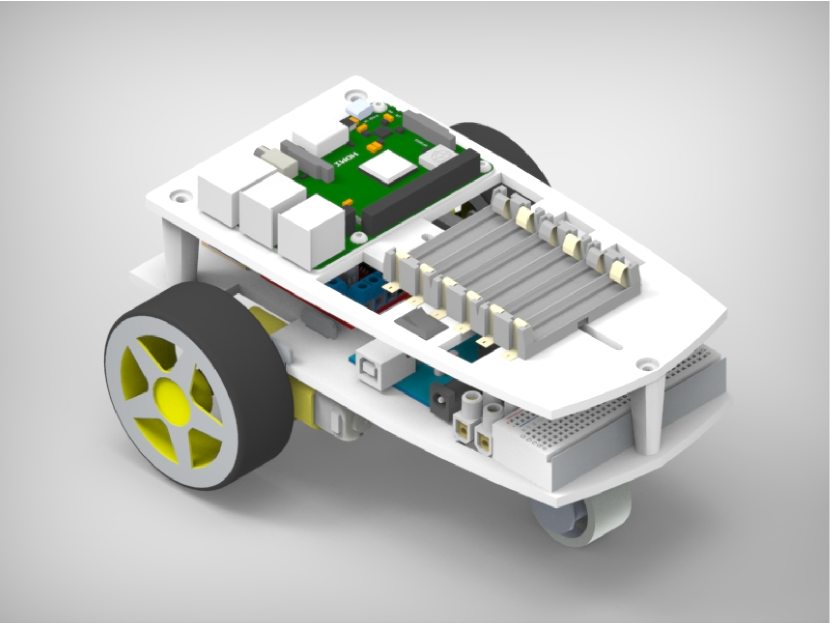
In Fig. 6a we show an overview for our Robot Hardware and Sensor solution. We selected a simple two-wheeled solution as the robot platform, similar to [22], where we use a third pivoting wheel to have a stable platform (see Fig. 6b) and avoid incurring in self-balancing control algorithms as in [20]. We defined the size and shape of the robot to be able to accommodate all the electronic and hardware components and have easy access to the battery.
A simplified connection schematics for the robot design is shown in Fig. 6a. Due to the motion control algorithm defined in Section 6.2 we require independent motors to drive the wheels, for which we selected common DC motors and an H-bridge to command them. An Arduino UNO board was used to communicate with the H-bridge, and to later implement the low-level feedback- and motion control logic. For synthesising and enacting the discrete event controllers, and implementing the image processing modules we included a Raspberry Pi 3B+ single-board computer. For power we used 6 AA rechargeable batteries (with a voltage regulator for the Raspberry Pi), generating an autonomy of over 1 hour. Finally, for the alarm capability we connected to the Arduino leds and a speaker to produce audible noise (not shown in Fig. 6a).
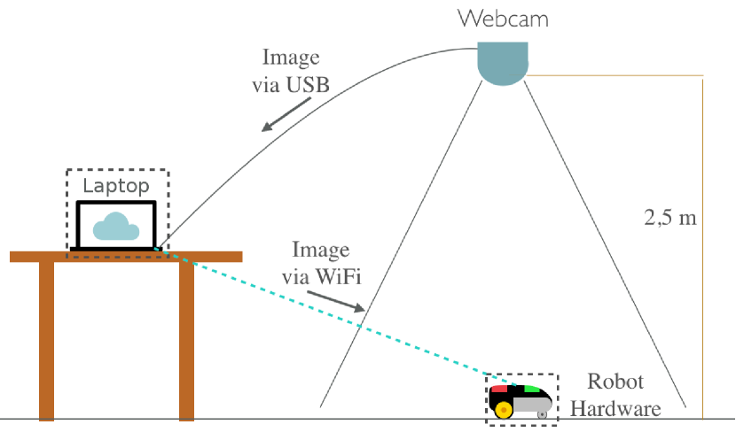
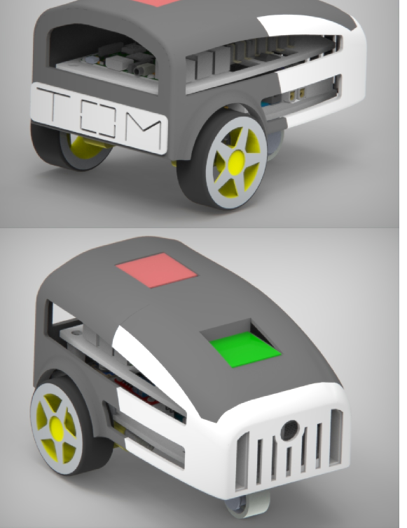
Our motion control algorithm requires to sense both the position and heading of the robot, as well as automatic detection of static obstacles for the planning layer. Since we are planning to do missions on the footprint of around (e.g., the floor of a small room), we used a camera mounted on the ceiling to track the movement. We added color tags on top of the robot (see Fig. 7b) and used blue obstacles to automatically detect from the images: position and orientation of the robot and discrete regions that include obstacles. The images from the ceiling-cam are transmitted via USB to an intermediary laptop and then via WiFi to the onboard computer (see Fig. 7a), to be later processed onboard.
6.4 Feedback-controllers and Direct Actuators
For the alert system we implemented the following Direct Actuator: a function on the Arduino that turns on the leds and the beeping noise depending on the value of a input flag from the serial port.
For the motion capabilities we used a Feedback-controller for orientation and an open-loop controller for forward movement. The latter is fairly straightforward to implement if we don’t want a controlled velocity: we implemented at the Arduino level a function to set the wheels into a forward movement through a constant PWM signal for both wheels. This controller does not guarantee that the robot will follow a straight path given that, due to slipping or friction, a tendency to turn can be present. We simply ignore this problem and expect the orientation controller to fix the heading of the vehicle as it moves.
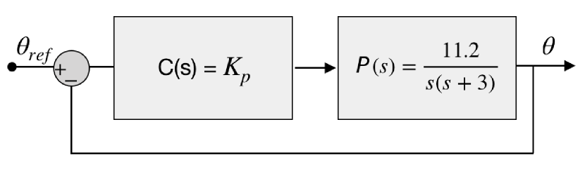
Based on [12], to design the feedback-controller we must first develop a model of the dynamics of the system. In [12], a mathematical model is proposed with a simplified electrical circuit and mechanical forces. Thus, we obtained the dynamical model (Laplace transformed) of the system shown in (3), where we group the many circuit and mechanical related constants () into and , is the orientation of the robot and is the applied voltage to the motors (with different signs for each one).
| (3) |
Fig. 8a shows the identified parameters and using standard identification control techniques. This system can be reasonably controlled using a proportional controller as shown also in Fig. 8a, where .
6.5 Hybrid Control Layer Implementation
As recognised in [8], discretization for synthesis problems must take into account the actual ability of the robot to transverse from a discrete cell to the next without invading nearby cells in the process. The main limitation of the motion control strategy is at the feedback-control and hardware level, where from experimental data we estimated that the robot requires 15 pixels (i.e., ) of turn radius to be able to rotate, mainly because it doesn’t properly rotate around its centre of mass. This makes us set the cell size for the discretization at 60 pixels (i.e., ), and as result gives us a rectangular grid of cells for the workspace defined by the mounted camera (see Fig. 7a).
The final step of our design methodology is implementing the different modules in the Hybrid Control Layer. The developed modules were implemented in Python 3.4 onboard the vehicle and behave as follows:
Alert Module: This module interprets the alert.on and alert.off commands and sets the flag described in Section 6.4 accordingly.
Motion Handler Module: The motion handler takes as an input go.i.j and translates it into a continuous position (in units of distance) to later command the Motion Control component. It also detects from the available sensor data that the target discrete location has been reached, i.e., the robot’s position is less than 15 pixels (i.e., ) from the centre of the discrete location, and outputs the discrete event at.i.j to the Enactor.
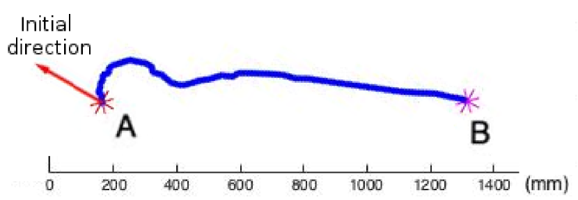
Motion Control: This module implements the algorithm described in Section 6.2, generating trajectories for the robot as shown in Fig. 8b. Since the forward movement is generated through open-loop control, this module also switches between the rotating and forward motion capabilities, to keep the robot pointing to the target location. Part of this logic is implemented on the Arduino.
7 Experimentation and Validation
We validated the correct behaviour of the designed robot by testing it in three different missions taken from its domain of application (see Section 6.1). The videos and the full FLTL specifications from which the discrete event controllers were synthesised can be found in the supplementary material.
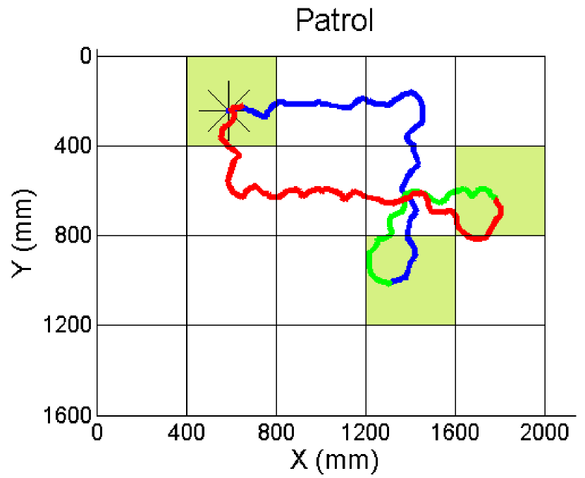
Our first validation mission was a simple surveillance of three areas. For this we selected three areas to visit infinitely often (see Fig. 9a) and used a similar specification to in equation (2) adjusted to these three locations. This mission allowed us to test the correct behaviour of the overall system and analyse the paths generated by the motion control strategy. We run the synthesised controller on the vehicle, and it generated as a result the trajectory shown in Fig. 9a, successfully doing a full patrol loop around the three locations.
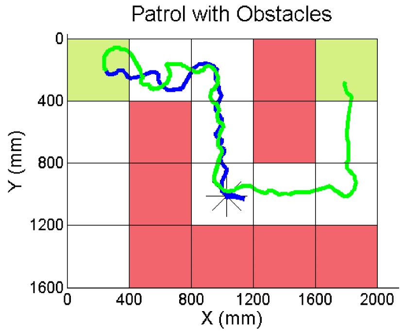
For our second mission we chose to validate our automatic detection of obstacles. We chose for this a patrol mission of two areas as shown in Fig. 9b and included in the workspace several blue objects, that we can automatically detect with simple image filtering techniques and tag them as locations to avoid with a similar specification as in equation (2). Fig. 9b shows that the robot successfully visits the two locations while avoiding the red areas.
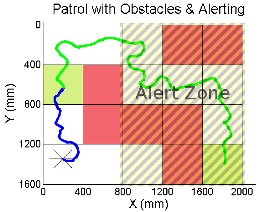
Finally, we tested the alert system by synthesising a mission similar to the last one but turning on the alarm sounds and leds while in the regions shown in Fig. 9c, using similar specification as of (2). Fig. 9c shows the resulting path for this mission. Note that although the path followed by the robot is quite curvy at times, it successfully accomplishes the mission it was designed for.
8 Conclusions and Future Work
In this work we presented a design methodology and effectively used it to build a robot system that successfully accomplishes a set of missions taken from a surveillance domain of application. For this, we built on discrete event controller synthesis techniques which allowed us to generate plans that are guaranteed to accomplish high-level mission specifications if a number of assumptions about the robot’s capabilities and workspace hold. We validated our system by running three increasingly complicated tasks that involved both motion, obstacle avoidance and the non-movement functionality of an alarm system.
In future work it would be interesting to incorporate into the domain of application the use of more complex actuators (e.g., manipulating capabilities) to see if the presented methodology is helpful in these scenarios. Another aspect is to focus on improving the motion paths described by the robot, analysing the balance between more sophisticated motion control/planning, more robust feedback-controllers and different hardware/mechanical designs.
References
- [1] C. Belta, A. Bicchi, M. Egerstedt, E. Frazzoli, E. Klavins, and G. J. Pappas. Symbolic planning and control of robot motion [grand challenges of robotics]. IEEE Robotics Automation Magazine, 14(1):61–70, 2007.
- [2] C. Belta and L. C. G. J. M. Habets. Constructing decidable hybrid systems with velocity bounds. In 2004 43rd IEEE Conference on Decision and Control (CDC), volume 1, pages 467–472 Vol.1, 2004.
- [3] X. Bin, G. Lei, W. Shimin, S. Yuan, and Z. Ying. Dynamics modeling and system parameter identification experiment of a kind of two-wheeled robot. In 2015 IEEE International Conf. on Information and Automation, pages 404–408, Aug 2015.
- [4] Victor Braberman, Nicolas D’Ippolito, Jeff Kramer, Daniel Sykes, and Sebastian Uchitel. Morph: A reference architecture for configuration and behaviour self-adaptation. New York, NY, USA, 2015. ACM.
- [5] S. Carpin and Enrico Pagello. On parallel rrts for multi-robot systems. Proc. 8th Conf. Italian Association for Artificial Intelligence, pages 834–841, 01 2002.
- [6] D. C. Conner, A. A. Rizzi, and H. Choset. Composition of local potential functions for global robot control and navigation. In Proceedings 2003 IEEE/RSJ Int. Conf. on Intelligent Robots and Systems, volume 4, pages 3546–3551 vol.3, Oct 2003.
- [7] S. Dathathri and R. M. Murray. Decomposing gr(1) games with singleton liveness guarantees for efficient synthesis. In 2017 IEEE 56th Annual Conference on Decision and Control (CDC), pages 911–917, 2017.
- [8] J. A. DeCastro, V. Raman, and H. Kress-Gazit. Dynamics-driven adaptive abstraction for reactive high-level mission and motion planning. In 2015 IEEE International Conference on Robotics and Automation (ICRA), pages 369–376, 2015.
- [9] Nicolás Roque D’Ippolito, Victor Braberman, Nir Piterman, and Sebastián Uchitel. Synthesis of live behaviour models. In Proceedings of the 18th ACM SIGSOFT Symposium on the Foundations of Software Engineering, pages 77–86, USA, 2010.
- [10] G. E. Fainekos, H. Kress-Gazit, and G. J. Pappas. Temporal logic motion planning for mobile robots. In Proceedings of the 2005 IEEE International Conference on Robotics and Automation, pages 2020–2025, 2005.
- [11] C. Finucane, Gangyuan Jing, and H. Kress-Gazit. Ltlmop: Experimenting with language, temporal logic and robot control. In 2010 IEEE/RSJ International Conference on Intelligent Robots and Systems, pages 1988–1993, Oct 2010.
- [12] Gene F. Franklin, J. David Powell, and Abbas Emami-Naeini. Feedback Control of Dynamic Systems. Addison-Wesley, USA, 3rd edition, 1994.
- [13] Gan Yong, Sun Yushan, Wan Lei, and Pang Yongjie. Motion control system architecture of underwater robot. In 2006 6th World Congress on Intelligent Control and Automation, volume 2, pages 8876–8880, June 2006.
- [14] Dimitra Giannakopoulou and Jeff Magee. Fluent model checking for event-based systems. ESEC/FSE-11, pages 257–266, New York, NY, USA, 2003. ACM.
- [15] Gangyuan Jing, Tarik Tosun, Mark Yim, and Hadas Kress-Gazit. An end-to-end system for accomplishing tasks with modular robots: Perspectives for the ai community. In Proceedings of the Twenty-Sixth International Joint Conference on Artificial Intelligence, IJCAI-17, pages 4879–4883, 2017.
- [16] Robert Keller. Formal verification of parallel programs. Communications of the ACM, 19:371–384, 07 1976.
- [17] J. M. Kim, K. I. Lim, and J. H. Kim. Auto parking path planning system using modified reeds-shepp curve algorithm. In 2014 11th International Conference on Ubiquitous Robots and Ambient Intelligence (URAI), pages 311–315, Nov 2014.
- [18] H. Kress-Gazit, G. E. Fainekos, and G. J. Pappas. Temporal-logic-based reactive mission and motion planning. IEEE Trans. on Robotics, pages 1370–1381, 2009.
- [19] Hadas Kress-Gazit, Georgios Fainekos, and George Pappas. Translating structured english to robot controllers. Advanced Robotics, 22:1343–1359, 10 2008.
- [20] T. A. Mai, T. S. Dang, D. N. Anisimov, and E. Fedorova. Fuzzy-pid controller for two wheels balancing robot based on stm32 microcontroller. In 2019 International Conf. on Engineering Technologies and Computer Science, pages 20–24, 2019.
- [21] S. Maniatopoulos, P. Schillinger, V. Pong, D. C. Conner, and H. Kress-Gazit. Reactive high-level behavior synthesis for an atlas humanoid robot. In 2016 IEEE International Conf. on Robotics and Automation (ICRA), pages 4192–4199, 2016.
- [22] Augusto Masetti and Lucas Terissi. Prototype robot for computer vision and control systems applications. In Concurso de Trabajos Estudiantiles - JAIIO 46, pages 37–46, Sep 2017.
- [23] C. Menghi, C. Tsigkanos, P. Pelliccione, C. Ghezzi, and T. Berger. Specification patterns for robotic missions. IEEE Trans. on Soft. Engineering, pages 1–1, 2019.
- [24] L. Nahabedian, V. Braberman, N. D’Ippolito, S. Honiden, J. Kramer, K. Tei, and S. Uchitel. Dynamic update of discrete event controllers. IEEE Transactions on Software Engineering, pages 1–1, 2018.
- [25] Nir Piterman, Amir Pnueli, and Yaniv Sa’ar. Synthesis of reactive (1) designs. Lecture notes in computer science, 3855:364–380, 2006.
- [26] R. Wen and M. Tong. Mecanum wheels with astar algorithm and fuzzy pid algorithm based on genetic algorithm. In 2017 International Conference on Robotics and Automation Sciences (ICRAS), pages 114–118, Aug 2017.
- [27] E. M. Wolff, U. Topcu, and R. M. Murray. Efficient reactive controller synthesis for a fragment of linear temporal logic. In 2013 IEEE International Conference on Robotics and Automation, pages 5033–5040, May 2013.