Further author information: (Send correspondence to Benjamin Dawson)
Benjamin Dawson: E-mail: py13bhd@leeds.ac.uk
Spontaneous emission of atomic dipoles near two-sided semi-transparent mirrors
Abstract
Atom-field interactions near optical interfaces have a wide range of applications in quantum technology. Motivated by this, this paper revisits the spontaneous emission of atomic dipoles in the presence of a two sided semi-transparent mirror. First we review the main properties of the quantised electromagnetic field near a semi-transparent mirror. To do so, we employ a quantum mirror image detector method which maps the experimental setup which we consider here onto analogous free space scenarios. We emphasise that the local density of states of the electromagnetic field depends on the reflection rates of both sides of the mirror surface. Hence it is not surprising that also the spontaneous decay rate of an atomic dipole in front of a semi-transparent mirror depends on both reflectance rates. Although the effect which we describe here only holds for relatively short atom-mirror distances, it can aid the design of novel photonics devices.
1 Introduction
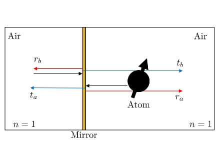
Recent technological developments in silicon photonics encourage the design of novel devices with a wide range of applications in quantum technology [1, 3, 2]. For example, devices which utilize the sensitivity of an atomic dipole’s fluorescent properties to its respective environment have potential applications in quantum sensing [4]. Motivated by these developments, this paper reviews a quantum mirror image detector method which can be used to model the quantised electromagnetic field in the presence of optical interfaces for a wide range of experimental parameters [5, 6]. The experimental set up which we consider here is shown in Fig. 1 and consists of an atomic dipole placed near a two-sided semi-transparent mirror. In the following, we describe the mirror surface by its reflection and transmission rates , , and with
| (1) |
with indices and referring to wave packets approaching the mirror form the left and from the right, respectively. For simplicity, we neglect the possible absorption of light in the mirror surface, the presence of evanescent field modes as well as any dependence of the reflection and transmission rates on angle, frequency and polarization of the incoming light.
The modelling of atom-field interactions near highly-reflecting mirrors and dielectric media already attracted a lot of attention in the literature (see e.g. Refs. [7, 9, 10, 11, 20, 12, 13, 14, 17, 18, 16, 19, 21, 5, 22, 6, 15, 8]). The most common method of modelling the electromagnetic field in the presence of a semi-transparent mirror is the triplet-mode model by Carniglia and Mandel [9]. Its basic idea is to assume that the electromagnetic field contains only stationary energy quanta with accordingly-weighted incident, reflected and transmitted components. When using this approach to calculate atomic decay rates in the presence of an optical interface, predictions closely match experimental data (see e.g. Refs. [23, 24, 25, 26]). However, when modelling light incident onto a semi-transparent mirror from both sides, the triplet-mode model leads to unphysical interference effects [19, 21]. Light reflection by optical mirrors still needs to be studied in more detail [22].
 |
There are different ways of avoiding the above mentioned interference problem. For example, one can adopt the input-output formalism [12, 13], so-called universe mode models [20] or assume that the electromagnetic field contains positive as well as negative frequency components [16, 21, 22]. Unfortunately, the consistency of these different approaches has not yet been shown. In this paper we therefore adopt an alternative approach—a quantum mirror image detector method [5, 6]. Inspired by the method of mirror images in classical electrodynamics, this method maps the dynamics of wave packets scattering from a semi-transparent mirror onto analogous free space scenarios, thereby avoiding the question of how to describe the mirror surface. We then use this approach to calculate the spontanous decay rate of an atomic dipole in the presence of a two-sided semi-transparent mirror. As we see below, this rate depends on both reflection rates, and , of the mirror interface.
This paper comprises of four sections. In Section 2 we review the main results of Refs. [5, 6] and describe the main assumptions made in the derivation of the electric field observable for the experimental setup which is shown in Fig. 1. Section 3 presents an expression for the corresponding atomic decay rate and illustrates its dependence on the atom-mirror distance and other mirror parameters. Lastly, Section 4 contains a summary of our findings and discusses their implications.
2 The quantum mirror image detector method
To model the experimental setup in Fig. 1, we map the dynamics of incoming wave packets onto the dynamics of wave packets in analogous free space scenarios [5, 6]. To do so, we distinguish between wave packets originating on the left hand side and wave packets originating on the right hand side of the mirror interface. Placing the mirror surface at , both cases correspond to and , respectively. In the following, we label the corresponding electric field contributions by superscripts and . Moreover we assume that wave packets travel as they do in free space, i.e. as predicted by Maxwell’s equations in the absence of any reflecting surfaces.
In the presence of the semi-transparent mirror shown in Fig. 1, the transmitted part of an incoming wave packet propagates exactly as it would in free space. However, the reflected part will eventually be found at a position instead of arriving at the position of the transmitted field. According to the quantum mirror image detector method, the general solution of the classical electric field in the presence of a semi-transparent mirror at a position and at a time is therefore of the form [5, 6]
| (2) | |||||
with and with the Heaviside step function given by
| (5) |
Moreover, with and is a free space solution of Maxwell’s equations with the same initial conditions as . The superscripts (a) and (b) indicate whether an incoming wavepacket approaches the mirror from the right or from the left, respectively. Finally, the phase factors in Eq. (2) are free parameters which can be used to model phase factor changes of incoming wave packets upon reflection and transmission. Note that these phase factors need to obey the condition
| (6) |
where is an integer, to ensure that energy is preserved [5, 6].
Modelling the experimental setup in Fig. 1 from a quantum optics perspective is made difficult by the fact that its electromagnetic field is not a closed system and does not evolve independent of the mirror surface [5, 6]. However, demanding that electric and magnetic field expectation values evolve exactly as predicted by classical electrodynamics, one can show that the observable of the electric field at a position need to be of the form [5, 6]
| (7) | |||||
where denote the observable of the electric field in free space. As before, the superscripts and indicate whether a wave packet originates from the right or from the left half space of the mirror, respectively. Since the quantum mirror image detector method requires that we measure the photons incident on either side of the mirror differently means our mapping onto analogous free space scenarios is only possible, if we effectively double the Hilbert space of the electromagnetic field. Other papers also emphasise the need for such a doubling [16, 21, 22].
 |
The parameters and in Eq. (7) are normalisation factors. Unfortunately, these cannot be determined, as usual, by simply assuming that a photon of frequency has the energy . The reason for this is that the energy of the system resides not only in the electromagnetic field. Some of it is contained in the mirror surface (for more details see Ref. [5]). Currently, these are calculated by demanding that the spontaneous decay rate of an atom interacting with the electric field in Eq. (7) reduces for relatively large atom-mirror distances to its respective free space value . From this we get
| (8) |
and following the procedure given in Refs. [5, 6], we find that the normalisation factors and are given by
| (9) |
providing the mirror surface does not absorb energy from the electromagnetic field. As a result of such a locality condition, the local density of states of the electromagnetic field in the immediate vicinity of the mirror surface differs in general from what it would be in the absence of an interface [5, 6]. Near the plane, it depends on the reflection rates and of both sides of the mirror interface.
3 Atomic spontaneous decay rates
|
Proceeding as described in Refs. [5, 6], the electric field observable in Eq. (7) can be used to show that the spontaneous decay rate in the presence of a two-sided semi-transparent mirror equals
| (10) |
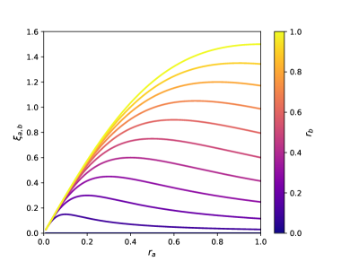
to a very good approximation. Here, the value in Eq. (10) is a mirror parameter, which depends on the rate of reflection of either side of the mirror,
| (11) |
As shown in Fig. 2, this parameter varies between 0 and 1.5. Moreover, the parameter in Eq. (10) is the wave number of the emitted light and is the -component of the normalised atomic transition dipole moment and varies between 0 and 1.
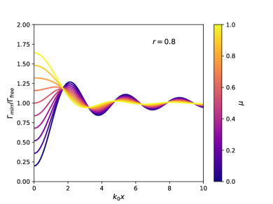 |
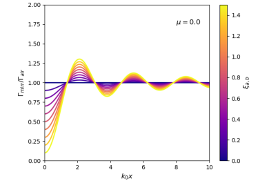
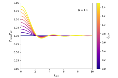
Finally, Fig. 3 shows the dependence of on the atom-mirror distance for different mirror parameters and for two different values of . It can be seen that the atomic lifetime has an oscillatory variation with distance. From Fig. 4, where the rate of reflectance , we see that the amplitudes of these oscillations depend on the orientation of the atomic dipole moment. Our calculations confirm that the spontaneous decay rate depends on both reflection rates, and , of the mirror interface. Different from what one might naively expect, so depends on the properties of both sides of the semi-transparent mirror interface. One way of explaining this effect is to interpret it as a dipole-dipole interaction between the atomic dipole and its mirror image (see e.g. Refs. [15, 8]). Consequently, a transition dipole perpendicular to the mirror will have a mirror transition dipole appearing to oscillate out of phase and quickly extinguishing each others influence over large distances. Conversely, transition dipoles parallel to the mirror will have a mirror transition dipole oscillating in phase, enhancing each others influence.
4 Conclusions
This paper reviews the main ideas and results of a quantum mirror image detector method [5, 6] which can be used to model the quantised electromagnetic field in the presence of a two-sided semi-transparent mirror where the reflectance and transmittance can differ on either side. Here we use this method to predict the spontaneous decay rate of an atom in front of such a mirror (c.f. Fig. 1). Although the effect which we describe here is relatively short-range, it can aid the design of novel quantum photonic devices.
Acknowledgements.
We acknowledge financial support from the Oxford Quantum Technology Hub NQIT (grant number EP/M013243/1). Statement of compliance with EPSRC policy framework on research data: This publication is theoretical work that does not require supporting research data.References
- [1] E. Thrush, O. Levi, W. Ha, K. Wang, S. J. Smith and J. S. Harris Jr., Integrated bio-fluorescence sensor, J. Chromatogr. A 1013, 103 (2003).
- [2] Q. Xu, V. R. Almeida, R. R. Panepucci and M. Lipson, Experimental demonstration of guiding and confining light in nanometer-size low-refractive-index material, Opt. Lett. 29, 1626 (2004).
- [3] K.-C. Liu, Z.-Y. Zhang, C.-X. Shan, Z.-Q. Feng, J.-S. Li, C.-L. Song, Y.-N. Bao, X.-H. Qi and B. Dong, A flexible and superhydrophobic upconversion-luminescence membrane as an ultrasensitive fluorescence sensor for single droplet detection, Light Sci. Appl. 5, e16136 (2016).
- [4] V. V. Tuchin, Handbook of optical sensing of glucose in biological fluids and tissues, CRC press (Boca Raton, London and New York, 2008).
- [5] N. Furtak-Wells, L. A. Clark, R. Purdy and A. Beige, Quantising the electromagnetic field near two-sided semi-transparent mirrors, Phys. Rev. A 97, 043827 (2018).
- [6] B. Dawson, N. Furtak-Wells, T. Mann, G. Jose and A. Beige, How atoms sense the other side of a semi-transparent mirror, in preparation (2020).
- [7] H. Morawitz, Self-coupling of a two-level system by a mirror, Phys. Rev. 187, 1792 (1969).
- [8] H. Kuhn, Classical aspects of energy transfer in molecular systems, J. Chem. Phys. 53, 101 (1970).
- [9] C. K. Carniglia and L. Mandel, Quantization of evanescent electromagnetic waves, Phys. Rev. D 3, 280 (1971).
- [10] G. S. Agarwal, Quantum electrodynamics in the presence of dielectrics and conductors. I. Electromagnetic-field response functions and black-body fluctuations in finite geometries, Phys. Rev. A 11, 230 (1975).
- [11] J. M. Wylie and J. E. Sipe, Quantum electrodynamics near an interface, Phys. Rev. A 30, 1185 (1984).
- [12] M. J. Collett and C. W. Gardiner, Squeezing of intracavity and traveling-wave light fields produced in parametric amplification, Phys. Rev. A 30, 1386 (1984).
- [13] C. W. Gardiner and M. J. Collett, Input and output in damped quantum systems: Quantum stochastic differential equations and the master equation, Phys. Rev. A 31, 3761 (1985).
- [14] L. Knöll, W. Vogel and D.-G. Welsch, Action of passive, lossless optical systems in quantum optics, Phys. Rev. A 36, 3803 (1987).
- [15] K. E. Drabe, G. Cnossen and D. A. Wiersma, Localization of Spontaneous Emission in front of a mirror, Opt. Comm. 73, 91 (1989).
- [16] H. Khosravi and R. Loudon, Vacuum field fluctuations and spontaneous emission in the vicinity of a dielectric surface, Proc. Royal Soc. Lond. A 433, 1888 (1991).
- [17] R. J. Glauber and M. Lewenstein, Quantum optics of dielectric media, Phys. Rev. A 43, 467 (1991).
- [18] B. Huttner and S. M. Barnett, Quantization of the electromagnetic field in dielectrics, Phys. Rev. A 46, 4306 (1992).
- [19] W. Zakowicz, Interference and angular distribution of transition radiation, Phys. Rev. A 52, 882 (1995).
- [20] B. J. Dalton, S. M. Barnett and P. L. Knight, Quasi mode theory of macroscopic canonical quantization in quantum optics and cavity quantum electrodynamics, J. Mod. Opt. 46, 1315 (1999).
- [21] C. Creatore and L. C. Andreani, Quantum theory of spontaneous emission in multilayer dielectric structures, Phys. Rev. A 78, 063825 (2008).
- [22] J. Southall, R. Purdy and A. Beige, Locally-acting mirror Hamiltonians, submitted; arXiv:1908.07597 (2020).
- [23] K. H. Drexhage, Influence of a dielectric interface on fluorescence decay time, Lumin. 1, 693 (1970).
- [24] E. Snoeks, A. Lagendijk, and A. Polman, Measuring and Modifying the Spontaneous Emission Rate of Erbium near an Interface, Phys. Rev. Lett. 74, 2459 (1995).
- [25] R. M. Amos and W. L. Barnes, Modification of the spontaneous emission rate of ions close to a thin metal mirror, Phys. Rev. B 55, 7249 (1997).
- [26] J. Eschner, Ch. Raab, F. Schmidt-Kaler and R. Blatt, Light interference from single atoms and their mirror images, Nature 413, 495 (2001).