Propagative oscillations in co-directional polariton waveguide couplers
Abstract
We report on novel exciton-polariton routing devices created to study and purposely guide light-matter particles in their condensate phase. In a co-directional coupling device, two waveguides are connected by a partially etched section which facilitates tunable coupling of the adjacent channels. This evanescent coupling of the two macroscopic wavefunctions in each waveguide reveals itself in real space oscillations of the condensate. This Josephson-like oscillation has only been observed in coupled polariton traps so far. Here, we report on a similar coupling behavior in a controllable, propagative waveguide-based design. By controlling the gap width, channel length or the propagation energy, the exit port of the polariton flow can be chosen. This co-directional polariton device is a passive and scalable coupler element that can serve in compact, next generation logic architectures.
Photonic circuits rely on a variety of fiber-based optical elements for their functionality, which allow easy routing and filtering of the signals; the main drawback of purely photonic schemes for logic operations, however, is a lack of self interaction for very efficient switching Miller2010 . The remarkable advances in exciton-polariton physics are a result of the progressing control of high-quality microcavities, in which quantum well excitons and cavity photon modes couple strongly to form new hybrid light-matter eigenstates Weisbuch1992 . Polaritons exhibit a condensate regime at higher densities Kasprzak2006 with emission properties similar to those of a traditional laser, without having to rely on population inversion Imamoglu1996 . This macroscopic quantum state, or quantum fluid of light Carusotto2013 ; Amo09 , can propagate over macroscopic distances for high-quality samples Nelsen2013 . Furthermore, polaritons can be excited, confined and therefore guided in waveguide structures Wertz2012 . Propitiously, the excitonic fraction of the polariton condensate is responsible for the observation of strong nonlinear interaction effects Vladimirova2010 ; Matutano2019 ; Delteil2019 , the photonic fraction allows for typical photonic benefits like a fast propagation velocity. Due to the combination of these two aspects, a variety of next generation devices based on polaritons can be envisioned Sanvitto2016 . Especially the possibility to use polaritons as information carriers in logic architectures has been addressed theoretically Liew2008 and experimentally, in proof of concept devices Amo2010 ; Ballarini2012 ; Gao2012 ; Nguyen2013 ; Suchomel2017 ; Anton2012 ; Anton2013 ; Winkler2017 .
Quite recently, these ideas have been rekindled by room temperature experiments demonstrating coherent polariton propagation in perovskite waveguides Su2018 and a room-temperature organic polariton transistor Zasedatelev2019 .
Passive routing elements are essential in polariton logic architectures to make full use of the system as a low power consumption Deng2003 coherent light source. Basic routing effects have been achieved and predicted for polaritons Flayac2013 ; Marsault2015 , which show some functionality but are mainly based on active optical control. To this end, we demonstrate a new polariton device in a co-directional router, harnessing a Josephson-like oscillation effect in real space, which could feasibly be scaled and does not need active external control.
Josephson oscillations Josephson1962 occur when two quantum states are coupled by a transmissive barrier and were first demonstrated in superconductors Anderson1966 . Similar effects have been observed in atomic Bose Einstein condensates Levy2007 ; Smerzi1997 ; Gati2006 ; Gati2007 ; Albiez2005 ; Cataliotti2001 for which the interaction between the particles is crucial Legget2001 to observe different interaction dependent regimes of coupling. For exciton-polaritons this effect has first been observed in a naturally occurring disorder double potential well formed during sample growth Lagoudakis2010 and later in a dimer micropillar arrangement Abbarchi2013 , even achieving a regime where the interaction plays a crucial role in the time dynamics of these zero-dimensional systems Adiyatullin2017 .
Our new coupler device consists of extended one-dimensional channels which allow observation of the oscillations in the spatial domain. We use a new, specifically tailored fabrication technique where the top mirrors between the waveguides are partially etched to realise controlled coupling and thus oscillatory exchange of the polariton population. This technique allows routing of polaritons depending on controllable device parameters and the resulting tunable coupling between the waveguides.
In this work, dedicated to a proof of concept, we use high-quality GaAs-based microcavities, benefiting from mature fabrication techniques Schneider2016 . For the co-directional couplers with waveguide coupling achieved by partially etched mirrors we use molecular beam epitaxially grown microcavities featuring 27 distributed Bragg reflector (DBR) pairs of AlAs/Al0.2Ga0.8As in the bottom and 23 in the top DBR. Three stacks of four GaAs quantum wells with a width of 7 nm are placed in the AlAs cavity at the anti-nodes of the electric field. The vacuum Rabi splitting determined by white light reflection measurements is 13.9 meV. The quality factor was determined at low power excitation.
Sample processing was done via a specially developed reactive ion etching (RIE) process. The first step consists of an electron beam exposure of a polymethyl methacrylate photoresist and subsequent development. Later, a metal layer of calibrated thickness is evaporated on the sampled followed by a lift-off process. After the lift-off process the sample is etched. Due to protection by the predefined metal layers, the sample is only etched at the exposed positions, which allows the fabrication of the waveguide structures. Due to the proximity of the structures and the anisotropic etching behaviour of RIE, the etching rate between the waveguides is slower, leaving a certain number of mirror pairs untouched and resulting in a rising flank at the etch edges. These left-over mirror pairs between the waveguides facilitate evanescent, photonic coupling. The area around the defined waveguide structures is nearly etched through the bottom DBR and therefore facilitates strong photonic confinement.
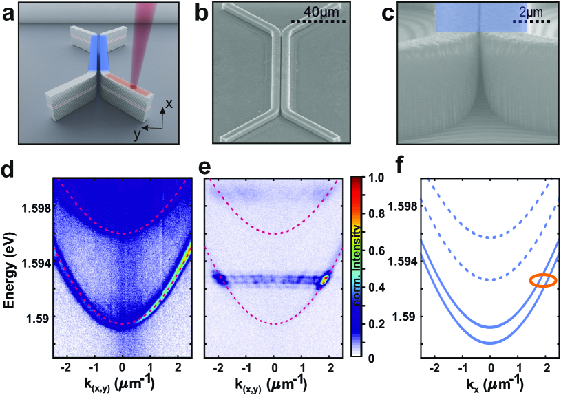
Fig. 1(a) shows a sketch of the intended structure, highlighting an excitation scheme (red), the incoupler region (orange) and the propagation direction along the coupling area (blue) . A scanning electron microscopy image of the full device as well as a zoomed view of the coupling region, stressing the fabrication-induced narrow gap between the structures, are presented in Figs. 1(b) and (c), respectively. The incoupler, which is angled 45∘ to the propagation direction (see Fig. 1(a)), has a width of m and a length of m. Figs. 1 (d) and (e) depict the energy dispersion of the ground state along the incoupler region in the linear regime and above threshold, respectively. The calculated dispersion along the coupler is shown in Fig. 1(f).
The experiments have been carried out with two photoluminescence setups, the first capable of both Fourier- and real space emission detection while the second one was used for streak camera measurements. Excitation was provided using a tuneable Ti:Sa-Lasers with 10 ps and 2 ps pulse lengths set at the wavelength of a high energetic Bragg mode of the microcavity at each structure for efficient injection. The excitation was mechanically chopped with a ratio of 1:12 to prevent sample heating. Additionally, a tomography technique using motorized lenses was implemented to allow for energy selective imaging. The pump spot was focused via a microscope objective with NA = 0.42 to a diameter of m.
As an example, we show the characterization of a single waveguide with an excitation spot located at the center of the incoupler. The dispersion depicted in Fig. 1(d) was measured parallel to the incoupler at a low excitation density of 0.1 mW and features photoluminescence from two modes, characteristic for the waveguide’s one dimensional confinement. These modes have been fitted with an approach from Ref. Tartakovskii.1998 . This allows to extract a detuning of -20 meV with an exciton energy of 1.609 eV, corresponding to photonic and excitonic fractions of 90.6% and 9.4%, respectively.
To move on, an investigation of the non-linear regime in this structure, is represented in Fig. 1(e), showing polaritons above threshold being expelled from the small laser pump spot Wertz2010 at a wave vector kx 1.9 . A detailed analysis of the emission intensity and energy as a function of the excitation power revealing a lasing threshold behavior and a continuous blueshift of 4 meV is presented in the supplementary materials, confirming polariton interaction effectsCiuti.1998 .
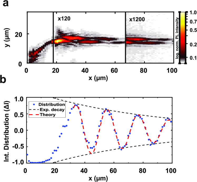
Let us now report on the main subject of the work, namely the oscillations in co-directional couplers. To this end, Fig. 2 (a) depicts a logarithmic color-coded real space image of the energy-resolved photoluminescence from two adjacent waveguides at an injection power of 1 mW, corresponding to the propagating condensate regime for eV. The gap between the two waveguides is 200 nm wide and the coupling area is m long. The emission from the region of the excitation spot (on the bottom left incoupler) is attenuated by a neutral density filter, while the far propagating condensate is amplified to compensate for its disspative nature. A clear oscillation pattern is observed upon propagation of the condensate into the coupling region of the two coupled waveguides. In panel (b), a quantitative analysis of the oscillation by plotting the intensity distribution between the two waveguides, where and denote the intensities in the top, bottom and both waveguides is presented. Therefore, corresponds to an equal distribution of the population. Due to continuous polariton decay, we observe an exponential spatial decay of the distribution characterized by a decay constant of . From this distribution a spatial oscillation period of can be extracted.
The governing physics behind the observed oscillation dynamics can be understood within a slowly- varying amplitude approach for the modes of the coupled waveguides. Since the excitation occurs above condensation threshold, the ballistic polaritons have a well-defined frequency. Thus we focus on spatial dynamics along the propagation axis considering a monochromatic case. In the low-intensity limit the dynamics can be modelled via two coupled equations for amplitudes in the coupled waveguides
| (1) |
| (2) |
where is the complex coupling constant which is governed by the width and depth of the gap between the coupled waveguides. The complex wavevector characterizes the propagation and damping of guided modes in separated waveguides (in the following .
In order to find the super-modes of the coupler we look for a solution of Eqs. (1) and (2) in the form . By diagonalizing the system one finds two eigenmodes, namely symmetric and antisymmetric one, with the propagation constants and , respectively. It is worth mentioning that, due to the imaginary parts of the coupling constants, the damping rates of these two modes are different. More precisely, the antisymmetric mode has smaller propagation losses.
If only one waveguide is excited (with an amplitude ), the analytical solution for the mode dynamics can be easily found as
| (3) | ||||
| (4) | ||||
From the analytical solution (3,4) it is easy to derive a simple expression for the intensity distribution in the coupler
| (5) |
This solution has a form of damped oscillations where polaritons transfer between the two channels with a spatial period and a damping coefficient given by the imaginary part of the coupling constant [see Fig. 2 (b)] . The physical origin of the oscillations is the beating of two (symmetric and antisymmetric) eigenmodes.
It is worth mentioning, that, due to the etching of the Bragg mirror between two channels, the effect of local losses becomes comparable with the polariton tunnelling dynamics and thus the imaginary part of the coupling cannot be neglected. For a non-zero imaginary part , the symmetric mode decays faster and at propagation distances of the order of it becomes much less intensive than the antisymmetric mode. This suppresses the mode beating at large propagation distances.
To underpin this rather qualitative analysis with a more thorough theoretical study, we performed numerical calculations in the frame of the mean-field model for 2D intracavity photons coupled strongly to the quantum well excitons Amo09 ; Carusotto2013 . This is a widely accepted approach for exciton-polariton dynamics in microcavities where the required waveguiding geometry can be accounted by inducing an appropriate potential for photons. Neglecting polarization effects one obtains two coupled Schrödinger equations for the photonic field and coherent excitons given as
| (6) |
| (7) |
The complex amplitudes are obtained through a standard averaging procedure of the related creation or annihilation operators. and denote the cavity photon damping and dephasing rate of excitons, respectively. We note that, for cryogenic sample temperatures, the excitonic dephasing time can be comparable with the life-time of intracavity photons. Thus, without loss of generality, they are assumed to be equal meV. The effective photon mass in the planar region is given by where is the free electron mass. The effective mass of excitons is . is the Rabi frequency which defines the Rabi splitting . The photon - exciton detuning is given by the parameter where is the cavity resonance frequency and is the excitonic resonance.
The external photonic potential defines the waveguide geometry induced by etching of the Bragg mirror. An appropriate profile of the potential was chosen after a thorough fitting of the dispersion relation of the guided modes known from the experiment [see Figs. 1(d) and (e)]. The real part of the best-fitted profile was found to be a super-Gauss with the depth and the width of . We also estimated the potential depth in the gap between two waveguides in the coupler region to be [see the calculated dispersion relation in Fig. 1(f)]. The imaginary part of the potential accounts for additional damping induced by etching of the Bragg mirror and was approximated by the expression with and .
Since we are interested in the propagation dynamics of polaritons with a well-defined frequency it is sufficient to consider the case of coherent excitation by a pump beam with a frequency and with a momentum such that the parameter describes the detuning of the pump frequency from the excitonic resonance.
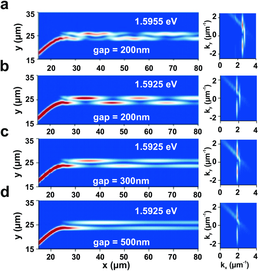
Figs. 3(a) and (b) show examples of oscillation dynamics for two slightly different frequencies of the wave-packets. These oscillations are governed by interference of the symmetric and the antisymmetric modes of the coupler, which is clearly visible in the two-dimensional spectrum, shown in the insets to Figs. 3. The insets in each panel represent the momentum space distribution of the propagating polaritons. The substantial difference in the period of spatial oscillations can be explained by a non-equidistant momentum splitting between the mentioned above symmetric and antisymmetric modes within the dispersion relation of the coupler [see Fig. 1(f)].
Further examples in Figs. 3(c)-(d) show propagation dynamics in which the coupling strength is continuously weakened due to decreased wavefunction overlap via increased gap width. A clear change in the oscillation pattern is observed.
Note that, due to pronounced dissipative effects within the gap between waveguides, the antisymmetric mode, which has the lowest overlap with the gap region, dominates the spectrum for larger gaps and, as a result, oscillations disappear [see Fig. 3(d)].
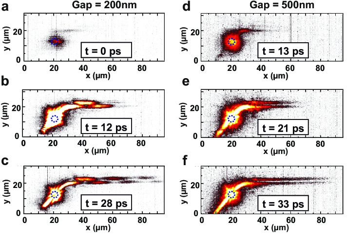
Now, in order to demonstrate the polariton dynamics in the co-directional coupler devices experimentally, we have performed energy- and time-resolved streak camera measurements using two devices with gap sizes of 200 nm and 500 nm. Using a streak camera with an overall time resolution of 10 ps, the PL has been measured up to 150 ps after the laser beam excites the structure at t=0. However, due to the fast dynamics of polaritons in this sample, the polariton propagation is only shown up to ∼30 ps. The respective intensity patterns are plotted in Figs. 4 (a)-(c) and (d)-(f).
In Fig. 4 (a) at t=0 ps, we observe the laser excitation spot on the lower left input coupler from where polaritons are repulsively expelled into the coupling region. At t=12 ps, the polaritons have finished the first full oscillation in the upper waveguide and are back in the lower one. Finally, after approximately 30 ps, the polariton population has dissipated after a propagation length of 100 m, underlining the excellent quality of the patterned microcavity structure. The oscillation period is in excellent agreement with the theoretical model. Figs. 4 (d)-(f) shows the temporal evolution in a system with a much larger gap of 500 nm. In this case, while there is some evanescent coupling to the upper waveguide, no pronounced oscillatory behavior is observed, again in excellent agreement with the theory presented in Fig. 3.
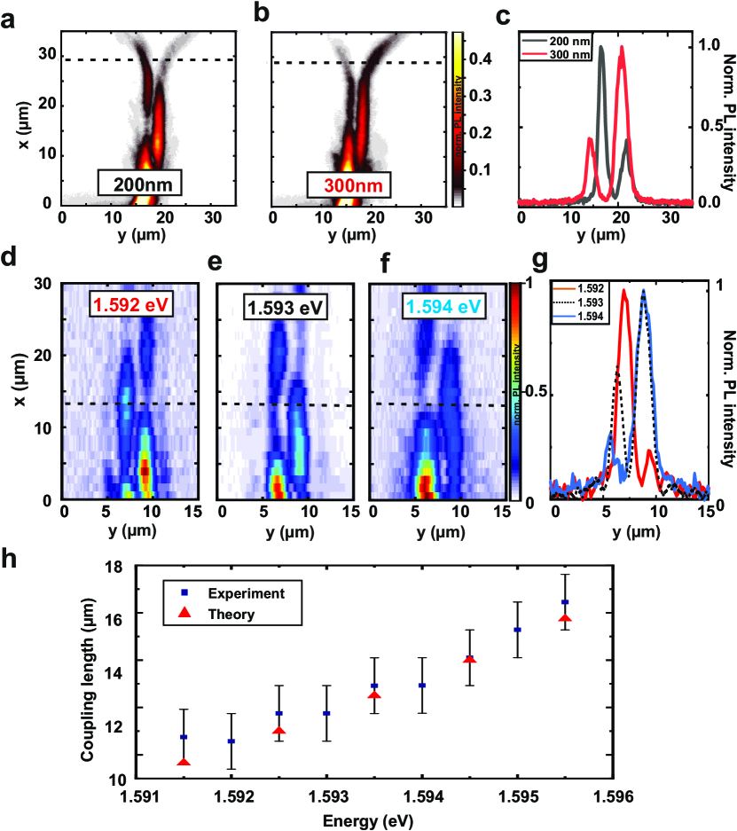
From the experiments as well as from the theoretical model, we can infer that a variation in the coupling strength ultimately allows for a change of the oscillation period. This can now be used to choose the output-port of the polariton flow due to a specifically tailored channel length and etch depth. Fig. 5 shows the results of the experiments. We have used similar couplers with 200 nm and 300 nm gap size respectively, but with a reduced coupler region length of 20 m. While (a) shows the polariton flow leaving predominantly through the left outcoupler, the larger gap (weaker coupling and larger oscillation length) in (b) shows predominant coupling to the right arm. In (c) the normalized line-profiles are plotted for Figs. 5(a,b) at m. A clear change in output is visible and can be characterized by the ratio of the integrated routed intensities. These were extracted as 1.9 and 3.1 for Figs. 5(a,b), respectively.
Another way of changing the output port is by changing the energy of the polariton condensate. The emissions of a condensate for three different energies ranging from 1.592-1.594 eV are shown in Figs. 5(d-f). Changing the condensate propagation energy by 2 meV, a change of the intensity from left to right can be observed. This shift is underlined by the line profiles in Fig. 5(g). The detailed change of coupling lengths and the numerically calculated values for Figs. 5(d-f) are depicted in the Fig. 5(h).
Therefore we have shown that this device configuration allows co-directional routing to a predetermined exit-port via a Josephson-like oscillation effect in real space by engineering the period and coupling length.
In conclusion, we have demonstrated the possibility for passive polariton routing, which is easily scalable and integratable to large polariton based logic networks. We evidenced this by a precise control of the lithographically engineered photonic landscape, which allows for the observation of these oscillations in real space between polaritonic waveguides. Such detailed tailoring of the flow of quantum fluids of light paves the way to harness their non-linearity in next generation photonics. Furthermore, the basic understanding of the coupling of polariton waveguides Klaas2019 ; Rozas2020 is the necessary foundation for larger coupled waveguide arrays, comparable to those that have been implemented in Si-photonics for the demonstration of transport in a topological defect waveguide Redondo2016 or Floquet waveguides for the study of topologically protected bound states in photonic parity-time symmetric crystalsWeimann2017 . In this respect, our work opens a new route, to use polariton waveguides for polariton logic as well as for topological devices involving nonlinearity, gain, interactions and coherence, inherent to the polariton system.
Acknowledgements.
The Würzburg and Jena group acknowledge financial support within the DFG projects SCHN1376/3-1, PE 523/18-1 and KL3124/2-1 . The Würzburg group is grateful for support from the state of Bavaria and within the Würzburg-Dresden Cluster of Excellence ct.qmat. S.H. also acknowledges support by the EPSRC “Hybrid Polaritonics” grant (EP/ M025330/1). The Würzburg group wants to thank Hugo Flayac for inspiring discussions in the early stage of this work.The Madrid group acknowledges financial support of the Spanish MINECO Grant MAT2017-83722-R. E.R. acknowledges financial support from a Spanish FPI Scholarship No. BES-2015-074708. I.A.Shelykh acknowledges financial support of Icelandic Science Foundation (project “Hybrid polaritonics”). I.A.Shelykh and A.Yulin acknowledge Ministry of Science and Higher Education of the Russian Federation (Megagrant number 14.Y26.31.0015).
References
- (1) D.A.B. Miller, Nat. Photonics 4, 3 (2010).
- (2) C. Weisbuch, M. Nishioka, A. Ishikawa, and Y. Arakawa, Phys. Rev. Lett. 69, 3314 (1992).
- (3) J. Kasprzak, M. Richard, S. Kundermann, A. Baas, P. Jeambrun, J. M. J. Keeling, F. M. Marchetti, M. H. Szymanska, R. Andre, J. L. Staehli, V. Savona, P. B. Littlewood, B. Deveaud, and L. S. Dang, Nature 443, 409 (2006).
- (4) A. Imamoglu, R. J. Ram, S. Pau, and Y. Yamamoto, Phys. Rev. A 53, 4250 (1996).
- (5) I. Carusotto and C. Ciuti, Rev. Mod. Phys. 85, 299 (2013).
- (6) A. Amo, J. Lefrere, S. Pigeon, C. Adrados, C. Ciuti, I. Carusotto, R. Houdre, E. Giacobino, and A. Bramati, Nat. Phys. 5, 805 (2009).
- (7) B. Nelsen, G. Liu, M. Steger, D.W. Snoke, R. Balili, K. West, and L. Pfeiffer, Phys. Rev. X 3, 041015 (2013).
- (8) E. Wertz, A. Amo, D.D. Solnyshkov, L. Ferrier, T.C.H. Liew, D. Sanvitto, P. Senellart, I. Sagnes, A. Lemaître, A. V. Kavokin, G. Malpuech, and J. Bloch, Phys. Rev. Lett. 109, 216404 (2012).
- (9) M. Vladimirova, S. Cronenberger, D. Scalbert, K. V. Kavokin, A. Miard, A. Lemaître, J. Bloch, D. Solnyshkov, G. Malpuech, and A. V. Kavokin, Phys. Rev. B 82, 075301 (2010).
- (10) G. Muñoz-Matutano, A. Wood, M. Johnsson, X. Vidal, B. Q. Baragiola, A. Reinhard, A. Lemaître, J. Bloch, A. Amo, G. Nogues, B. Besga, M. Richard and T. Volz, Nat. Mater. 18, 213–218 (2019).
- (11) A. Delteil, T. Fink, A. Schade, S. Höfling, C. Schneider and A. Imamoglu, Nat. Mater. 18, 219–222 (2019).
- (12) D. Sanvitto, and S. Kena-Cohen, Nat. Mater. 15, 1061 (2016).
- (13) T. C. H. Liew, A. V. Kavokin, and I. A. Shelykh, Phys. Rev. Lett. 101, 016402 (2008).
- (14) A. Amo, T. C. H. Liew, C. Adrados, R. Houdré, E. Giacobino, A. V. Kavokin, and A. Bramati, Nat. Photonics 4, 361 (2010).
- (15) C. Anton, T. C. H. Liew, G. Tosi, M. D. Martń, T. Gao, Z. Hatzopoulos, P. S. Eldridge, P. G. Savvidis, and L. Viña, Appl. Phys. Lett., 101, 261116 (2012)
- (16) T. Gao, P. S. Eldridge, T. C. H. Liew, S. I. Tsintzos, G. Stavrinidis, G. Deligeorgis, Z. Hatzopoulos, and P. G. Savvidis, Phys. Rev. B 85, 235102 (2012).
- (17) C. Anton, T. C. H. Liew, J. Cuadra, M. D. Martin, P. S. Eldridge, Z. Hatzopoulos, G. Stavrinidis, P. G. Savvidis, and L. Viña, Phys. Rev. B 88, 245307 (2013)
- (18) D. Ballarini, M. De Giorgi, E. Cancellieri, R. Houdr,́ E. Giacobino, R. Cingolani, A. Bramati, G. Gigli, and D. Sanvitto, Nat. Commun. 4, 1778 (2013).
- (19) H. S. Nguyen, D. Vishnevsky, C. Sturm, D. Tanese, D. Solnyshkov, E. Galopin, A. Lemaître, I. Sagnes, A. Amo, G. Malpuech, and J. Bloch, Phys. Rev. Lett. 110, 236601 (2013).
- (20) H. Suchomel, S. Brodbeck, T. C. H. Liew, M. Amthor, M. Klaas, S. Klembt, M. Kamp, S. Höfling and C. Schneider, Sci. Rep. 7, 5114 (2017).
- (21) K. Winkler, H. Flayac, S. Klembt, A. Schade, D. Nevinskiy, M. Kamp, C. Schneider, and S. Höfling, Phys. Rev. B 95, 201302(R) (2017).
- (22) R. Su, J. Wang, J. Zhao, J. Xing, W. Zhao, C. Diederichs, T. C. H. Liew and Qihua Xiong, Sci. Adv. 4, eaau0244 (2018).
- (23) A. V. Zasedatelev, A. V. Baranikov, D. Urbonas, F. Scafirimuto, U. Scherf, T. Stöferle, R. F. Mahrt, P. G. Lagoudakis, Nat. Photonics 13, 378–383 (2019).
- (24) H. Deng, G. Weihs, D. Snoke, J. Bloch, and Y. Yamamoto, PNAS 100, 15318 (2003).
- (25) H. Flayac, and I. G. Savenko, Appl. Phys. Lett. 103, 201105 (2013).
- (26) F. Marsault, H.S. Nguyen, D. Tanese, A. Lemaître, E. Galopin, I. Sagnes, A. Amo, and J. Bloch, Appl. Phys. Lett. 107, 201115 (2015).
- (27) B. Josephson, Phys. Lett. 7, 251 (1962).
- (28) P. W. Anderson, Rev. Mod. Phys. 38, 298 (1966).
- (29) F. S. Cataliotti, S. Burger, C. Fort, P. Maddaloni, F. Minardi, A. Trombettoni, A. Smerzi, and M. Inguscio, Science 293, 843 (2001).
- (30) M. Albiez, R. Gati, J. Foelling, S. Hunsmann, M. Cristiani, und M. K. Oberthaler, Phys. Rev. Lett. 95, 010402 (2005).
- (31) R. Gati, M. Albiez, J. Foelling, B. Hemmerling. und M. Oberthaler, Appl. Phys. B 82, 207 (2006).
- (32) R. Gati, und M. K. Oberthaler, J. Phys. B 40, R61 (2007).
- (33) S. Levy, E. Lahoud, I. Shomroni, und J. Steinhauer, Nature 449, 579 (2007).
- (34) A. Smerzi, S. Fantoni, S. Giovanazzi, and S. R. Shenoy, Phys. Rev. Lett 79, 4950 (1997).
- (35) A. J. Leggett, Rev. Mod. Phys. 73, 307 (2001).
- (36) K. G. Lagoudakis, B. Pietka, M. Wouters, R. André, and B. Deveaud-Plédran, Phys. Rev. Lett. 105, 120403 (2010).
- (37) M. Abbarchi, A. Amo, V. G. Sala, D. D. Solnyshkov, H. Flayac, L. Ferrier, I. Sagnes, E. Galopin, A. Lemaître, G. Malpuech, and J. Bloch, Nat. Phys. 9, 275 (2013).
- (38) A. F. Adiyatullin, M. D. Anderson, H. Flayac, M. T. Portella-Oberli, F. Jabeen, C. Ouellet-Plamondon, G. C. Sallen and B. Deveaud, Nature Commun. 8, 1329 (2017).
- (39) C. Schneider, K. Winkler, M. D. Fraser, M. Kamp, Y. Yamamoto, E. A. Ostrovskaya and S. Höfling, Rep. Prog. Phys. 80, 1 (2016).
- (40) A. I. Tartakovskii and V. D. Kulakovskii and A. Forchel and J. P. Reithmaier, Phys. Rev. B 57, R6807 (1998).
- (41) E. Wertz, L. Ferrier, D. D. Solnyshkov, R. Johne, D. Sanvitto, A. Lemaître, I. Sagnes, R. Grousson, A. V. Kavokin, P. Senellart, G. Malpuech, and J. Bloch, Nat. Phys. 6, 860–864 (2010).
- (42) C. Ciuti, V. Savona, C. Piermarocchi, A. Quattropani, and P. Schwendimann, Phys. Rev. B 58, 7926 (1998).
- (43) M. Klaas, J. Beierlein, E. Rozas, S. Klembt, H. Suchomel, T. H. Harder, K. Winkler, M. Emmerling, H. Flayac, M.D. Martín, L. Viña, S. Höfling, and C. Schneider Appl. Phys. Lett. 114, 061102 (2019)
- (44) E. Rozas, J. Beierlein, A.Yulin, M. Klaas, H. Suchomel, O. Egorov, I.A. Shelykh, U. Peschel, C. Schneider, S. Klembt, S. Höfling, M.D. Martín, and L. Viña, Adv. Optical Mater. (2020) DOI: 10.1002/adom.202000650.
- (45) A. Blanco-Redondo, I. Andonegui, M. J. Collins, Gal Harari, Y. Lumer, M. C. Rechtsman, B. J. Eggleton, and M. Segev Phys. Rev. Lett. 116, 163901 (2016).
- (46) S. Weimann, M. Kremer, Y. Plotnik, Y. Lumer, S. Nolte, K. G. Makris, M. Segev, M. C. Rechtsman, and A. Szameit Nat. Mater. 16, 433–438 (2017).