∎
Thermo-poro-elastic behaviour of a transversely isotropic shale: Thermal expansion and pressurization
Abstract
The Callovo-Oxfordian (COx) claystone is considered as a candidate host rock for a deep geological radioactive waste repository in France. Due to the exothermic waste packages, the rock is expected to be submitted to temperatures up to 90 ∘C. The temperature rise induces deformations of the host rock, together with an increase in pore pressures, involving complex thermo-hydro-mechanical (THM) couplings. This study aims to better characterize the THM response of the COx claystone to temperature changes in the laboratory. To this end, claystone specimens were tested in a temperature controlled, high pressure isotropic compression cell, under stress conditions close to the in-situ ones. Thermal loads were applied on the specimens along different heating and cooling paths. A temperature corrected strain gage system provided precise measurements of the anisotropic strain response of the specimens. Drained and undrained thermal expansion coefficients in both transversely isotropic directions were determined. The measurement of pore pressure changes in undrained condition yielded the thermal pressurization coefficient. All parameters were analysed for their compatibility within the thermo-poro-elastic framework, and their stress and temperature dependency was identified.
Keywords:
Thermo-poro-elasticity Transverse isotropy Thermal pressurization ClaystoneList of Symbols
Note that the matrix notation is used throughout this work.
| Strain vector containing the 6 independent components of the second rank strain tensor | |
| Volumetric strain | |
| Drained compliance tensor in matrix format | |
| Stress vector containing the 6 independent components of the second rank stress tensor | |
| Isotropic confining stress | |
| Terzaghi isotropic effective stress | |
| Biot’s coefficient for -th direction | |
| Pore fluid pressure | |
| Temperature | |
| Linear drained thermal expansion coefficient in the -th direction | |
| Volumetric drained thermal expansion coefficient | |
| Biot’s linear pore pressure loading modulus in the -th direction | |
| Biot’s volumetric pore pressure loading modulus | |
| Drained bulk modulus | |
| Unjacketed bulk modulus | |
| Linear undrained thermal expansion coefficient in the -th direction | |
| Volumetric undrained thermal expansion coefficient | |
| Thermal pressurization coefficient | |
| Volumetric thermal expansion coefficient of the pore fluid | |
| Volumetric thermal expansion coefficient of the pore space | |
| Porosity | |
| Unjacketed pore modulus | |
| Bulk modulus of the pore fluid | |
| Measured thermal pressurization coefficient | |
| Corrected thermal pressurization coefficient | |
| Thermal pressurization coefficient of the drainage system | |
| Volume of the drainage system | |
| Compressibility of the drainage system | |
| Compressibility of the pore fluid | |
| Specimen volume | |
| Measured volumetric undrained thermal expansion coefficient | |
| Corrected volumetric undrained thermal expansion coefficient | |
| Elasto-plastic drained thermal expansion coefficient in the -th direction | |
| Inelastic drained thermal expansion coefficient in the -th direction | |
| Ratio between pore water and bulk water thermal expansion coefficients | |
| Model parameter for the temperature dependency of | |
| Wet density | |
| Dry density | |
| Water content | |
| Saturation degree | |
| Suction | |
| Hydration swelling |
1 Introduction
The identification of thermo-poro-elastic parameters of host rocks for deep geological radioactive waste disposal is of great importance to predict the effect of the heat generated from exothermic waste packages. The microtunnels, in which the exothermic waste packages will be placed, are designed with sufficient distance to each other, as to prevent temperatures larger than 90 ∘C in the host rock. Various in-situ and laboratory studies have been carried out among others on the COx claystone, as well as on the Opalinus claystone, a possible host rock in Switzerland with comparable characteristics.
In undrained conditions, a rise of temperature in claystone does not only generate thermal strains, but can also induce an increase in pore pressure, called thermal pressurization (Ghabezloo and Sulem, 2009). This phenomenon has been measured in-situ, during the TER test in COx claystone in the Bure underground laboratory and during the HE-D test in Opalinus clay in the Mont Terri rock laboratory (see for instance Gens et al., 2007 and Seyedi et al., 2017). Also in the laboratory, thermal pressurization, characterized through the thermal pressurization coefficient, has been investigated on COx samples (Mohajerani et al., 2012; Zhang et al., 2017). These authors indicated, that the thermal pressurization is due to different coupled THM properties, which can vary with stress and/or temperature. Hence also the thermal pressurization coefficient can be dependent on both temperature and stress conditions.
In particular, thermal pressurization of claystones is governed by the thermal expansion and elastic properties of both rock matrix and pore fluid. Gens et al. (2007) concluded in their numerical sensitivity analysis of in-situ tests, that the most important coupling occurred between thermal and hydraulic behaviour, when the relatively high thermal expansion coefficient of water generates pore pressure. This is followed by the coupling between hydraulic and mechanical properties, as the increasing pore pressure causes deformation of the rock matrix. Here one also has to take into account the anisotropic nature of stiff clays. Considering the importance of the thermal expansion properties of solid and fluid phases, these authors found that a wide range of values from laboratory experiments exist in this regard.
Different studies aimed therefore to identify separately these THM characteristics and back-calculate the thermal pressurization coefficient, using a thermo-poro-elasticity framework (Ghabezloo and Sulem, 2009): In drained heating tests, the thermal expansion properties of the rock matrix were investigated. Monfared et al. (2011) observed the thermal volume changes of Opalinus clay, where under heating up to 65 ∘C the specimens expanded, prior to exhibiting contraction at higher temperatures. This contraction was of plastic nature, evidenced after a subsequent cooling and re-heating cycle. Belmokhtar et al. (2017a) made similar observations above 48 ∘C on the COx claystone. The temperature, at which plastic contraction occurred, was suspected to be close to the maximum temperature to which the material was previously exposed to during its geological history (around 50 ∘C for COx claystone according to Blaise et al., 2014). Such thermoplastic behaviour has also been observed on clay, for which thermal expansion properties can depend on its degree of consolidation. Various clays exhibit a thermoelastic expansion when in overconsolidated state, and thermoplastic contraction in normally consolidated state (e.g. Baldi et al., 1988; Sultan et al., 2002 on Boom clay, Abuel-Naga et al., 2007 on Bangkok clay).
Moreover, peculiar features of the thermal expansion coefficient of the pore water in clayey geomaterials have been indicated. For instance, Monfared et al. (2011) presented some data on the undrained thermal behaviour of Opalinus clay, that could only be reproduced by adopting an anomalously high thermal expansion coefficient of the pore fluid. Similar observations have been previously made by Baldi et al. (1988) on low porosity clays. Indeed, Derjaguin et al. (1992) and Xu et al. (2009) reported this anomaly on water contained in small pores of silica gel and silica glasses, respectively. This phenomenon has hitherto not been observed on the COx claystone.
In our companion paper (Braun et al., 2020a), we identified the hydro-mechanical properties of the COx claystone in isothermal conditions. Laboratory experiments were conducted in drained and undrained state, applying total stress changes and hydraulic loading. This provided elastic coefficients, which constitute the transversely isotropic stiffness matrix and the transversely isotropic Biot coefficients of the material. These coefficients, taking into account their change with Terzaghi isotropic effective stress, were used in the present work for the back-analysis of the thermal pressurization coefficient.
The experimental study presented in this work was carried out to further characterize the thermal behaviour of the COx claystone. Complementing the data provided by Mohajerani et al. (2012), Mohajerani et al. (2014) and Belmokhtar et al. (2017a), we aim for obtaining a complete set of transversely isotropic THM parameters, able to describe strains and pore pressure changes occurring under thermal loads. COx samples were tested along various heating and cooling paths under constant total stress. This was done in an isotropic high pressure loading cell (Tang et al., 2008), improved by a temperature corrected strain gage system. The device permitted precise deformation measurements on the specimens, allowing the determination of drained and undrained thermal expansion coefficients, as well as of the thermal pressurization coefficient.
2 Thermo-Poro-Elastic Framework
The COx claystone is transversely isotropic, with lower stiffness and higher thermal expansion coefficients perpendicular to the bedding plane (Chiarelli, 2000; Escoffier, 2002; Andra, 2005; Mohajerani et al., 2012; Zhang et al., 2012; Belmokhtar et al., 2017a, b).
The thermal properties and THM couplings in the COx claystone are analysed within a thermo-poro-elastic constitutive framework, reviewed amongst others by Biot and Willis (1957), Palciauskas and Domenico (1982) and Coussy (2004). In this work, we use the matrix notation, with stress and strain vectors and , containing the 6 independent components of their corresponding second rank tensors. Following the formulation of Cheng (1997) for a transversely isotropic material, we express a change of strains with respect to a change of stresses , pore fluid pressure and temperature as a sum of partial derivatives:
| (1) |
where is the transversely isotropic compliance matrix, a vector of transversely isotropic Biot’s coeffients, described by Cheng (1997), and a vector of linear drained thermal expansion coefficients. The spatial orientations of the stress/strain tensor and the thermal expansion properties are depicted on a elementary volume in Fig. 1.
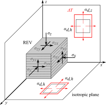
It has to be noted that in this thermo-poro-elastic framework, we neglect possible reversible sorption-desorption phenomena, which have been widely discussed on certain geomaterials such as clay or coal (e.g. Martin, 1962; Liu et al., 2018). Here we do not consider a mass exchange between water adsorbed within the solid phase and bulk water in the pore space. The vector of thermal expansion consists of the two linear drained thermal expansion coefficients perpendicular () and parallel () to the bedding orientation:
| (2) |
The volumetric drained thermal expansion coefficient is calculated with . The volumetric strain response of the porous medium due to pore pressure change under constant total stress and temperature is characterized by the Biot modulus :
| (3) |
where is the volumetric strain, the isotropic drained bulk modulus and unjacketed bulk modulus (Brown and Korringa, 1975). The modulus relates volumetric strains to stress changes, when equal increments of isotropic stress and pore pressure are applied to a specimen. The Biot modulus can also be expressed in terms of components in different anisotropy directions , by using:
| (4) |
A relationship between the volumetric modulus and the linear moduli is found by . Undrained conditions are defined for a constant pore fluid mass in the porous medium under loadings. Under this condition, one obtains the following changes in strains under constant stresses:
| (5) |
where denotes the two linear undrained thermal expansion coefficients perpendicular () and parallel () to the bedding orientation:
| (6) |
The volumetric undrained thermal expansion coefficient can be calculated according to . The pore pressure changes in undrained conditions under constant total stress are described by:
| (7) |
where represents the thermal pressurization coefficient (Ghabezloo et al., 2009b). According to Ghabezloo et al. (2009b) and by using Eq. (3), can be expressed as:
| (8) |
where and are the bulk thermal expansion coefficients of the pore fluid of the pore space, respectively. denotes the unjacketed pore modulus (Brown and Korringa, 1975), the porosity, the Biot’s moduls and the fluid bulk modulus.
Eq. (8) shows that the thermal pressurization is mainly caused by the difference between the bulk thermal expansion coefficients of the fluid and that of the pore space . In geomechanical applications, when the material is micro-homogeneous, we can assume that is equal to the drained volumetric thermal expansion coefficient . In the same manner, one can take the bulk modulus of the pore space equal to the unjacketed bulk modulus .
Comparing Eq. (1) with (5) and (7), one obtains the following relationship:
| (9) |
This can be simplified in terms of the bulk volume change (Ghabezloo et al., 2009b) as follows:
| (10) |
We can evaluate , and in undrained heating tests, whereas and are determined in drained heating. The moduli and can then be calculated using Eq. (9). Alternatively, if are also measured, the parameter set (, , and ) is overdetermined, and the values can be checked for their consistency (i.e. for each unknown we can compare its measured value with the one back-calculated from the other unknowns, see also Menke, 1989; Hart and Wang, 1995; Braun et al., 2019).
3 Materials and Methods
3.1 The Callovo-Oxfordian Claystone
Samples of the COx claystone have been retrieved at Bure, in the east of France, from an underground research laboratory (URL). This URL at about 490 m depth was established by the French national agency for radioactive waste management, Andra, to study the behaviour of the claystone during tunnel excavation and during the long term disposal of radioactive waste (Andra, 2005; Armand et al., 2017; Conil et al., 2018). At the URL level, the claystone has a clay content of around 42 , with an average porosity of 17.5 and an average water-content of 7.9 (Conil et al., 2018). The solid matrix comprises interstratified illite/smectite layers, illite, kaolinite and chlorite (Gaucher et al., 2004). Wileveau et al. (2007) determined a vertical and a minor horizontal total stress of around 12 MPa, a major horizontal stress of around 16 MPa and a pore pressure of about 4.9 MPa.
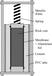
In this laboratory study, we investigated specimens trimmed from COx cores that were extracted at the URL from horizontal boreholes. To preserve the material in-situ state as best as possible, i.e. to avoid desaturation (Monfared et al., 2011; Ewy, 2015) and mechanical damage, cores were shipped and stored in T1 cells (Fig. 2), developed by Andra (Conil et al., 2018). T1 cells protect 80 mm diameter COx cores that are wrapped in aluminium foil and covered by latex membranes to prevent drying. A PVC tube is placed around the core and cement is poured between the membrane and the tube. Once hardened, the cement ensures radial confinement and shock protection. A mechanical spring is installed, which applies confining stress in axial direction.
After having removed the cores EST 53650 and EST 57185 from the T1 cells, the cores were sealed by a layer of paraffin wax. This layer provided drying protection and remained during the subsequent trimming process. Cylinders of 38 mm diameter were then drilled perpendicular to the bedding plane, using a air-cooled diamond coring bit. The cylinders were also protected by a paraffin layer, before being cut into 10 mm thick disks with a diamond string saw. The disks were enveloped by an aluminium-foil layer and covered by a mixture of 70 % paraffin wax and 30 % vaseline oil.
A petrophysical characterization, performed on cuttings of the cores directly after trimming and several months after storage, under the before-mentioned protection, is presented in Tab. 1. The specimen volume was determined by hydrostatic weighting in petroleum, while the dry density was obtained after oven drying at 105 ∘C for two days. A value for the solid density 2.69 g/cm3 was provided by Andra (Conil et al., 2018). The measurements of suction were carried out using a chilled mirror tensiometer (WP4, Decagon brand). We observed a relatively high degree of saturation, larger than 92.5 %, confirming a good sample preservation.
As indicated in Tab. 2, four specimens, ISO1 to ISO4, were tested in this study. Sample ISO1 was trimmed from core EST53650 and samples ISO2 to ISO4 from core EST57185.
| Core | ||||||
|---|---|---|---|---|---|---|
| EST | 2.37 | 2.22 | 17.9 | 7.5 | 92.5 | 24.2 |
| 53650 | (0.00) | (0.01) | (0.2) | (0.1) | (0.8) | (2.1) |
| EST | 2.38 | 2.21 | 18.2 | 7.9 | 95.3 | 17.4 |
| 57185 | (0.00) | (0.00) | (0.2) | (0.1) | (0.7) | (0.1) |
3.2 Isotropic cell
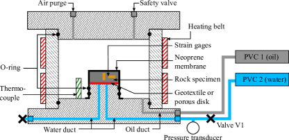
A high-pressure isotropic thermal compression cell, presented in Fig. 3 (Tang et al., 2008; Mohajerani et al., 2012; Belmokhtar et al., 2017a, b), was used to test specimens with 38 mm diameter and variable height, sealed within a neoprene membrane, in the centre of the cell. A silicone rubber electric heating belt is wrapped around the cell and coupled with a temperature sensor next to the specimen, giving control over the specimen temperature. The cell is filled with silicone oil, which can be set under a pressure of up to 40 MPa by a pressure volume controller (PVC 1, GDS brand). The neoprene membrane isolates the specimen from the silicone oil, so that the pressure of the pore fluid can be controlled independently. The pore pressure is applied from the bottom of the specimen through a porous disk connected to the pressure volume controller PVC 2. Local strains wereto the data of monitored using an axial and a radial strain gage (Kyowa brand) glued on the lateral surface of the specimen.
3.3 Correction of strain measurements
Measurements of strain gages can be altered by both temperature changes of the gage itself inside the cell and changes of the room temperature, affecting external cables. To account for these effects, a reference gage glued on a piece of steel 316L was placed next to the specimen. Knowing the thermal expansion coefficient of steel 316L, the thermally induced error strains, called apparent strains , can be measured simultaneously to the specimen strains and allow for real-time corrections. We found apparent strains in the same order of magnitude as the specimen strains, which emphasizes the necessity for correction.
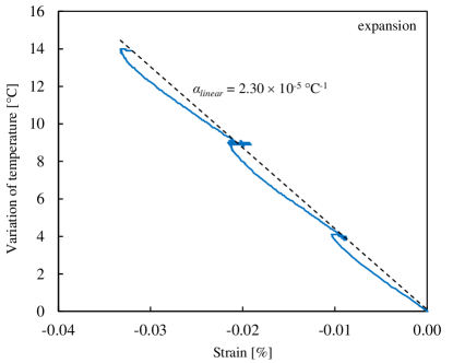
To verify the thermal strain measurements, a specimen of aluminium 2011 was equipped with a strain gage and tested in the cell. The reference gage was placed next to the specimen. The cell was heated in steps from 26 - 30 - 35 - 40 ∘C, while the strains of the aluminium specimen were recorded and corrected by . Fig. 4 shows the linear thermal expansion of the aluminium, with . This value corresponds to the value given from the manufacturer, validating a precise temperature correction.
Among the four tests carried out, a reference gage was installed in two tests (ISO3 and ISO4, see Tab. 2). In the two other tests (ISO1 and ISO2), the measured specimen strains were corrected a posteriori with a calculated , determined in function of cell temperature and room temperature.
3.4 Calibration of the effect of the drainage system
According to Wissa (1969); Bishop (1976) and Ghabezloo and Sulem (2009, 2010), undrained conditions imposed by a testing device might not always meet the requirement of a constant fluid mass inside the specimen. If there is some dead volume in the drainage system, such as ducts and porous disks, this volume changes due to the compressibility and thermal expansion of the drainage elements and of the fluid it contains. This allows fluid to either drain or be injected into the specimen, changing the fluid mass. The methods proposed to account for these effects require a precise calibration of the testing device. Using Eq. (11), presented by Braun et al. (2019) and adapted from Ghabezloo and Sulem (2010), the corrected thermal pressurization coefficient is obtained from the measured one :
| (11) |
where is the volume, the compressibility and the thermal pressurization coefficient of the drainage system. is the porosity and the total volume of the specimen. denotes the pore fluid compressibility. For sake of simplicity, we consider an ideal porous material with . The parameter of the testing device is determined by running a calibration test on a dummy metal specimen with zero porosity. Also, and of each specimen have to be measured before a test.
Similarly, we calculate a corrected undrained thermal expansion coefficient with the measured one , which requires knowledge of the Biot modulus (Ghabezloo and Sulem, 2010):
| (12) |
In this study, calibration was done by adopting mm3, GPa-1 and a temperature dependent (0.0056 + 0.208) , with in (see Braun et al., 2019, who used a similar device). For the fluid compressibility we used properties of bulk water, taking into account its temperature and pressure dependency (IAPWS-IF97, 2008).
3.5 Testing Procedure
Before installing a specimen in the testing device, the drainage ducts were emptied and dried by flushing with compressed air. Any contact of the claystone with water, before applying confining stress, could lead to swelling and risk specimen damage (Mohajerani et al., 2011; Menaceur et al., 2015; Ewy, 2015). Following the procedure illustrated in Fig. 5, the COx specimens were then mounted in the isotropic cell in their initial state at a constant ambient temperature. The specimens were consolidated without back pressure application under isotropic stress loading of 0.1 MPa/min.
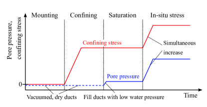
All specimens were brought to a confining pressure close to the in-situ effective stress (sample ISO1 to 10 MPa total stress and samples ISO2 - ISO4 to 8 MPa total stress, see Tab. 2) while monitoring deformations. Once the consolidation deformations stabilized, vacuum was applied to the drainage ducts to evacuate the remaining air. The dry ducts were then filled with synthetic pore water with a composition close to the in-situ one, provided by Andra, to saturate the specimens.
| Saturation | Test conditions | Average measured parameters | ||||||||||
| Core | Type | |||||||||||
| # | EST | [MPa] | [%] | [MPa] | [MPa] | [MPa/∘C] | [GPa] | |||||
| ISO1 | 57185 | 10 | 0.71 | three-stage | 14 | 4 | - | 0.53 | 4.82 | 2.30 | 0.19 | 2.32 |
| ISO2 | 53650 | 8 | 0.86 | two-stage | 12 | 4 | - | 0.60 | - | 2.03 | - | - |
| ISO3 | 53650 | 8 | 0.80 | two-stage | 12 | 4 | 0.18 | 0.30 | 4.63 | 1.86 | - | - |
| ISO4 | 53650 | 8 | 0.72 | three-stage | 14 | 4 | 0.22 | 0.51 | 4.93 | 1.99 | 0.20 | 2.49 |
| (1)only thermo-elastic values shown here | ||||||||||||
| (2)temperature dependent | ||||||||||||
The fluid pressure was chosen small enough in order to limit the change of effective stress and related poroelastic strains. Some swelling strains were observed that stabilized after about 5 days, with 0.71 % expansion for ISO1, 0.86 % expansion for ISO2, 0.80 % expansion for ISO3 and 0.72 % expansion for ISO4 (see Tab. 2). These values are comparable to the data of Belmokhtar et al. (2017b), who found 0.97 and 0.85 % for specimens saturated at 8 and 12 MPa effective stress, respectively.
After hydration, pore pressure and confining pressure were simultaneously increased under constant effective stress, until reaching pore pressure close to the in-situ one (4.0 MPa). This back pressure seemed sufficient for complete saturation, according to Rad and Clough (1984). They showed, that with the help of vacuum, a specimen at 90 % saturation can be fully re-saturated under around 150 kPa pore pressure. The key advantage is hereby the dissolution of air into water under pressure, according to Henry’s law. Also Favero et al. (2018) demonstrated that their specimens of Opalinus clay were completely saturated under 2 MPa pore pressure. Our samples ISO1 and ISO4 were brought to 14 MPa total stress, and samples ISO2 - ISO3 to 12 MPa total stress. Note that an additional increment of 2 MPa confining pressure was finally applied to ISO4, resulting in higher effective stress than during saturation.
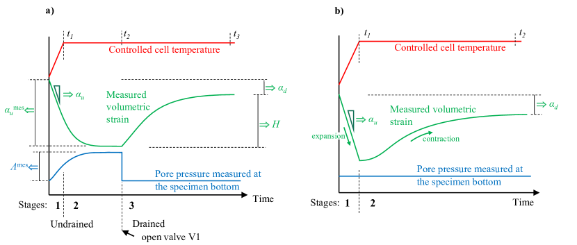
Two different step testing procedures, presented by Braun et al. (2019), were utilized to determine the THM parameters of the material. Samples ISO1 and ISO4 were tested following a three-stage protocol (Fig. 6a), that consists in rapidly increasing or decreasing the cell temperature in stage 1 until the time (rate of 10 ∘C/h), while the drainage system is kept closed. In this phase, one can measure (with its anisotropic components ) based on the temperature and strain measurements, using the initial tangent of . Initially, no pore pressure dissipation occurs, so that there is no need of correcting any effect of the drainage system (Braun et al., 2019). In stage 2 until , the temperature is kept constant until deformations and pore pressures stabilized. The corresponding pseudo-undrained conditions require the correction of the measured secant parameter and , according to Eqs. (11) and (12). In stage 3, the drainage system is opened, imposing the initial pore pressure. The pore pressure gradually comes back to its initial distribution through a transient phase governed by pore pressure diffusion, and a drained state is finally reached. At , after strain stabilization, the secant parameter can be determined. The change in pore pressure with respect to the change of strains during the third phase provides the secant modulus .
Samples ISO2 and ISO3 were tested under a two-stage procedure (Fig. 6b). The specimens are first rapidly heated or cooled in stage 1 until , under 10 ∘C/h, and then kept at constant temperature in stage 2. Even though the drainage system is always kept open, the temperature change is much faster than pore pressure diffusion, and one can measure the undrained tangent parameter . After reaching stable strains in a completely drained state at , the secant parameter can be measured. Note that in both procedures, for each measurement of the volumetric properties and , we obtain at the same time the corresponding linear components with respect to the two directions parallel and perpendicular to bedding, e.g. with and .
The isotropic total stress was always kept constant during the tests, and the pore pressure at the bottom of the specimen was kept constant by the PVC. Even though the pore pressure at the bottom is constant, the pore pressure distribution within the specimen changes during thermal loading due to thermal pressurization. However, at the end of the step tests after pore pressure dissipation, the specimen is in hydraulic equilibrium, resulting in a constant pore pressure distribution equal to the initial pore pressure. The stress conditions before and after the step test, when drained strains are measured, are identical. Drained thermal strain changes were therefore always evaluated under constant stresses. In the intermediate undrained phase however, the pore pressure varies according to (Eq. (7)). Consequently, this changes the effective stress depending on the increment of temperature applied in one step and the thermal pressurization coefficient. If the material properties are stress dependent, this change of effective stress has to be considered in the analysis of undrained parameters. Also, a temperature dependency of the observed properties has to be taken into account, if the temperature increments are large.
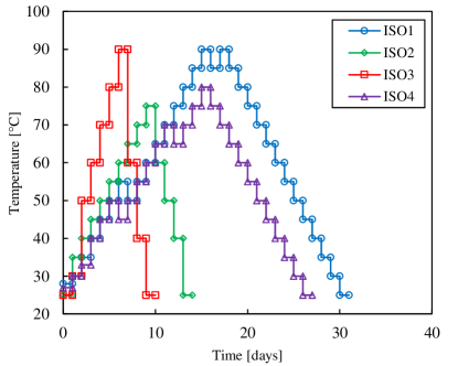
The temperature, at which the measured parameters are presented in the following, was chosen as the mean between initial and final temperatures during each step test. In a series of subsequent temperature step tests, the specimens were heated until 90 ∘C (ISO1, ISO3), 80 ∘C (ISO4) and 75 ∘C (ISO2), and then cooled back, as presented in Fig. 7. The utilized testing procedures, as well as stress and pore pressure conditions and measured material parameters are summarized in Tab. 2 (note that the axial strain gage on sample ISO2 failed after saturation, so that only radial strains could be recorded during this test).
4 Experimental results
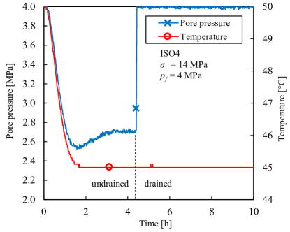
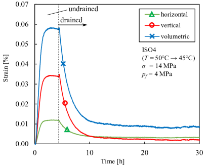
The data of a typical three-stage thermal test, run on specimen ISO4 between 50 to 45 ∘C, are presented in Fig. 8 and 9 in terms of pore pressure and strain changes, respectively. Here, the specimen was cooled and the temperature decrease resulted in a pore pressure decrease (thermal de-pressurization during cooling, equivalent to thermal pressurization during heating). The target temperature was reached after about 1.5 h and then kept constant. Given that the drainage system was closed, a decrease in pore pressure due to thermal de-pressurization is observed, which stabilizes after 4 h. The peak at 1.5 h is due to the thermal pressurization coefficient of the drainage system , which was found to be higher than that of the specimen. As also observed by Mohajerani et al. (2012), due to the rapid temperature change, there is initially no exchange between the fluid of the drainage system and the pore fluid of the specimen. One only detects the response due to the de-pressurization of the drainage system itself. After about 4 h, the pressure equilibrates with the specimen pore pressure. The measured thermal pressurization and expansion coefficient can then be corrected using Eq. (11) and (12), respectively. To avoid uncertainties related to this calculation, we preferred to determine from the initial slope of -d/d instead. This measurement provides directly the undrained thermal expansion coefficients in both anisotropy directions, with no need of correction (Braun et al., 2019). Once the equilibrium in undrained state was reached, we opened the drainage valve, so that the pore pressure in the drainage system and at the specimen bottom increased instantaneously back to its initial value. The difference between specimen pore pressure and constant boundary fluid pressure is now gradually equilibrating through fluid dissipation. The pore fluid dissipates into the specimen, the pore pressure increases and expansive strains are recorded, similar to a transient pore pressure test (e.g. Ghabezloo et al., 2009a). Such behaviour was also observed in thermal test on Boom clay by Delage et al. (2000). The pore pressure dissipation observed in the present study caused transient deformations, that stabilized after about 20 h. This deformations can be seen in Fig. 9, presenting the changes in horizontal, vertical and volumetric strains with respect to time. Given that complete drainage was achieved, the drained thermal expansion coefficients were measured. The Biot modulus could be computed from the volumetric deformations, under the pore pressure change of 1.3 MPa between the undrained and the drained phase. Once this temperature step completed, the drainage system was closed again and a subsequent similar three stage test was carried out.
In the two-stage tests on samples ISO2 and ISO3, we went directly from rapid thermal loading to a transient drained phase. The measured parameters and the characteristics of the transient deformations obtained in these phases are comparable to that from three-stage tests.
4.1 Drained thermal deformations
At the end of each temperature step, a drained state was attained when deformations stabilized. These strain changes with respect to temperature are presented in Fig. 10. The drained deformations in horizontal direction parallel to the bedding plane were recorded for all four samples. Specimens ISO1 and ISO2 showed some measurement artefacts in the vertical direction perpendicular to the bedding plane and are not presented here.
Strains parallel to bedding were observed to be predominantly reversible and reasonably linear with temperature. In that direction, specimens expanded during heating and contracted during cooling, illustrating a thermo-elastic response with an average linear elastic thermal expansion coefficient .
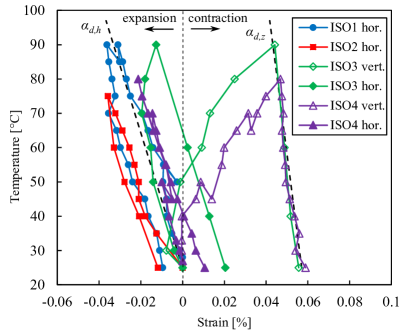
Perpendicular to bedding, the material first expanded with temperature up to 40 , followed by contraction at higher temperatures. During cooling, one can observe a linear contraction, providing an average linear thermal expansion coefficient from tests ISO3 and ISO4. Note that this thermal expansion coefficient is about 2.4 times smaller than that measured parallel to bedding. This gives a bulk thermal expansion coefficient .
To describe the observed contraction during heating, we use an elasto-plastic drained thermal expansion coefficient , which includes reversible () and irreversible () thermal strains (Sulem et al., 2007). We can adopt a linear relationship from the measurements on samples ISO3 and ISO4, found by a least square error fitting on the data in Fig. 10:
| (13) |
with in from 25 to 90 , providing the value of the irreversible thermal expansion coefficient:
| (14) |
4.2 Undrained thermal deformations
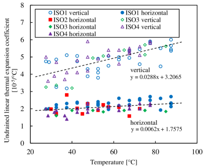
During the first phase of each temperature step, the undrained thermal expansion coefficients were determined from the tangent of the strain-temperature curves. All four specimens showed a similar behaviour with axial strains about 2.3 times higher than radial ones, and an average value (from 3 samples) and (from 4 samples). By carrying out step tests at different temperatures, we can present the changes in thermal expansion coefficients with respect to temperature, as seen in Fig. 11. The observed scatter of data can originate from the natural variability of properties, non-linearities of thermal expansion and measurement uncertainties due to the small deformations mobilized. For instance, the scatter in vertical direction corresponds to around 0.5 m total vertical displacement on a 10 mm high specimen during a heating step of 5. Note that the values of the undrained thermal expansion coefficients are nearly one order of magnitude higher than the drained ones shown before. An increase in both vertical and horizontal thermal expansion coefficients with temperature was observed. A linear temperature relationship of and is found by a least square error fit (Fig. 11), and described with the following functions:
| (15) |
| (16) |
with in from 25 to 90 .
This also provides an expression for the volumetric undrained thermal expansion coefficient :
| (17) |
This linear relationship is depicted in Fig. 12 together with the measured bulk thermal expansion coefficients. Note that, due to the absence of radial measurements on ISO2, the volumetric response could not be displayed for this specimen.
We could not detect any notable difference between undrained thermal expansion coefficients during heating and cooling, showing that thermoplastic deformations were not significant in undrained conditions. As shown in Fig. 10, the deformations of the solid matrix (,) contain some thermoplastic characteristics, but since is about ten times smaller than , their effects on the latter are not significant. We can conclude, that undrained thermal strains are mainly governed by the reversible thermal volume changes of the fluid phase.
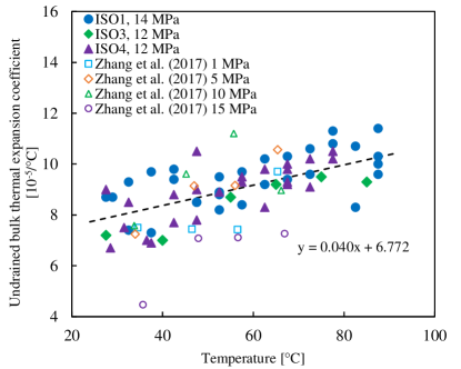
Comparable data on the undrained thermal bulk expansion coefficient of COx specimens have been presented by Zhang et al. (2017). Their results under different confining stresses show values close to the ones obtained in this study, indicating also an increase of with temperature (Fig. 12). Mohajerani et al. (2012) investigated the undrained thermal behaviour of two COx samples in an isotropic cell. They did not record any specimen deformations, but they performed a back-calculation of based on their measurements of induced pore pressures due to thermal pressurization. This theoretical increased with temperature, with about (close to our findings) at 30 and 8 MPa effective stress, up to about (much higher than our findings) at 80 and 3.4 MPa effective stress.
4.3 Strain response to pore pressure change
By changing the pore pressure under isostatic and isothermal conditions, one can measure the Biot modulus . This was done, once the undrained equilibrium was reached in each three-stage step test, by opening the drainage system and bringing the thermally induced pore pressure back to initial value (see Fig. 8 and 9).
Note that the thermoplastic response observed above 40 could not provide along heating paths, because is an elastic property. Consequently, above 40 , was determined from cooling paths only.
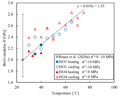
As one can observe in Fig. 13, the measured moduli appear to increase with temperature. The reported significant scatter of data is probably due to the natural variability of the material property, non-linear behaviour and measurement uncertainties on the relatively small deformations. The values at ambient temperature are in agreement with the findings of our companion paper (Braun et al., 2020a), where a mean value of around 1.99 GPa (for isotropic effective stresses between 8 and 10 MPa at 25 ) was presented. This evaluation was based on direct measurements and on a regression of various measured poroelastic properties. In the companion paper (Braun et al., 2020a), one can observe however some variability of measured moduli at the same stress state, indicated in Fig. 13. The values measured in the present work lie almost all within this range, making it difficult to identify a clear temperature dependency.
4.4 Thermally induced pore pressure
Using the calibration presented in Sec. 3.3, we corrected the thermal pressurization coefficients, measured from the temperature steps applied on samples ISO1 and ISO4. However, this correction method is based on the assumption of a thermo-elastic response, which was not the case during heating over 40 . Therefore, we show in Fig. 14 the corrected results obtained along heating paths below 40 and along cooling paths, during which the response is considered as thermo-elastic. One can observe reasonable agreement between the data from heating below 40 and from the cooling phases.
We can see that the parameter increases significantly with temperature, with values of around 0.12 MPa/ at 25 and up to around 0.30 MPa/ at 80 . Note that the effective stress conditions for these measurements remained nearly constant, close to the in-situ ones. The total stress was kept constant, while the thermally induced pore pressures were released after each step.
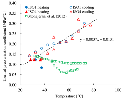
Mohajerani et al. (2012) measured thermal pressurization coefficients of two COx specimens, heated under initially close to in-situ stress ( 8 MPa). During the experiment, decreased slightly with temperature, with about 0.14 MPa/ at 25 down to between 0.10 and 0.05 MPa/ above 70 . As seen in Fig. 14, their results for temperature below 40 ∘C correspond well to the findings of this study, however one can observe a large difference at higher temperatures. This difference will be discussed in more details in Sec. 5.4.
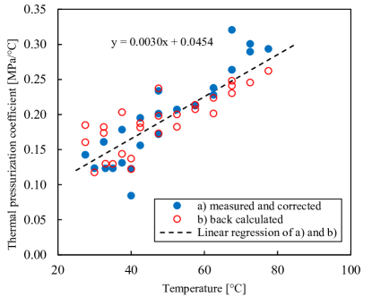
In parallel, we use Eq. (10) to compute for each step test carried out within the thermo-elastic regime, based on the measurements of , and from each respective test. As seen in Fig. 15, these calculated values show good overall compatibility with the corrected measurements. Only the measured values for temperatures over 70 appear to be slightly higher than the calculated ones. The observed scatter of the datapoints on the thermal pressurization coefficient and the differences between measured/corrected and back-calculated values are probably due to the combined error of the various thermo-poromechanical properties involved in the correction (Eq. (11)) or in the back-calculation (Eq. (10)).
5 Discussion
5.1 Thermal strains of the solid matrix
Within a thermo-poromechanical framework, assuming micro-homogeneity, one can assume . The drained thermoelastic expansion coefficient of a specimen is therefore equal to the thermal volume changes of the solid matrix . In the case of COx claystone, for which we measured (perpendicular to bedding) and (parallel to bedding), the solid phase is composed of around 42 clay minerals, 30 calcite, 25 quartz and 4 feldspar (Conil et al., 2018).
| Mineral | Mass-% | |||
|---|---|---|---|---|
| bulk | linear () | linear () | ||
| Clay | 42 | 2.48 | 1.78 1 | 0.35 1 |
| (muscovite) | ||||
| Quartz | 25 | 3.3 2 | 1.1 | |
| Calcite | 30 | 1.4 3 | 0.5 | |
| Feldspar | 4 | 1.1 3 | 0.4 | |
| COx claystone | 1.23 4 | 0.21 4 | 0.51 4 | |
| 1McKinstry (1965), 2Palciauskas and Domenico (1982), | ||||
| 3Fei (1995), 4this study | ||||
McKinstry (1965) measured the thermal expansion of clay minerals using a X-ray method. He provided mean values for muscovite, a mineral with the same molecular organisation as illite and smectite, of 1.78 perpendicular to the layer and of 0.35 parallel to the layer. Fei (1995) gave values for the volumetric thermal expansion of calcite (1.4 ) and feldspar (1.1 ), and Palciauskas and Domenico (1982) for quartz (3.3 ) (see Tab. 3 for an overview).
The thermal expansion coefficients of the mineral constituents of the COx claystone are compared in Tab. 3 with the measured drained thermal expansion coefficients. One can see that the drained thermal expansion coefficient parallel to bedding (0.51 ) lies within in the range of the values of elementary minerals (0.35 - 1.1 ). The reversible thermal expansion coefficient perpendicular to bedding (0.21 ) is however smaller than that of the mineral constituents (0.4 - 1.78 ). This fact, together with the contraction observed along heating paths perpendicular to bedding, shows that strains in this direction are not only dependent on the thermo-elastic behaviour of the minerals. Given the preferred sub-horizontal orientation of the clay platelets, we assume that adsorbed water molecules, either within the platelets or in the inter-platelets porosity, could have an influence on thermal strains perpendicular to bedding. Also the possible exchange of water between the solid phase and the bulk water through sorption is not captured by our model. The sorption potential has been found highest on smectites compared to other clay minerals, which are found in the form of 10-24 % interstratified illite/smectite layers in the COx matrix. Note that the sorption potential can be also temperature dependent, which could be a responsible mechanism behind the observed nonlinear thermoplasticity (e.g. Brochard et al., 2017; Liu et al., 2018).
5.2 Parametric study of THM couplings
Looking at the thermoelastic expression of given in Eq. (8), one observes that the parameter is mainly depending on the difference between the thermal expansion of pore fluid and of the solid matrix . The unjacketed modulus , the fluid bulk modulus , the Biot modulus and the porosity are also involved in the expression of .
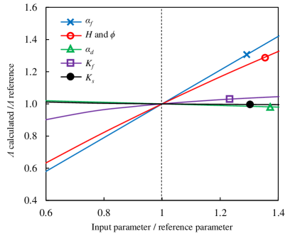
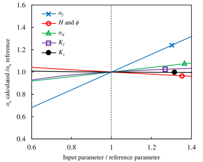
A sensitivity analysis was carried out by calculating with Eq. (8), and with Eq. (10), using the previously considered reference parameters presented in Tab. 4. The influences of separate variation of each input parameter on and are shown in Fig. 16 and 17, respectively. One observes little sensitivity of both parameters with respect to , and . Conversely, the thermal pressurization coefficient is strongly dependent on the parameters , and , with the highest effect caused by . We can also see that is less sensitive to changes in and , showing that is the single main parameter governing the changes in .
| 1.23 | measured | ||
|---|---|---|---|
| 2.60 | IAPWS-IF97 (2008) | ||
| 21.0 | Belmokhtar et al. (2017b) | ||
| 2.2 | IAPWS-IF97 (2008) | ||
| 18.0 | measured | ||
| 1.99 | Braun et al. (2020a) |
5.3 Anomalous thermal behaviour of pore fluid
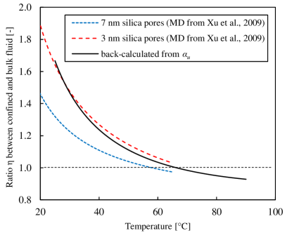
Baldi et al. (1988) observed on low porosity clays, that the experimentally measured undrained response could only be reproduced by utilizing a thermal expansion coefficient of the pore fluid, higher than that of free water. In the case of Opalinus clay, Monfared et al. (2011) observed the same phenomenon and back-calculated a thermal expansion coefficient of the pore fluid about two times higher than that of free water. Valenza and Scherer (2005) reported an anomalous thermal expansion of water, confined in cement pores, based on their thermopermeametry and beam bending experiments, while Ghabezloo et al. (2009b) confirmed such findings with measurements from undrained heating tests on hardened cement paste. In laboratory experiments on silica gel and silica glasses, respectively, Derjaguin et al. (1992) and Xu et al. (2009) could measure an elevated thermal expansion coefficient of the water contained in these small pores of nano-scale. Derjaguin et al. (1992) noted that, starting from 70 , the confined water lost its anomalous characteristics. Xu et al. (2009) were able to simulate their laboratory experiments up to 40 by molecular dynamics calculations up to around 60 . Their extrapolation for higher temperatures, presented in Fig. 18, also show that the thermal expansion coefficient of confined water became equal to that of bulk water at around 70 .
To analyse the thermal expansion property of COx pore fluid, we utilize the strong coupling between and (Fig. 17). This allows us to carry out a back-analysis of , using the experimentally determined , by rewriting Eq. (10) and (8):
| (18) |
We utilize Eq. (18) to calculate the thermal expansion coefficient of the pore fluid, under constant confining stress and pore pressure, as a function of temperature. The parameters of Tab. 4 are used here, taking into account the temperature and stress dependency of (IAPWS-IF97, 2008). For , we use the value at ambient temperature from Tab. 4 and combine it with the observed temperature dependency (Fig. 13) to obtain , with in GPa and in . Also the experimentally determined undrained thermal expansion coefficient (Fig. 12) is inserted in Eq. (18). Doing so, we obtain a pore fluid thermal expansion coefficient , which is highly temperature dependent, and differs from the thermal expansion coefficient of free water. We introduce a factor (calulated)/(bulk water), which is shown in Fig. 18. For ambient temperatures, the pore fluid expands around 1.7 times more than bulk water. The ratio decreases with increasing temperature. For temperatures over 60 , the thermal expansion coefficient of the pore fluid is slightly lower than that of free water (). A comparison with the values presented by Xu et al. (2009) shows a good agreement. This indicates a very peculiar behaviour of the water confined in the COx pores, to which also the sorption behaviour of the 10-24 % mixed illite/smectite content could be contributing. A potential release of adsorbed water molecules from the solid phase to the fluid phase could be a reason for the increasing pore water volume expansion, which is not captured by the thermo-poro-elastic model.
5.4 Stress and temperature dependent thermal pressurization
To investigate the stress and temperature dependency of the thermal pressurization coefficient, we insert in Eq. (8) the previously back-calculated elevated thermal expansion coefficient of the pore fluid (Fig. 18). Again, the temperature and stress dependency for (IAPWS-IF97, 2008) was considered. For the Biot modulus , we use the following stress-dependent relationship from Braun et al. (2020a):
| (19) |
with in GPa and in MPa. By assuming this stress dependency to be valid for all temperatures, we can add the temperature dependent part observed in this study (Fig. 13):
| (20) |
with , in GPa and in , obtained by a least square error fit. Other coefficients were taken from Tab. 4. A significant increase of with temperature due to an increasing can be noticed in Fig. 19a (blue solid line). We compare these values to our measurements (which were corrected for the effects of the drainage system, see Sec. 3.3) and to the calculated values from direct measurements using Eq. (10), also presented in Fig. 19a. A good agreement between these values at temperatures up to 60 can be observed. For higher temperatures however, the back calculation underestimates slightly the measured thermal pressurization.
Using the same parameters, but changing the stress conditions according to the experiment carried out by Mohajerani et al. (2012), we are able to reproduce a similar nearly constant parameter , plotted in Fig. 19a. Here we calculated through Eq. (8), first for 8 25 . Then was computed subsequently with 1 . The changed stress conditions, which include a continuously increasing pore pressure (according to ) reducing the effective stress, mainly affect the parameter . A decreasing results here in a thermal pressurization coefficient, which remains nearly constant, evidencing a strong stress dependency of . Another calculation for a constant, but very low effective stress, is presented in Fig. 19a. Due to constant effective stress, we see again an increasing thermal pressurization coefficient, with however much lower values. Due to the decreasing effective stress, the material becomes more compliant. The increase of the fluid thermal expansion coefficient with temperature is counterbalanced by the higher mechanical deformation of the pore space.
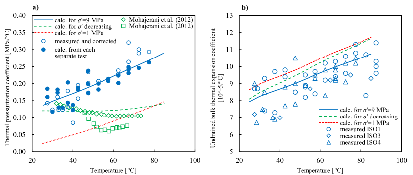
The effect of stress on was investigated by calculating using Eq. (9) and (10), as shown in Fig. 19b. Unsurprisingly, since the measured mean values of were used as input parameters for the model, we find a good agreement for the calculation at MPa. More interestingly, we observe only a small stress dependency of at MPa, which lies within the range of variability of measured values. The plot for a decreasing effective stress represents, as also for the thermal pressurization coefficients in Fig. 19a, some transition between the limiting curves at 9 and 1 MPa effective stress.
6 Conclusions
Time saving testing protocols for thermal laboratory experiments, together with an optimized experimental device, allowed us to efficiently determine the thermal properties of the COx claystone on four specimens. A modified testing apparatus with a reduced drainage length permitted relatively fast specimen saturation and drainage times. The application of the protocols of Braun et al. (2019) provided multiple material parameters in each experiment, rendering the laboratory study more time efficient. Strain gages were employed for measuring precise specimen deformations, where it was crucial to account for thermally induced measurement errors, especially due to the relatively small thermal strain response of the tested material. Reversible drained thermal strains, parallel to the bedding plane, were detected during heating and cooling up to 90 . In the perpendicular direction, we observed a thermal contraction upon heating, which appeared to be irreversible. During cooling, the material contracted in both directions, with strains parallel to bedding about 2.4 times higher than perpendicular to bedding. A relatively small reversible volumetric drained thermal expansion coefficient was found. The undrained thermal expansion coefficient during heating and cooling under constant stress conditions was determined, and found to increase with temperature. A good compatibility with the transversely isotropic drained and undrained thermal expansion coefficients and the Biot modulus , which were simultaneously measured for each test, gives confidence in the measured properties. By conducting a back analysis, we showed that for reproducing the undrained thermal expansion coefficient and the thermal pressurization coefficient in a thermo-poro-elastic framework, one has to consider a thermal expansion coefficient of the pore water greater than that of bulk water. Together with the measured Biot modulus and the measured drained thermal expansion coefficient , the thermal pressurization coefficient was calculated. The theoretical values reflect well experimental results, and can reproduce a thermal pressurization coefficient that increases significantly with temperature and decreases with decreasing effective stress. By decreasing the effective stress during undrained heating, the material stiffness decreases, expressed through , which results in a nearly constant thermal pressurization coefficient. One can also note that undrained characteristics (, ) were insensitive to , due to the relatively small values of . This emphasizes the decisive role of pore fluid in the undrained thermal behaviour of the COx claystone. The anomalous thermal fluid expansion, the thermoplastic behaviour of the solid matrix and the coupling with stress dependent poroelastic properties should be considered in engineering models, when analysing the response of the formation to thermal loading.
Conflict of interest
The authors declare that there are no known conflicts of interest associated with this publication.
References
- Abuel-Naga et al. (2007) Abuel-Naga HM, Bergado DT, Bouazza A (2007) Thermally induced volume change and excess pore water pressure of soft bangkok clay. Engineering Geology 89(1-2):144–154
- Andra (2005) Andra (2005) Dossier 2005 Argile: Evaluation of the feasibility of a geological repository in an argillaceous formation. URL https://international.andra.fr/sites/international/ files/2019-03/3- Dossier 2005 Argile Synthesis - Evaluation of the feasibility of a geological repository in an argillaceous formation_0.pdf
- Armand et al. (2017) Armand G, Bumbieler F, Conil N, de la Vaissière R, Bosgiraud JM, Vu MN (2017) Main outcomes from in situ thermo-hydro-mechanical experiments programme to demonstrate feasibility of radioactive high-level waste disposal in the Callovo-Oxfordian claystone. Journal of Rock Mechanics and Geotechnical Engineering 9(3):415–427
- Baldi et al. (1988) Baldi G, Hueckel T, Pellegrini R (1988) Thermal volume changes of the mineral–water system in low-porosity clay soils. Canadian Geotechnical Journal 25(4):807–825
- Belmokhtar et al. (2017a) Belmokhtar M, Delage P, Ghabezloo S, Conil N (2017a) Thermal Volume Changes and Creep in the Callovo-Oxfordian Claystone. Rock Mechanics and Rock Engineering 50(9):2297–2309
- Belmokhtar et al. (2017b) Belmokhtar M, Delage P, Ghabezloo S, Tang AM, Menaceur H, Conil N (2017b) Poroelasticity of the Callovo-Oxfordian Claystone. Rock Mechanics and Rock Engineering 50(4):871–889
- Biot and Willis (1957) Biot MA, Willis DG (1957) The Elastic Coefficients of the Theory of Consolidation. Journal of Applied Mechanics 24:594–601
- Bishop (1976) Bishop AW (1976) The influence of system compressibility on the observed pore-pressure response to an undrained change in stress in saturated rock. Géotechnique 26(2):371–5
- Blaise et al. (2014) Blaise T, Barbarand J, Kars M, Ploquin F, Aubourg C, Brigaud B, Cathelineau M, Albani AE, Gautheron C, Izart A, Janots D, Michels R, Pagel M, Pozzi JP, Boiron MC, Landrein P (2014) Reconstruction of low temperature (100 ∘C) burial in sedimentary basins: A comparison of geothermometer in the intracontinental paris basin. Marine and Petroleum Geology 53:71 – 87
- Braun et al. (2019) Braun P, Ghabezloo S, Delage P, Sulem J, Conil N (2019) Determination of Multiple Thermo-Hydro-Mechanical Rock Properties in a Single Transient Experiment: Application to Shales. Rock Mechanics and Rock Engineering 52(7):2023––2038
- Braun et al. (2020a) Braun P, Ghabezloo S, Delage P, Sulem J, Conil N (2020a) Transversely isotropic poroelastic behaviour of the callovo-oxfordian claystone: A set of stress-dependent parameters. Rock Mechanics and Rock Engineering p 1–20, DOI 10.1007/s00603-020-02268-z
- Brochard et al. (2017) Brochard L, Honorio T, Vandamme M, Bornert M, Peigney M (2017) Nanoscale origin of the thermo-mechanical behavior of clays. Acta Geotechnica 12(6):1261–1279
- Brown and Korringa (1975) Brown RJS, Korringa J (1975) On the dependence of the elastic properties of a porous rock on the compressibility of the pore fluid. Geophysics 40(4):608–616
- Cheng (1997) Cheng AHD (1997) Material coefficients of anisotropic poroelasticity. International Journal of Rock Mechanics and Mining Sciences 34(2):199–205
- Chiarelli (2000) Chiarelli AS (2000) Étude expérimentale et modélisation du comportement mécanique de l’argilite de l’Est, Influence de la profondeur et de la teneur en eau. PhD thesis, Université Lille I
- Conil et al. (2018) Conil N, Talandier J, Djizanne H, de La Vaissière R, Righini-Waz C, Auvray C, Morlot C, Armand G (2018) How rock samples can be representative of in situ condition: A case study of Callovo-Oxfordian claystones. Journal of Rock Mechanics and Geotechnical Engineering 10(4):613–623
- Coussy (2004) Coussy O (2004) Poromechanics. J. Wiley & Sons, New York
- Delage et al. (2000) Delage P, Sultan N, Cui YJ (2000) On the thermal consolidation of Boom clay. Canadian Geotechnical Journal 37(2):343–354
- Derjaguin et al. (1992) Derjaguin BV, Karasev VV, Khromova EN (1992) Thermal expansion of water in fine pores. Progress in Surface Science 40(1-4):391–392
- Escoffier (2002) Escoffier S (2002) Caractérisation expérimentale du comportement hydroméchanique des argilites de Meuse/Haute-Marne. PhD thesis, Institut National Polytechnique de Lorraine
- Ewy (2015) Ewy RT (2015) Shale/claystone response to air and liquid exposure, and implications for handling, sampling and testing. International Journal of Rock Mechanics and Mining Sciences 80:388–401
- Favero et al. (2018) Favero V, Ferrari A, Laloui L (2018) Anisotropic Behaviour of Opalinus Clay Through Consolidated and Drained Triaxial Testing in Saturated Conditions. Rock Mechanics and Rock Engineering 51(5):1305–1319
- Fei (1995) Fei Y (1995) Thermal expansion. In: Ahrens TJ (ed) Mineral Physics & Crystallography: A Handbook of Physical Constants, American Geophysical Union, pp 29–44
- Gaucher et al. (2004) Gaucher E, Robelin C, Matray JM, Négrel G, Gros Y, Heitz JF, Vinsot A, Rebours H, Cassagnabère A, Bouchet A (2004) ANDRA underground research laboratory : interpretation of the mineralogical and geochemical data acquired in the Callovian – Oxfordian formation by investigative drilling. Physics and Chemistry of the Earth 29(1):55–77
- Gens et al. (2007) Gens A, Vaunat J, Garitte B, Wileveau Y (2007) In situ behaviour of a stiff layered clay subject to thermal loading: observations and interpretation. Géotechnique 57(2):207–228
- Ghabezloo and Sulem (2009) Ghabezloo S, Sulem J (2009) Stress dependent thermal pressurization of a fluid-saturated rock. Rock Mechanics and Rock Engineering 42(1):1–24
- Ghabezloo and Sulem (2010) Ghabezloo S, Sulem J (2010) Effect of the volume of the drainage system on the measurement of undrained thermo-poro-elastic parameters. International Journal of Rock Mechanics and Mining Sciences 47(1):60–68
- Ghabezloo et al. (2009a) Ghabezloo S, Sulem J, Saint-Marc J (2009a) Evaluation of a permeability-porosity relationship in a low-permeability creeping material using a single transient test. International Journal of Rock Mechanics and Mining Sciences 46(4):761–768
- Ghabezloo et al. (2009b) Ghabezloo S, Sulem J, Saint-Marc J (2009b) The effect of undrained heating on a fluid-saturated hardened cement paste. Cement and Concrete Research 39(1):54–64
- Hart and Wang (1995) Hart DJ, Wang HF (1995) Laboratory measurement of a complete set of poroelastic moduli for Berea sandstone and Indiana limestone. Journal of Geophysical Research 100:741–751
- IAPWS-IF97 (2008) IAPWS-IF97 (2008) IAPWS Industrial Formulation 1997 for the Thermodynamic Properties of Water and Steam. Springer, Berlin, Heidelberg
- Liu et al. (2018) Liu J, Fokker PA, Peach CJ, Spiers CJ (2018) Applied stress reduces swelling of coal induced by adsorption of water. Geomechanics for Energy and the Environment 16:45–63
- Martin (1962) Martin RT (1962) Adsorbed Water on Clay: A Review. Clays and clay minerals pp 28–70
- McKinstry (1965) McKinstry HA (1965) Thermal Expansion of Clay Minerals. The American Mineralogist 50(1-2):212–222
- Menaceur et al. (2015) Menaceur H, Delage P, Tang AM, Conil N (2015) The thermo-mechanical behaviour of the Callovo-Oxfordian claystone. International Journal of Rock Mechanics and Mining Sciences 78:290–303
- Menke (1989) Menke W (1989) Geophysical data analysis: Discrete inverse theory. Academic Press Limited, London
- Mohajerani et al. (2011) Mohajerani M, Delage P, Monfared M, Tang AM, Sulem J, Gatmiri B (2011) Oedometric compression and swelling behaviour of the Callovo-Oxfordian argillite. International Journal of Rock Mechanics and Mining Sciences 48(4):606–615
- Mohajerani et al. (2012) Mohajerani M, Delage P, Sulem J, Monfared M, Tang AM, Gatmiri B (2012) A laboratory investigation of thermally induced pore pressures in the Callovo-Oxfordian claystone. International Journal of Rock Mechanics and Mining Sciences 52:112–121
- Mohajerani et al. (2014) Mohajerani M, Delage P, Sulem J, Monfared M, Tang AM, Gatmiri B (2014) The thermal volume changes of the Callovo-Oxfordian claystone. Rock Mechanics and Rock Engineering 47(1):131–142
- Monfared et al. (2011) Monfared M, Sulem J, Delage P, Mohajerani M (2011) A Laboratory Investigation on Thermal Properties of the Opalinus Claystone. Rock Mechanics and Rock Engineering 44(6):735–747
- Palciauskas and Domenico (1982) Palciauskas VV, Domenico PA (1982) Characterization of drained and undrained response of thermally loaded repository rocks. Water Resources Research 18(2):281–290
- Popov et al. (2019) Popov VL, Heß M, Willert E (2019) Transversely Isotropic Problems, Springer Berlin Heidelberg, Berlin, Heidelberg, pp 205–212
- Rad and Clough (1984) Rad NS, Clough GW (1984) New procedure for saturating sand specimens. Journal of Geotechnical Engineering 110(9):1205–1218
- Seyedi et al. (2017) Seyedi D, Armand G, Conil N, Vitel M, Vu MN (2017) On the Thermo-Hydro-Mechanical Pressurization in Callovo-Oxfordian Claystone under Thermal Loading. Poromechanics 2017 - Proceedings of the 6th Biot Conference on Poromechanics pp 754–761
- Sulem et al. (2007) Sulem J, Lazar P, Vardoulakis I (2007) Thermo-poro-mechanical properties of clayey gouge and application to rapid fault shearing. International Journal for Numerical and Analytical Methods in Geomechanics 31(3):523–540
- Sultan et al. (2002) Sultan N, Delage P, Cui YJ (2002) Temperature effects on the volume change behaviour of boom clay. Engineering Geology 64(2-3):135–145
- Tang et al. (2008) Tang AM, Cui YJ, Barnel N (2008) Thermo-mechanical behaviour of a compacted swelling clay. Géotechnique 58(1):45–54
- Valenza and Scherer (2005) Valenza JJ, Scherer GW (2005) Evidence of anomalous thermal expansion of water in cement paste. Cement and Concrete Research 35(1):57–66
- Wileveau et al. (2007) Wileveau Y, Cornet FH, Desroches J, Blumling P (2007) Complete in situ stress determination in an argillite sedimentary formation. Physics and Chemistry of the Earth 32(8-14):866–878
- Wissa (1969) Wissa AEZ (1969) Pore pressure measurement in saturated stiff soils. Journal of the Soil Mechanics and Foundations Division 95(4):1063–1073
- Xu et al. (2009) Xu S, Scherer GW, Mahadevan TS, Garofalini SH (2009) Thermal expansion of confined water. Langmuir 25(9):5076–5083
- Zhang et al. (2017) Zhang CL, Conil N, Armand G (2017) Thermal effects on clay rocks for deep disposal of high-level radioactive waste. Journal of Rock Mechanics and Geotechnical Engineering 9(3):463–478
- Zhang et al. (2012) Zhang F, Xie SY, Hu DW, Shao JF, Gatmiri B (2012) Effect of water content and structural anisotropy on mechanical property of claystone. Applied Clay Science 69:79–86