PON Virtualisation with EAST-WEST Communications for Low-Latency Converged Multi-Access Edge Computing (MEC)
Sandip Das, Marco Ruffini
CONNECT Center, Trinity College Dublin
dassa@tcd.ie, marco.ruffini@tcd.ie
Abstract
We propose a virtual-PON based Mobile Fronthaul (MFH) architecture that allows direct communications between edge points (enabling EAST-WEST communication). Dynamic slicing improves service multiplexing while supporting ultra-low latency under 100s between cells and MEC nodes.
OCIS codes: 060.4250, 060.4510.
- QoS
- Quality of Service
- C-RAN
- Cloud Radio Access Networks
- FBG
- Fibre Bragg Grating
- MFH
- Mobile Fronthaul
- RU
- Radio Unit
- BBU
- Baseband Unit
- DU
- Distributed Unit
- CU
- Central Unit
- PON
- Passive Optical Network
- vPON
- virtual-PON
- ODN
- Optical Distribution Network
- TWDM
- Time-Wavelength Division Multiplexing
- DBA
- Dynamic Bandwidth Allocation
- MEC
- Multi Access Edge Computing
- CO
- Central Office
- OLT
- Optical Line Terminal
- ONU
- Optical Networking Unit
- PLOAM
- Physical Layer Operation and Maintenance
- eCPRI
- evolved Common Public Radio Interface
- BS
- Base Station
- TDMA
- Time Division Multiple Access
- TTI
- Transmit Time Interval
- VRF
- Variable Rate Fronthaul
- vPON
- Virtualized PON
- UE
- User Equipment
- LLS
- Low Layer Split
- WLB
- Wavelength Loop Back
- WPF
- Wavelength Pass Filter
1 Introduction
In the 5G era of telecommunications, characterised by diversified service requirements, low-latency and deterministic Quality of Service (QoS) are two most crucial network requirements. With the drive towards Cloud Radio Access Networks (C-RAN) to support these requirements, building a reliable and low-cost fronthaul transport network becomes a significant issue. For example, a C-RAN that uses eCPRI (the evolved CPRI standard for 5G networks) has a very stringent latency requirement of 100 for any split that is below the MAC layer. In order to achieve this low transport network latency, the transmission distance between the cell site ( Radio Unit (RU)) and the first processing site ( Distributed Unit (DU)) is made shorter by deploying some limited capacity cloud processing resources (called Multi Access Edge Computing (MEC)) close to the cell-sites.
As 5G networks will bring a progressive densification of mobile cells, the cost of the optical transport network will soar to unsustainable levels, if cells are connected through dedicated point-to-point fibre. In addition, point-to-point solutions provide little flexibility in redirecting RU connectivity between edge cloud nodes during migration events. For this reason, Passive Optical Network (PON), typically used for providing broadband to residential and small business users, is being considered as a possible cost-effective solution to support optical Mobile Fronthaul (MFH) transport, as it can use an already deployed Optical Distribution Network (ODN) to provide fronthaul transport for RUs along with serving residential users. However, achieving low latency is a major challenge for PONs in the upstream direction, because of its Time Division Multiple Access (TDMA) nature of operation. A solution was proposed in [1] and recently standardised by ITU-T [2], called cooperative DBA, which adopts a mechanism where User Equipment (UE) scheduling information is passed directly from the DU to the Optical Line Terminal (OLT). This bypasses the report/grant mechanism, thus enabling low MFH transport latency.
While this workaround solves the latency issue when Optical Networking Units are connected to a given OLT in a Central Office (CO), where also the DU and Central Unit (CU) processing are located, it does not provide a solution for edge cloud environments, where the DU processing might migrate across edge nodes, for example for load balancing or to support low latency also at the application level.
In this work, we propose a novel architecture, based on PON virtualisation, which also enables EAST-WEST PON communication. This enables end points, where typically only end users or RUs would be located, to also host edge nodes. In this way, for example, RUs can dynamically redirect their connection from DUs/CUs located at the central offices (i.e., at the source of the PON tree) towards ones located at the edge (i.e., at the leaves of the PON tree). This largely improves the statistical multiplexing ability of the PON to support low-latency services. While the concept of dynamic Virtualized PON (vPON) was also proposed in [3], there the authors restrict the location of edge nodes to the splitter nodes and consider dynamic offloading only between edge nodes and CO.
Our work introduces instead the ability to create virtual PONs across a mix of CO and edge nodes, which can be located anywhere in the PON. In addition, we propose a novel CO-assisted dynamic vPON slice formation mechanism for offloading ONUs between edge OLTs, to provide ultra-low end-to-end transport latency for MFH.
2 Proposed vPON architecture for MEC support through EAST-WEST communication
Fig. 1 illustrates the system architecture of our proposed MFH over a C-RAN scenario. We consider a Time-Wavelength Division Multiplexing (TWDM)-PON based mobile fronthaul network, shared with residential users, as shown in the Fig. 1(a). RUs are connected with DUs through a two-stage splitter hierarchy. While our architecture can support multiple scenarios of edge cloud convergence, in this work we consider a popular mobile cell placement strategy, where several small cells are deployed to provide offload capability to a macro cell. Further, we consider that MEC servers with limited processing capacity are deployed at the macro-cell sites in order to process delay-sensitive traffic. The level-1 splitter connects all the RUs belonging to the coverage area of each macrocell. We refer to this as level-1 PON tree. The level-2 splitter interconnects the level-1 splitters to the CO. However, unlike [3], we propose an interconnection between level-1 splitters to establish communication between level-1 PON branches. It is important to emphasise that this interconnection can be implemented either through direct cable routes between level-1 splitters or else, if existing ducts are not available, as an overlay over the existing level-1 to level-2 splitters’ fiber routes (the difference in performance is shown later in Fig. 4). Fig. 1(b) presents the architecture of the proposed level-1 splitter.
Each level-1 splitter uses three additional blocks namely Wavelength Loop Back (WLB), Wavelength Pass Filter (WPF)1 and WPF2, where is the operating wavelength of the edge OLT. Each block connects to the upper side of the splitter, which can have as many ports as there are on the lower side (splitter are inherently symmetrical in this sense). makes use of two reconfigurable Fibre Bragg Gratings connected through a coupler, a circulator and, where required (depending on the splitter loss), a semiconductor optical amplifier, to reflect back selected wavelengths towards the edge. Therefore, if the operating wavelength of the edge OLT is , (as in Fig. 1(b)), reflects back (for downstream) and (for upstream) towards the edge OLT. This enables the edge OLT to connect to the ONUs of its own level-1 PON tree (the vPON is shown as red shaded area in Fig. 1(a). let and pass through to connect to the upper side of the splitter of the adjacent level-1 PON tree, enabling the edge OLT to connect to the ONUs of its neighbouring level-1 PON tree (also shown as red shaded area). This enables a vPON that has more than one edge OLT to communicate using the same wavelength. Similarly, let the operating wavelength of the edge-OLT of the adjacent level-1 PON tree ( and in this case) pass through, enabling the ONUs of the current Level-1 PON tree to send and receive upstream and downstream traffic to/from the neighbouring edge-OLT.
In addition, if more capacity is required, additional wavelengths (e.g., ) can be provisioned for the communications to edge OLTs in the adjacent PON branch.
The CO-OLT can employ a one-channel XGS-PON or a TWDM PON with four (or more) wavelengths () for upstream and downstream. is dedicated for exchanging control information such as wavelength reconfiguration and vPON slice information in the MFH with small cell ONUs and edge OLTs. The surplus bandwidth of along with is shared with other users. In order to dynamically connect to the edge OLT and CO-OLT, each small cell ONU employs one fixed (i.e., to reduce cost) and one tunable transceiver, so that a control channel to the CO is always available.The edge OLT, hosting the MEC node, also employs a similar pair of transceiver structure with the fixed transceiver dedicated for control message exchange with CO-OLT and the tunable one used for the datapath of the dynamic vPON slices. Other residential ONUs can adopt single wavelength XGS-PON or else tunable TWDM, depending on their requirements (and suitable cost). The vPON slice allocation is carried out at the CO and communicated to the edge OLTs through Physical Layer Operation and Maintenance (PLOAM) messages from the OLTs located at the CO.
3 Performance Evaluation and Results
The topology we consider is that of a converged access/metro architecture [4, 5], where the main CO is located 50km away from the edge. Of this, 40 km are used by the main feeder fibre, 10 km by the distance between level-1 and level-2 splitters, while the distance from the last splitter to the edge is up to 500 meters. This is an example of a popular converged access/metro architecture [5], currently under standardisation, although the proposed system can support different distance distributions. We simulate the proposed architecture using the discrete event simulator OMNET++, where each wavelength channel follows the XGS-PON specification. The small cells implement C-RAN with Low Layer Split (LLS), as described in [6], where each RU is served by an ONU and the OLT, DU, and CU is either at the edge (MEC) or CO. The core network functions are hosted at the CO regardless of the placement of CU/DU. The traffic from RU to DU is modeled as evolved Common Public Radio Interface (eCPRI) traffic. We consider split-8, operating over a Variable Rate Fronthaul (VRF) scheme [7] and split-7.1 [6], both providing variable rate depending on the actual traffic at the cell. The user arrival process is modeled as a Poisson distribution. The fronthaul rates for split-7.1 are derived from [8]: as the cell bandwidth varies from 1.4 to 20MHz, for an RU having two antennas, the fronthaul rate for split-8 goes from 153 to 2,457 Mb/s, while the split-7.1 from 110 to 1,058 Mb/s.
The Dynamic Bandwidth Allocation (DBA) process works as follows. Each OLT with a prior scheduling information of UE from the CU (i.e., following the cooperative DBA approach [2]), schedules the entire eCPRI payload output of the ONU for the corresponding Transmit Time Interval (TTI) (1ms). Considering a DBA cycle of 125, the OLT is required to schedule the entire eCPRI payload over 8 grant cycles. As the RU requires some local processing time for the LLS functional split processing and the encapsulation of the eCPRI traffic, we model this with uniform distribution with an upper limit of 125 s.
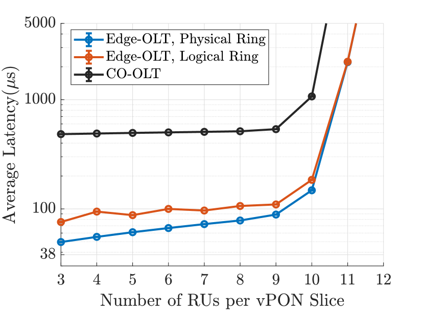
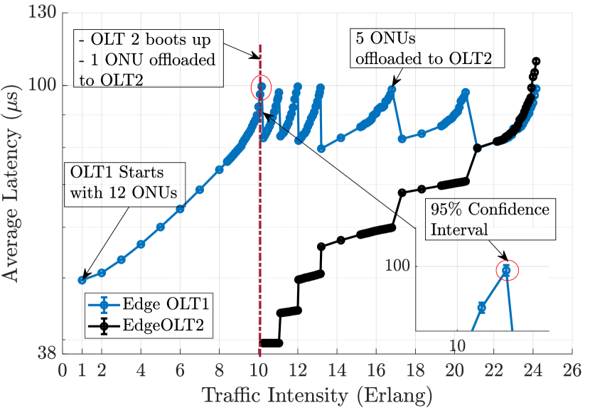
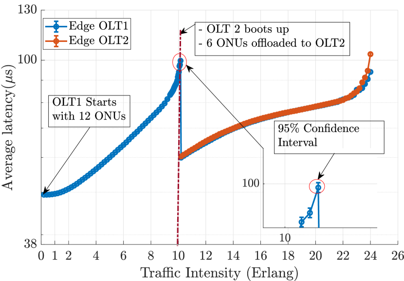
Fig. 4 shows a latency reduction of over 10 times between RU and DU, obtained by edge vPON slicing w.r.t. the use of OLTs located at the CO. The figure also shows the difference in latency when the fibre routes are overlaid on top of current PON routes (red curve), which is close to 100 , thus compatible with our selected threshold. Fig. 4, illustrates how our proposal can be exploited to considerably improve statistical multiplexing of cells through MEC migration of DUs, by dynamically reconfiguring vPON slices, depending on the traffic intensity reports from the DU. We consider two edge OLTs and 24 ONUs, where half of them are residential and served by the CO. Initially, at low traffic volumes, edge OLT1 starts with all the 12 C-RAN ONUs and we can see that the latency increases as the traffic at each RU increases. At 10 Erlang traffic per RU, the latency reaches our threshold, set at 100 (this value can be set to the most appropriate value required by the service). The CO thus activates edge OLT2 and reconfigures the vPON slices, offloading one ONU to the vPON slice served by OLT2. This causes a sharp reduction of uplink transport latency at OLT1. The process is then reiterated as soon as the latency grows close to the threshold level. Fig. 4 shows another strategy of balanced-load ONU offloading, where 6 of the 12 ONUs are offloaded simultaneously to the vPON slice corresponding to the OLT2, thereby reducing the frequency of offloading events. Although not shown here due to space constraints, we have verified experimentally that the backscattering from the WLB action does not affect the system performance, as we achieve a BER of for 10Gb/s transmissions rate even over a 10km (edge) transmission distance.
Acknowledgement
Financial support from SFI grants 14/IA/252 (O’SHARE) and 13/RC/2077 is gratefully acknowledged.
References
- [1] T. Tashiro et al., “A novel DBA scheme for TDM-PON based mobile fronthaul,” in OFC 2014.
- [2] “40-gigabit-capable passive optical networks: TC layer specification amd. 1,” ITU-T, Standard, Nov. 2016.
- [3] R. I. Tinini et al., “Low-latency and energy-efficient BBU placement and VPON formation in virtualized cloud-fog RAN,” JOCN, April 2019.
- [4] M. Ruffini et al., “Access and metro network convergence for flexible end-to-end network design,” JOCN, June 2017.
- [5] “IEEE p802.3cs increased-reach ethernet optical subscriber access (super-pon) task force,” Nov. 2018, http://www.ieee802.org/3/minutes/nov18/1118_spon_close_report.pdf.
- [6] N. Alliance, “NGMN Overview on 5g RAN Functional Decomposition,” Feb. 2018.
- [7] S. Das et al., “A Variable Rate Fronthaul Scheme for Cloud Radio Access Networks,” JLT, July 2019.
- [8] U. Dötsch et al., “Quantitative analysis of split base station processing and determination of advantageous architectures for lte,” Bell Labs Technical Journal, June 2013.