Dissipation-engineering of nonreciprocal quantum dot circuits: An input-output approach
Abstract
Nonreciprocal effects in nanoelectronic devices offer unique possibilities for manipulating electron transport and engineering quantum electronic circuits for information processing purposes. However, a lack of rigorous theoretical tools is hindering this development. Here, we provide a general input-output description of nonreciprocal transport in solid-state quantum dot architectures, based on quantum optomechanical analogs. In particular, we break reciprocity between coherently-coupled quantum dots by dissipation-engineering in which these (so-called) primary dots are mutually coupled to auxiliary, damped quantum dots. We illustrate the general framework in two representative multiterminal noninteracting models, which can be used as building blocks for larger circuits. Importantly, the identified optimal conditions for nonreciprocal behavior hold even in the presence of additional dissipative effects that result from local electron-phonon couplings. Besides the analysis of the scattering matrix, we show that a nonreciprocal coupling induces unidirectional electron flow in the resonant transport regime. Altogether, our analysis provides the formalism and working principles towards the realization of nonreciprocal nanoelectronic devices.
I Introduction
The ability to break reciprocity in nanoscale devices is crucial for quantum information processing and telecommunication, as the nonreciprocal functionality can protect active elements against extraneous noise. Reciprocity may be broken in various ways, such as by introducing asymmetry and nonlinearity, as in electrical and thermal diodes. Recently, significant attention has been given to engineering nonreciprocal transmission amplitudes in quantum optomechanical systems based on the interference between coherent couplings and dissipative effects Hafezi and Rabl (2012); Ranzani and Aumentado (2014, 2015); Metelmann and Clerk (2015); Ruesink et al. (2016); Xu et al. (2016, 2017a, 2017b); Shen et al. (2016); Bernier et al. (2017); Peterson et al. (2017); Fang et al. (2017); Barzanjeh et al. (2018); Malz et al. (2018); Xu et al. (2019). The analogous effect for electron transport is also highly desirable, as proposals for quantum information processing and computing platforms are based on electronic networks such as quantum dot arrays Loss and DiVincenzo (1998) or superconducting qubit circuits Devoret and Schoelkopf (2013). However, engineering nonreciprocal behavior in electronic systems—based on balancing coherent and dissipative couplings—remains almost unexplored, besides a recent study on a specific double quantum dot setup Malz and Nunnenkamp (2018). One concrete challenge is that for electron flow, one needs to control the charge current, which integrates over electrons in the full bias window, rather than only focus on the transmission probability at a particular energy. Much remains therefore to be learned about how to engineer nonreciprocal interactions in general electronic settings. Particularly, it is desirable to establish a simple yet general theoretical tool fitting for this task.
Here, we employ a recent theoretical advance, termed the generalized input-output method (GIOM) Liu and Segal (2020a, b) to address this challenge, and describe nonreciprocal nanoelectronic devices. Within the framework of the GIOM, the influence of fermionic environments exerted on electrons is encoded in generalized input and output fields, and the system dynamics is described by Heisenberg-Langevin equations (HLEs), thereby establishing a complete analogy to theoretical descriptions of quantum optomechanical systems. Building upon this input-output picture, we generate nonreciprocal couplings in electronic systems through dissipation engineering Metelmann and Clerk (2015). Focusing on solid-state quantum dot architectures, a simple yet general strategy to induce nonreciprocal coupling between quantum dots lies in building interference between coherent (Hamiltonian) inter-dot couplings and dissipative interactions. This interference is controlled by an applied, tunable magnetic field, which builds complex-valued coherent tunneling elements Malz and Nunnenkamp (2018).
We employ this mechanism in our setup by introducing primary and auxiliary quantum dots. The primary quantum dots construct the circuit of interest between two electrodes, termed ‘left’ () and ‘right’ (). To control the directionality of electrons towards say the electrode, the primary dots are mutually coupled to auxiliary quantum dots, which experience strong dissipation (loss) induced by additional fermionic reservoirs. In the large damping limit, one can adiabatically eliminate the auxiliary dots, resulting in an effective dissipative interaction between primary quantum dots. Nonreciprocal coupling is generated by balancing this induced dissipative interaction against the inherent coherent hopping processes, and the directionally of electron transmission at the and interfaces is controlled by an external magnetic field. Figs. 1 and 3 present three-dot and four-dot examples with two primary dots (, ) and one or two auxiliary dots (, ).
To illustrate the utility and generality of our approach, we study two minimal models consisting of three or four dots, which mimic two different situations in which direct coherent hopping between the two primary dots may or may not be present, as in Figs 1 and 3, respectively. Larger networks can be built based on these minimal building blocks. In the noninteracting scenario, we easily identify optimal conditions for efficient nonreciprocal charge transmission from the exact HLEs and the scattering matrix obtained from the input-output relation. This analysis expands the scope of a previous study Malz and Nunnenkamp (2018), and provides more insights into the underlying mechanism in general settings. As HLEs allow a simple yet exact solution for the charge current, we examine nonequilibrium configurations and demonstrate a unidirectional charge transport due to nonreciprocal couplings, without engineering the spectral densities of the fermonic reservoirs Mascarenhas et al. (2019); Damanet et al. (2019). We further address the impact of electron-phonon couplings on nonreciprocal interaction engineering: By introducing a polaron-dressed scattering matrix, we show that the conditions for optimal nonreciprocal charge transmission are unaffected by the presence of local electron-phonon coupling.
Altogether, in this study we (i) describe a general framework for building non-reciprocity in electronic circuits, analyzed through the scattering matrix and the charge current, (ii) study two central models with nonreciprocal behavior induced by countering direct or indirect coherent coupling by an engineered dissipation, and (iii) rigorously show that local elecrton-phonon interaction does not affect conditions for non-reciprocity.
The paper is organized as follows. In Sec. II, we introduce the general setup and the input-output scheme based on the GIOM. In Sec. III, we illustrate how to generate nonreciprocal behavior through dissipation-engineering using two minimal models. Signatures of nonreciprocal interactions in nonequilibrium charge transport are demonstrated in Sec. IV. We address the impact of electron-phonon coupling and non-engineered dissipation on nonreciprocity in Sec. V and summarize in Sec. VI.
II Model and input-output method for charge transport
The general setup includes coherently-coupled quantum dots and fermionic environments, described by the Hamiltonian (hereafter, , , and Fermi energy )
| (1) |
Here, is the coherent system Hamiltonian, and it includes both primary and auxiliary quantum dots. It includes fermionic operators and only quadratic terms. We specify this term in Sec. III. We are interested in controlling the charge current entering and leaving the primary dots. Auxiliary dots serve to prepare the nonreicprocal interaction. For simplicity, for each dot we only include a single electronic level with annihilation operators and for the primary and auxiliary dots, respectively. includes dissipative-damping terms of all dots, in the form of particle loss to independent metallic leads,
| (2) | |||||
The first row describes the coupling of the primary dots (counted by ) to the source and drain metal leads. annihilates an electron with energy in the lead that couples to the primary dot with the tunneling rate. The superscript ‘d’ highlights that these dissipation terms affect primary dots. The second row describes the coupling of auxiliary dots (counted by ) to their own metal leads, which induce dissipation. The definitions for auxiliary dots are similar to those of primary dots, with the superscript ‘a’ marking terms related to the auxiliary dots. The damping effects induced by the different sets of metallic leads are characterized by the spectral densities and . Note that in our work, we follow conventions from the charge transport literature, with as a width parameter induced by the source and drain electrodes, and serving as a damping rate constant due to auxiliary reservoirs. Notably, in the quantum optics literature the opposite convention is used, with as the coupling rate to the input and output physical ports, and the engineered-bath damping rate Metelmann and Clerk (2015).
We now briefly introduce the input-output equations for the above electronic system. More details on the GIOM can be found in Ref. Liu and Segal (2020a, b). Interpreting as initial conditions, generalized input fields from metallic leads are defined as
| (3) |
with the initial time at which the dynamical evolution begins. Generalized output fields, , , relate to input fields through the following input-output relations
| (4) |
We emphasize that in the wide band limit Wingreen et al. (1989), the dot-lead hybridization energies, and are treated in an exact manner in the GIOM. For simplicity, we set and hereafter. For our purposes, we consider the strong damping limit for the auxiliary dots, such that .
Defining column vectors (), and a diagonal matrix , the above boundary conditions can be recasted into
| (5) |
Within the framework of the GIOM, dynamical evolution of an arbitrary system operator, , is described by a so-called Heisenberg-Langevin equation (HLE),
| (6) |
where
| (7) | |||||
The top signs apply if is a fermionic operator; the bottom signs apply if is bosonic. We have defined and representing quantum commutator and anti-commutator, respectively. For the vector , we thus have Liu and Segal (2020a)
| (8) |
where we have introduced a time-independent drift matrix and a coefficient matrix whose detailed forms are model-dependent.
To engineer nonreciprocal interactions between two primary dots, one should find a directionality condition in which one dot is influenced by the other, but not vice versa, in the spirit of cascaded quantum systems Carmichael (1993); Gardiner (1993); Metelmann and Clerk (2015). Moreover, for nonreciprocal interactions to be efficient in quantum signal transmission, we should further tune the system in such a way that the reflection of injected electrons at primary dots can be suppressed. This latter condition is referred to as impedance matching condition.
We point out that the directionality condition can be obtained by adiabatically eliminating auxiliary degrees of freedom involved in HLEs for primary dots in the large damping limit. However, the impedance matching condition can not be inferred from HLEs. To obtain both conditions simultaneously, one should resort to the scattering matrix in the Fourier space, which relates input and output fields through , as was done in quantum optomechanical systems Hafezi and Rabl (2012); Ranzani and Aumentado (2014, 2015); Metelmann and Clerk (2015); Ruesink et al. (2016); Xu et al. (2016); Shen et al. (2016); Bernier et al. (2017); Peterson et al. (2017); Fang et al. (2017); Barzanjeh et al. (2018); Malz et al. (2018); Xu et al. (2019). Our GIOM indeed offers such a scattering matrix description. To this end, we consider Eqs. (5) and (8) in the frequency domain via Fourier transform, and with the identity matrix. Together, we obtain the scattering matrix
| (9) |
without actually solving the coupled dynamical evolution problem, Eq. (8). An efficient nonreciprocal interaction between primary dots and corresponds to maximizing the forward transmission coefficient while minimizing the reverse transmission , as well as suppressing the reflections and with impedance matching. Hence, Eq. (9) provides a general recipe for engineering nonreciprocal interactions in quantum dot systems. This treatment is exact (under the wide band limit): Unlike quantum master equations of motion based on the Lindblad formalism, the GIOM is nonperturbative. Furthermore, the GIOM formalism provides a simple, flexible framework that can be readily implemented for quantum dot circuits with complex connectivity.
III Engineering nonreciprocal interactions: Case studies
To illustrate the utility of the above general discussion and Eq. (9) on nonreciprocal interaction engineering, we study two cases: In the three-dot model, engineered dissipation counteract direct couplings between the primary dots to induce nonreciprocity. In contrast, in the four-dot model the two primary dots do not directly couple, and two auxiliary dots with engineered dissipation build up the nonreciprocal coupling between the primary dots.
III.1 Three-dot system: direct coherent coupling between primary dots
We first consider the case in which a direct coherent tunneling of electrons between the primary dots is presented. For demonstration purposes, we adopt a minimal three-dot system, with two primary dots (1 and 2) and one damped auxiliary dot (a), as shown in Fig. 1.
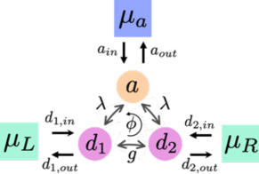
The coherent part of the total Hamiltonian takes the form
| (10) |
Here, () is the annihilation operator for the primary dot (auxiliary dot ), is the corresponding electronic on-site energy for the primary dot (the on-site energy of the auxiliary dot is set at zero, as it plays a negligible role in the large damping limit). () is the coherent coupling between the two primary dots (between primary dots and the auxiliary dot).
To break the symmetry of the two dots, an external magnetic field is applied. As a result, coherent electrons moving in a closed loop pick a phase proportional to the magnetic flux through the loop. The coherent tunneling and therefore become complex. However, in such a closed loop architecture one can always shift the complex phase of into that of . We thus set to be real, and keep complex. We also set the levels to be identical, . This ensures that nonreciprocity emerges here due to the combination of complex coherent coupling and dissipation engineering, and not due to the energetic asymmetry between the dots.
We write down the corresponding HLEs for annihilation operators using Eq. (6) (explicit time dependence is suppressed):
| (11) |
where we have denoted , is the complex conjugate of . In the large damping limit, one can adiabatically solve the last HLE Metelmann and Clerk (2015), yielding
| (12) |
Inserting it into the HLEs for , , we find
| (13) |
with . Note that the coherent coupling involves in the first line of Eq. (III.1) and in the second line. Therefore, the two coupling terms may cancel, but only in one of the above two equations. Here, we set the directionality condition
| (14) |
which results in a nonreciprocal interaction: Dot 2 is driven by dot 1 but not vice versa, as dot 1 is not influenced by dot 2. This directionality can be reversed by tuning the phase of : Let . Considering the opposite loop phase (this can be achieved by reversing the direction of the applied magnetic field), Eq. (14) turns into which is just the condition .
To identify an optimal configuration, we turn to the scattering matrix by utilizing Eqs. (12) and (III.1) (for simplicity, only the elements of the upper left matrix are listed as it corresponds to the scattering matrix for the primary two-dot system):
| (15) |
Intriguingly, one can readily obtain the directionality condition Eq. (14) by setting .
We recall that in the scattering formalism, is the reflection amplitude, of an electron of energy to arrive towards dot 1 from lead , and be scattered back to that same electrode. Similarly, is the transmission amplitude, for an incoming electron from the side to be absorbed at dot 1, and be transmitted to the terminal through dot 2. The directionality condition requires , yet allows the reverse transmission process, .
Applying the directionality condition, the scattering matrix elements reduces to ()
| (16) |
We can further suppress reflections, that is diagonal elements of the scattering matrix. In the resonance limit (i.e., ), one immediately finds that when tuning
| (17) |
In analogy to quantum optomechanical systems, we refer to this latter relation as an impedance matching condition. Notably, this condition cannot be inferred from the HLEs Eq. (III.1).
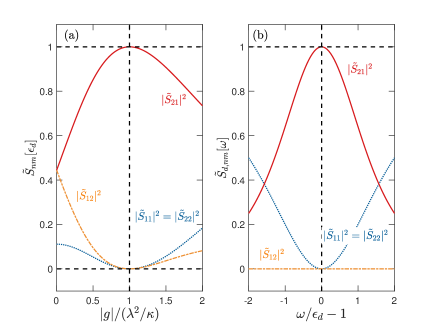
We point out that when Eq. (17) holds, which corresponds to a maximum nonreciprocity between the two primary dots. However, this maximum nonreciprocity only occurs for resonant situation, with , while the directionality condition Eq. (14) holds for all frequencies. The behavior of scattering matrix elements as functions of the tunneling element and the frequency is depicted in Fig. 2, from which we clearly observe the optimal conditions, as well as parameter ranges where an efficient nonreciprocal interaction can be achieved. The directionality condition is analyzed in panel a. In panel b, the directionality condition is satisfied, and we test the resonance condition, which is required for impedance matching.
III.2 Four-dot system: Indirect coherent coupling between primary dots
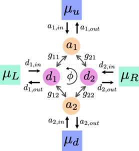
We now turn to the situation in which the primary dots are not directly connected. To this end, we consider a four-dot system as shown in Fig. 4, a minimal model that consists two primary dots and two auxiliary dots. The coherent part of the total Hamiltonian in Eq. (1) reads
| (18) | |||||
where () is the annihilation operator for the primary dot (auxiliary dot ), () is the corresponding electronic on-site energy for primary dot (auxiliary dot ), are the coherent hopping rates between primary and auxiliary dots. We again set . Here, the on-site energies for auxiliary dots are important, in particular, we will see below that one needs to set so as to ensure the directionality condition to be fulfilled, similar to the situation in quantum optomechanical systems Bernier et al. (2017); Peterson et al. (2017).
To determine optimal conditions for nonreciprocal interaction, we again resort to the HLEs for annihilation operators by using Eq. (6) together with Eq. (18),
| (19) |
In the large damping limit in which defines the largest energy scale, one can adiabatically solve HLEs for auxiliary operators, yielding
| (20) |
Inserting them into the HLEs for , , we find
| (21) | |||||
here, we have denoted and .
A nonreciprocal interaction between the two primary dots is achieved by letting while keeping finite, that is, we consider a situation in which primary dot 2 is influenced by primary dot 1 but not vice versa. Without loss of generality, we take all hopping rates to be real except with a loop phase , . To clarify the analytical results, we further assume that each auxiliary dot is equally coupled to both primary dots such that and . Hence the directionality requirement corresponds to the following loop phase
| (22) |
As can be seen, nonreciprocal interaction is absent if since then is a real number and both and vanish. Similar to the three-dot case, we can reverse the direction of the nonreciprocal interaction at the opposite loop phase.
To gain more insights into the optimal configuration, we examine the scattering matrix obtained from Eqs. (III.2) and (III.2) in the Fourier space (for simplicity, only the elements of the upper left matrix are listed as it corresponds to the scattering matrix for the primary two-dot system by choosing the basis order , , , ):
| (23) |
where we have denoted , . We readily obtain the directionality condition Eq. (22) by letting .
Considering the on-resonance situation with and impedance matching the system with or equivalently
| (24) |
we obtain the following scattering matrix elements
| (25) |
under the directionality condition [cf. Eq. (22)]. The expression for further highlights the necessity of for the appearance of nonreciprocal interactions as when the directionality condition is fulfilled.
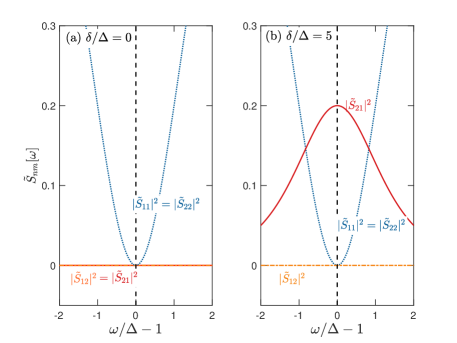
The behavior of the scattering matrix elements as a function of frequency is depicted in Fig. 4. In the calculation, we choose , such that when the directionality condition is applied. In Fig. 4 (a), we show that there is simply no tunneling between two primary dots when ; the transmissions indicate that electrons from primary dots are all absorbed by auxiliary dots. Trivially, there is also no nonreciprocity in this case. When as depicted in Fig. 4 (b), we can achieve nonreciprocity. However, we should point out that here the scattering matrix cannot be optimized to the ideal case in which , in contrast to the three-dot system. In principle. approaches 1 when , but this is at odds with our assumption that corresponds to the largest energy scale in the problem.
IV Nonequilibrium charge transport
So far, we discussed nonreciprocity for charge transport by studying the properties of the scattering matrix, with as the energy of an incoming electron, [see Eq. (9)]. However, unlike in optomechanical systems, where it is sufficient to analyze the behavior at a particular frequency Metelmann and Clerk (2015), for electron transport the observable is the electrical current, integrated over electron transmission within the bias window. While the directionality condition does not depend on frequency, impedance matching relies on the resonance condition to eliminate reflections, see the discussion of Eq. (17). As such, it is clear that we cannot exactly satisfy the zero reflection condition for the net charge current, and it is important to analyze the extent of nonreciprocity in the behavior of the current at finite bias voltage.
In this Section, we analyze signatures of nonreciprocal interaction from the perspective of charge transport, when chemical potentials of the attached primary leads are tuned to be different. We require that chemical potentials of auxiliary leads are much smaller than those of primary leads so as to ensure that electrons and noise from the auxiliary leads do not transmit to the primary system, a feature favored by quantum signal processing applications. We adopt a convention that forward voltage bias corresponds to . As such, nonreciprocity for charge current corresponds to observing (), that is, the current towards the left metal (from the right electrode, since the auxiliary electrodes cannot feed in electrons) in the reverse (negative) bias regime is different from the current reaching the right electrode from the left one in the forward bias regime.
Observables of interests are the steady state charge currents out of left (L) and right (R) lead (see Figs. 1 and 3 for illustrations). In the context of GIOM, they have the following formally-exact definitions in the Heisenberg picture Liu and Segal (2020a) (it is sufficient to work with input fields due to input-output relations Eq. (II))
| (26) |
Here, “Im” refers to an imaginary part, the ensemble averages are performed with respect to an initial factorized state for dots and leads. Specifically, we assume that the metallic leads are initially in their thermal equilibrium states characterized by the Fermi-Dirac distribution with the corresponding chemical potential and the temperature. With the initial thermal equilibrium states, statistics for input fields can be defined (see appendix A for details). As the GIOM conserves the total charge in the metal-dots system Liu and Segal (2020a), the current flowing into the auxiliary leads can be inferred from charge conservation.
Unless otherwise stated, we assume in the following charge current calculations that the system has been tuned to satisfy both the directionality condition and the impedance matching condition [cf. Eqs. (14) and (17) for the three-dot system, Eqs. (22) and (24) for the four-dot system].
IV.1 Three-dot system
To obtain steady state charge currents for the three-dot system, we should first solve Eq. (III.1) in the steady state limit, and then insert those solutions into definitions Eq. (IV). A straightforward evaluation leads to (details can be found in appendix B)
| (27) | |||||
| (28) | |||||
As can be seen, is independent of the right lead influence due to the nonreciprocal interaction. On the contrary, has contributions from both the left lead and the auxiliary reservoir. Noting that we consider the parameter regime of , which ensures that no electrons as well as noise from the auxiliary reservoir transmit to the system. Therefore, according to Eqs. (27) and (28), is always positive (electron leave the lead), irrespective of the direction of voltage bias between the two primary dots, while can become negative, thereby allowing electrons from the left lead to reach into the right one.
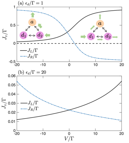
The behavior of the steady state charge currents, and , are shown in Fig. 5. We consider both resonant and off-resonant regimes, noting that the impedance matching condition, Eq. (17) relies on resonant transport behavior (see also Fig. 2 (b)). As can be seen from the Fig. 5 (a) for the resonant transport case, in the negative bias regime with , electrons out of the right lead are routed into the auxiliary dot without flowing into the left lead (otherwise should become negative). While in the case of forward (positive) bias, electrons out of the left lead follow two transport pathways: One part is transmitted into the right lead and the other part is absorbed by the auxiliary dot. The corresponding electron transfer pathways in the reverse and forward bias regimes are highlighted in the insets of Fig. 5 (a). Overall, the intrinsic dissipation of the auxiliary dot, which takes electrons out of the system regardless of the transmission direction, is an essential ingredient for the nonreciprocal interaction engineering reported here. This figure illustrates one of the main results of this work, that we observe nonreciprocity for the integrated charge current, not just the scattering matrix: At high positive voltage, current flows from the left to the right lead. However, there is no net current from the right metal to the left one when we reverse the voltage bias, .
In Fig. 5 (b), we further consider the off-resonant charge transport case. In this regime, the second term on the right-hand-side (RHS) of Eq. (28) becomes negligible compared to the first term, hence and become symmetric under the transformation , thereby indicating that there is no nonreciprocal behavior between the two primary dots: Injected electrons from both sides are all absorbed by the auxiliary dot towards its reservoirs. Those features are clearly visible from Fig. 5 (b): Both and are positive in the whole voltage bias regime and become almost symmetric about .

Clearly, the directionality condition is the basis for nonreciprocal interactions. To highlight that the impedance matching condition Eq. (17) is also crucial in nonreciprocal interaction engineering, we show resonant charge current results without imposing the condition (17) in Fig. 6, based on the following general expressions [cf. Eqs. (B3) and (B12) in Appendix B]:
Here, we have introduced the dimensionless ratio . Compared with Eqs. (27) and (28), we note that the transmission functions are modified when , but that the overall transport trends are the same. Hence, we still have a nonreciprocal behavior as can be seen from this figure, but the contrast between the forward and reverse bias regimes becomes less and less significant as increases. Particularly, the small magnitude of for in the forward regime indicates that one needs relatively large voltage values to efficiently pump electron from the left to the right lead against reflection at the primary dot 1.
For comparison, it is also useful to explore charge transport behavior with reciprocal couplings, that is, from the perspective of coherent transport as the whole subsystem (primary and auxiliary dots) described by is fully coherent. Noticing that the charge current obtained from the GIOM is equivalent to that of the Landauer-Büttiker (LB) theory in the coherent limit Liu and Segal (2020a), we can also directly adopt the multiterminal LB expression Landauer (1957); Büttiker (1988) for charge current:
| (30) |
where the transmission functions with the dot-lead coupling matrix, , here is the matrix form for with a loop phase . is the identity matrix.
For the three-dot system, we have , and and
| (31) |
A direct calculation leads to
here, . Interestingly, one can infer the directionality condition Eq. (14) by letting in the large damping limit of . As a comparison, we should point out that it is impossible to engineer a directionality in a two-dot system from the LB expression as we always have , thereby highlighting the important role of a damped auxiliary dot in engineering nonreciprocal interactions.
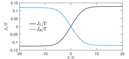
In Fig. 7 we present the charge current when , which leads to and thus to reciprocal tunneling in Eq. (III.1). Calculations are done with the LB expression [cf. Eq. (30) together with Eq. (IV.1)]. It is evident that the nonreciprocal behavior is absent, with , as compared to Fig. 5 (a). Interestingly, we note that the charge currents in the present case, without directionality condition, are about one order of magnitude smaller than currents in the optimal configuration shown in Fig. 5 (a). This is because the latter is built upon a single dot transmission function, , and its square according to Eqs. (27) and (28). Hence the nonreciprocal interaction engineering not only induce unidirectional transport, but also enhances the magnitudes of charge currents.
IV.2 Four-dot system
We now turn to demonstrate that the charge current in a nonequilibrium four-dot system also demonstrates nonreciprocity. For simplicity, we take , in the following. Steady state charge currents for the four-dot system can be obtained in a similar manner as in the three-dot case (details can be found in Appendix C)
| (33) | |||||
Note that if we take , and become symmetric with , implying the absence of nonreciprocal interactions as we pointed out in Sec. III.2.
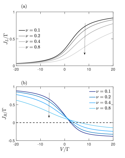
The behavior of the charge currents based on Eqs. (33) and (LABEL:eq:JR_fd) is shown in Fig. 8. In the calculations, we consider the parameter regime of , which ensures that electrons from the auxiliary reservoir do not enter the system. Therefore, is always positive (current flows outside) irrespective of the direction of voltage bias between the two primary dots. On the contrary, can become negative.
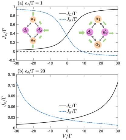
It is evident that qualitative features of Fig. 8 are similar to those of Fig. 5 for the three-dot system: In the resonant transport regime as shown in Fig. 8 (a), electrons leaving the right lead are routed into the auxiliary dots, and electrons do not flow into the left lead in the reverse bias regime with . While in the case of forward (positive) bias, the charge current out of the left lead can flow into the right electrode. However, due to the presence of two auxiliary dots, only a small fraction of the electrons can be transmitted into the right lead, which is in accordance with the fact that cannot reach the maximum value 1 in this setup. In the off-resonant transport regime, depicted in Fig. 8 (b), nonreciprocal transport is largely suppressed as the negative contributions on the RHS of Eq. (LABEL:eq:JR_fd) become negligible and the first two terms on the RHS prevail. This makes almost symmetric, .
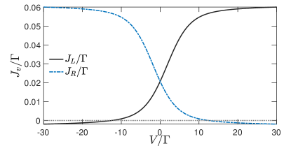
For comparison, we study the charge current with real-valued tunneling elements based on Eq. (30). For the sake of simplicity, the transmission functions are given in Appendix D. Results for and are shown in Fig. 9, illustrating reciprocity.
Similar to the three-dot system, charge currents in a fully-coherent setup are one order of magnitude smaller than those in optimal configuration shown in Fig. 8 (a). The disparity results from the fact that the latter [cf. Eqs. (33) and (LABEL:eq:JR_fd)] involves only single dot transmission function and its square, which are more efficient in charge transport than those for an intrinsic four-dot system as listed in appendix D. Hence, we further confirm that nonreciprocal interaction engineering not only induce unidirectional transport, but also enhance the magnitude of charge currents.
V Electron-phonon coupling and nonreciprocity
So far, we only considered engineering nonreciprocal interaction in noninteracting electron systems. For the purpose of applications, it is crucial to investigate whether the so-obtained nonreciprocal behavior persists in the presence of many-body interactions such as electron-phonon couplings. To this end, we take the three-dot system as an example. The coherent Hamiltonian in Eq. (10) is extended to comprise collections of phonons with electron-phonon couplings,
| (35) | |||||
Recall that counts primary dots and that the index corresponds to the auxiliary dot. We assume that all dots are coupled to their local phonon environment. Here, local phonons with frequencies () are described by bosonic annihilation operators ; electron-phonon couplings are measured by dimensionless coupling strengths, . The influence of each phonon bath, acting on electrons, is characterized by the spectral density function . For simplicity, we assume that the three dots have the same phonon spectral density, that is, . Without loss of generality, we adopt an Ohmic spectrum with a dimensionless electron-phonon coupling strength and the cut-off frequency of the phonon bath.
To handle potentially strong electron-phonon couplings, we perform the small polaron transformation with the unitary operator and displacement operators ()
| (36) |
The transformed Hamiltonian then reads
| (37) | |||||
As can be seen, the transformation amounts to the renormalization of on-site energies, with , and to the dressing of tunneling elements. In the above expressions, we introduced the polaron operators as
| (38) |
In the polaron frame, the input-output relation, Eq. (5), is modified as follows Liu and Segal (2020a)
| (39) |
Recall that (), , and that .
To obtain HLEs for electronic operators in the polaron frame, we replace the coherent Hamiltonian by in Eq. (6) Liu and Segal (2020a), yielding
| (40) |
In the large damping limit, we adiabatically solve the last HLE,
| (41) |
where we have approximated as . Inserting it into the HLEs for , , we find
| (42) | |||||
As can be seen, one can obtain perfect directionality by setting
| (43) |
which is precisely the directionality condition identified for a noninteracting three-dot system [cf. Eq. (14)]. Hence, nonreciprocity can be achieved in the presence of local electron-phonon couplings, and the directionality condition is identical with and without this interaction.
Next, we turn to the scattering matrix in the presence of electron-phonon couplings and study whether the impedance matching condition, Eq. (17), holds. As the drift matrix and the coefficient matrix in Eq. (8) become time-dependent, the previous definition for the scattering matrix is no longer applicable. However, we now show that diagonal reflection elements and can still be identified, allowing to enforce an impedance matching condition. As a comment, we note that phonon scattering effects influence transport from dot 1 to dot 2, thus we cannot identify a single-frequency transmission element .
In parallel to polaron operators defined in Eq. (38), we introduce the polaron-dressed input/output fields ()
| (44) |
and rewrite the input-output relation Eq. (39) as
| (45) |
We are thus seeking to understand the scattering of incoming polarons (phonon-dressed electrons) in the setup.
We can now proceed precisely as we did through Eqs. (8)- (9). We formally write down (V) as follows,
| (46) |
where the matrix generally depends on the bosonic-bath operators. However, the equation of motion for , Eq. (V), does not depend on , thus . In frequency domain (with ‘’ as Fourier’s transform) we write
| (47) | |||||
Together with Eq. (45), which connects the input and output fields on site ‘1’, we identify the reflection element as
| (48) |
Next, shifting attention to the EOM for , we note that depends on bosonic operators (thus on time), leading to a convolution in the frequency domain, corresponding to phonon scattering processes. In Fourier’s space we write
| (49) | |||||
without explicitly writing down the last two terms. Specifically, due to the directionality condition the last term does not depend on the input field . Thus, together with Eq. (45), one can readily extract , and further find that .
Eq. (48) takes the same form as Eq. (III.1), except that the electronic energy is renormalized by electron-phonon couplings, that is, . Hence, we recovered the impedance condition Eq. (17) with .
Altogether, while the transport towards electrode ‘2’ involves phonon scatterings, importantly, diagonal elements of the scattering matrix do not depend on bosonic operators, and hence are time-independent. We found that both directionality and impedance matching conditions [cf. Eqs. (14) and (17) ] identified in the noninteracting electron scenario survived in the presence of local electron-phonon couplings. This nontrivial observation is another central result of our work.
Although with local electron-phonon couplings we retrieved the same optimal conditions for nonreciprocal interactions as in the noninteracting case, electron-phonon interactions suerly affect transport of electrons (noting the off-diagonal elements of involve convolutions between displacement operators and electronic ones) and consequently the charge current, which is given by (details can be found in Appendix E),
| (50) | |||||
Here, we introduced a generalized transmission function, with the phonon correlation function . As can be seen, Eqs. (27) and (28) are recovered in the noninteracting limit where .
In Fig. 10, we show results for with varying the dimensionless electron-phonon coupling strength . Compared to Fig. 5 (a), we see that the presence of electron-phonon coupling suppresses the nonreciprocal behavior in electron transport: The magnitudes of and depict a monotonic decreasing trend as a function of in the whole voltage regime, in accordance with previous findings Liu and Segal (2020a). Particularly, the contrast between and reduces with increasing .
VI Summary
In this work, we developed an input-output scheme, which allows for exploring nonreciprocal interactions in electronic, quantum dot systems based on their quantum optomechanical analogs. In particular, Heisenberg-Langevin equations for electronic operators provide a natural definition for the scattering matrix, relating input and output fields from the metallic leads. With this theoretical advance, we constructed nonreciprocity through dissipation-engineering by utilizing auxiliary damped dots and identifying optimal conditions for nonreciprocal interaction in a straightforward manner.
For illustrations, we considered minimal multiterminal quantum dot models, which can serve as building blocks for larger networks. In the noninteracting electron scenario, we identified directionality condition as well as the so-called impedance matching condition under which optimal nonreciprocal behaviors emerged. We further showed unidirectional charge transport in the optimal regime for nonequilibrium settings, hence one can build quantum diodes by utilizing nonreciprocal interactions. We also demonstrated that electron-phonon couplings preserve optimal conditions. As we considered metallic leads as well as solid-state quantum dot architecture, our proposal can be realized and verified by state-of-the-art experimental techniques.
In summary, the main contributions of this work for nonreciprocal electronic devices are: (i) The GIOM formalism can be conveniently adopted to identify conditions for nonreicprocity at the level of the scattering matrix. (ii) The electrical current, which integrates electrons in the bias window, maintains signatures of nonreciprocity in the resonant tunneling regime. (ii) Local electron-phonon couplings preserve nonreciprocal conditions, but overall currents are gradually suppressed at strong coupling.
We note that intrinsic dissipation of auxiliary dots, which takes electron out of the system regardless of the transmission direction, is an essential ingredient for the nonreciprocal behavior reported here. However, it also reduces transmission efficiency between primary dots as can be seen from the comparison between the four-dot system and the three-dot counterpart, thereby making the use of the proposed dissipation engineering in large quantum dot networks inefficient. Further improvements are required, and we leave them to future works.
Acknowledgements.
The authors acknowledge support from the Natural Sciences and Engineering Research Council (NSERC) of Canada Discovery Grant and the Canada Research Chairs Program.Appendix A Statistics for input fields
As the input fields depend only on initial conditions, see Eq. (3), we easily identify the following anticommutation relations
| (A1a) | ||||
| (A1b) | ||||
and the following correlation functions for input fields
| (A2) |
Here, when for the two primary dots, for the three-dot system and for the four-dot system, is the Fermi-Dirac distribution with temperature and chemical potential .
Appendix B Evaluating charge currents for the three-dot system
To get the steady state charge currents, we solve Eq. (III.1) under the directionality condition, Eq. (14) with the following stationary solutions for in the limit of :
| (B1) | |||||
We first focus on as does not depend on . Utilizing the correlation functions for input fields listed in appendix A, the involved ensemble averages in [see definition in Eq. (IV)] can be evaluated as
| (B2) |
Inserting them into the definition of , we find
| (B3) |
Eq. (27) of the main text is recovered by imposing the impedance matching condition .
For , we first have,
| (B4) |
For the average occupation number, we find
| (B5) | |||||
The first two terms on the RHS of Eq. (B5) can be simplified as
| (B6) |
For the third term on the RHS, we find
| (B7) |
by noting
| (B8) |
The last two terms on the RHS give
| (B9) |
as
| (B10) |
Putting those terms together we get
| (B11) |
Inserting Eqs. (B4) and (B11) into the definition of , we find the following expression
| (B12) | |||||
After the impedance matching condition, , we recover Eq. (28) in the main text.
Appendix C Evaluating charge currents for the four-dot system
Under the directionality condition, (14), and the impedance matching condition (17), we solve Eq. (III.2) in the steady state limit,
| (C1) | |||||
We first focus on as does not depend on . By noting the correlation functions for input fields listed in appendix A, the involved ensemble averages in [see definition in Eq. (IV)] can be evaluated as
| (C2) |
Inserting them into the definition of we recover Eq. (33) in the main text by noting .
For , we first have
| (C3) |
For the average occupation number, we find
| (C4) | |||||
The first three terms on the RHS of Eq. (C4) can be simplified as
| (C5) |
For the fourth term on the RHS of Eq. (C4), we find
| (C6) |
by noting
| (C7) |
The last four terms on the RHS of Eq. (C4) give
| (C8) |
by using the following correlation functions
| (C9) |
Inserting and into the definition, we recover Eq. (LABEL:eq:JR_fd) in the main text under the impedance matching condition .
Appendix D Transmission functions for the four-dot system
We organize primary and auxiliary dots in the following order, . The dot-lead coupling matrices read , , and . The matrix form for the coherent Hamiltonian takes the following form
| (D1) |
A direct calculation leads to:
| (D2) |
Appendix E Evaluating charge currents for the three-dot system in the presence of electron-phonon couplings
In the polaron frame, the charge current definitions are modified as Liu and Segal (2020a)
| (E1) |
To get the steady state charge currents, we solve Eq. (V) under the directionality condition (14) and the impedance matching condition (17) in the limit of :
| (E2) | |||||
Similar to appendix B, we first evaluate ensemble averages involved in ,
| (E3) | |||||
In the second line, we have decoupled electron and phonon correlations, a common approximation in the polaron frame Liu and Segal (2020a); Galperin et al. (2006); Maier et al. (2011); Seoane Souto et al. (2015), which relies on this coupling to be moderate,
| (E4) |
Here, we introduced the phonon correlation function ; note that we neglect the dot subscript since the phonon environments are assumed to have identical spectral density functions, for the sake of simplicity. By assuming an initial thermal equilibrium state for the phonon environments, we recover the standard form
| (E5) |
Similarly, we find
| (E6) | |||||
Here, “Re” refers to the real part. Inserting them into the definition of , we find
| (E7) |
We note that Eq. (27) in the main text is recovered when , namely, in the coherent limit of noninteracting electrons.
As for ensemble averages involved in , we follow similar procedures and find
| (E8) |
and
| (E9) | |||||
Consequently, we get the following expression for :
| (E10) | |||||
The noninteracting expression, Eq. (28) in the main text is recovered when .
References
- Hafezi and Rabl (2012) M. Hafezi and P. Rabl, “Optomechanically induced non-reciprocity in microring resonators,” Opt. Express 20, 7672–7684 (2012).
- Ranzani and Aumentado (2014) L. Ranzani and J. Aumentado, “A geometric description of nonreciprocity in coupled two-mode systems,” New J. Phys. 16, 103027 (2014).
- Ranzani and Aumentado (2015) L. Ranzani and J. Aumentado, “Graph-based analysis of nonreciprocity in coupled-mode systems,” New J. Phys. 17, 023024 (2015).
- Metelmann and Clerk (2015) A. Metelmann and A. A. Clerk, “Nonreciprocal photon transmission and amplification via reservoir engineering,” Phys. Rev. X 5, 021025 (2015).
- Ruesink et al. (2016) F. Ruesink, M. Miri, A. Al , and E. Verhagen, “Nonreciprocity and magnetic-free isolation based on optomechanical interactions,” Nat. Commun. 7, 13662 (2016).
- Xu et al. (2016) X. Xu, Y. Li, A. Chen, and Y. Liu, “Nonreciprocal conversion between microwave and optical photons in electro-optomechanical systems,” Phys. Rev. A 93, 023827 (2016).
- Xu et al. (2017a) X. Xu, A. Chen, Y. Li, and Y. Liu, “Single-photon nonreciprocal transport in one-dimensional coupled-resonator waveguides,” Phys. Rev. A 95, 063808 (2017a).
- Xu et al. (2017b) X. Xu, A. Chen, Y. Li, and Y. Liu, “Nonreciprocal single-photon frequency converter via multiple semi-infinite coupled-resonator waveguides,” Phys. Rev. A 96, 053853 (2017b).
- Shen et al. (2016) Z. Shen, Y. Zhang, Y. Chen, C. Zou, Y. Xiao, X. Zou, F. Sun, G. Guo, and C. Dong, “Experimental realization of optomechanically induced non-reciprocity,” Nat. Photonics 10, 657–661 (2016).
- Bernier et al. (2017) N. R. Bernier, L. D. T th, A. Koottandavida, M. A. Ioannou, D. Malz, A. Nunnenkamp, A. K. Feofanov, and T. J. Kippenberg, “Nonreciprocal reconfigurable microwave optomechanical circuit,” Nat. Commun. 8, 604 (2017).
- Peterson et al. (2017) G. A. Peterson, F. Lecocq, K. Cicak, R. W. Simmonds, J. Aumentado, and J. D. Teufel, “Demonstration of efficient nonreciprocity in a microwave optomechanical circuit,” Phys. Rev. X 7, 031001 (2017).
- Fang et al. (2017) K. Fang, J. Luo, A. Metelmann, M. H. Matheny, F. Marquardt, A. A. Clerk, and O. Painter, “Generalized non-reciprocity in an optomechanical circuit via synthetic magnetism and reservoir engineering,” Nat. Phys. 13, 465–471 (2017).
- Barzanjeh et al. (2018) S. Barzanjeh, M. Aquilina, and A. Xuereb, “Manipulating the flow of thermal noise in quantum devices,” Phys. Rev. Lett. 120, 060601 (2018).
- Malz et al. (2018) D. Malz, L. D. Tóth, N. R. Bernier, A. K. Feofanov, T. J. Kippenberg, and A. Nunnenkamp, “Quantum-limited directional amplifiers with optomechanics,” Phys. Rev. Lett. 120, 023601 (2018).
- Xu et al. (2019) H. Xu, L. Jiang, A. A. Clerk, and J. G. E. Harris, “Nonreciprocal control and cooling of phonon modes in an optomechanical system,” Nature 568, 65–69 (2019).
- Loss and DiVincenzo (1998) D. Loss and D. P. DiVincenzo, “Quantum computation with quantum dots,” Phys. Rev. A 57, 120–126 (1998).
- Devoret and Schoelkopf (2013) M. H. Devoret and R. J. Schoelkopf, “Superconducting circuits for quantum information: An outlook,” Science 339, 1169–1174 (2013).
- Malz and Nunnenkamp (2018) D. Malz and A. Nunnenkamp, “Current rectification in a double quantum dot through fermionic reservoir engineering,” Phys. Rev. B 97, 165308 (2018).
- Liu and Segal (2020a) Junjie Liu and Dvira Segal, “Generalized input-output method to quantum transport junctions. i. general formulation,” Phys. Rev. B 101, 155406 (2020a).
- Liu and Segal (2020b) Junjie Liu and Dvira Segal, “Generalized input-output method to quantum transport junctions. ii. applications,” Phys. Rev. B 101, 155407 (2020b).
- Mascarenhas et al. (2019) E. Mascarenhas, F. Damanet, S. Flannigan, L. Tagliacozzo, A. J. Daley, J. Goold, and I. de Vega, “Nonreciprocal quantum transport at junctions of structured leads,” Phys. Rev. B 99, 245134 (2019).
- Damanet et al. (2019) F. Damanet, E. Mascarenhas, D. Pekker, and A. J. Daley, “Controlling quantum transport via dissipation engineering,” Phys. Rev. Lett. 123, 180402 (2019).
- Wingreen et al. (1989) N. S. Wingreen, K. W. Jacobsen, and J. W. Wilkins, “Inelastic scattering in resonant tunneling,” Phys. Rev. B 40, 11834 (1989).
- Carmichael (1993) H. J. Carmichael, “Quantum trajectory theory for cascaded open systems,” Phys. Rev. Lett. 70, 2273–2276 (1993).
- Gardiner (1993) C. W. Gardiner, “Driving a quantum system with the output field from another driven quantum system,” Phys. Rev. Lett. 70, 2269–2272 (1993).
- Landauer (1957) R. Landauer, “Spatial variation of currents and fields due to localized scatterers in metallic conduction,” IBM J. Res. Dev. 1, 223 (1957).
- Büttiker (1988) M. Büttiker, “Absence of backscattering in the quantum hall effect in multiprobe conductors,” Phys. Rev. B 38, 9375–9389 (1988).
- Galperin et al. (2006) M. Galperin, A. Nitzan, and M. A. Ratner, “Resonant inelastic tunneling in molecular junctions,” Phys. Rev. B 73, 045314 (2006).
- Maier et al. (2011) S. Maier, T. L. Schmidt, and A. Komnik, “Charge transfer statistics of a molecular quantum dot with strong electron-phonon interaction,” Phys. Rev. B 83, 085401 (2011).
- Seoane Souto et al. (2015) R. Seoane Souto, R. Avriller, R. C. Monreal, A. Martín-Rodero, and A. Levy Yeyati, “Transient dynamics and waiting time distribution of molecular junctions in the polaronic regime,” Phys. Rev. B 92, 125435 (2015).