CLAIR: A Contract-based Framework for Developing Resilient CPS Architectures
Abstract
Industrial cyber-infrastructure is normally a multi-layered architecture. The purpose of the layered architecture is to hide complexity and allow independent evolution of the layers. In this paper, we argue that this traditional strict layering results in poor transparency across layers affecting the ability to significantly improve resiliency. We propose a contract-based methodology where components across and within the layers of the cyber-infrastructure are associated with contracts and a light-weight resilience manager. This allows the system to detect faults (contract violation monitored using observers) and react (change contracts dynamically) effectively. It results in (1) improving transparency across layers; helps resiliency, (2) decoupling fault-handling code from application code; helps code maintenance, (3) systematically generate error-free fault-handling code; reduces development time. Using an industrial case study, we demonstrate the proposed methodology.
I Introduction
A key focus of Industrial Cyber-Physical System (iCPS) is to reduce factory downtime by employing a more intelligent distributed system that automatically detects faults and dynamically reconfigures to recover from faults without significantly affecting the normal operations [1, 2]. We refer to such systems as resilient systems.
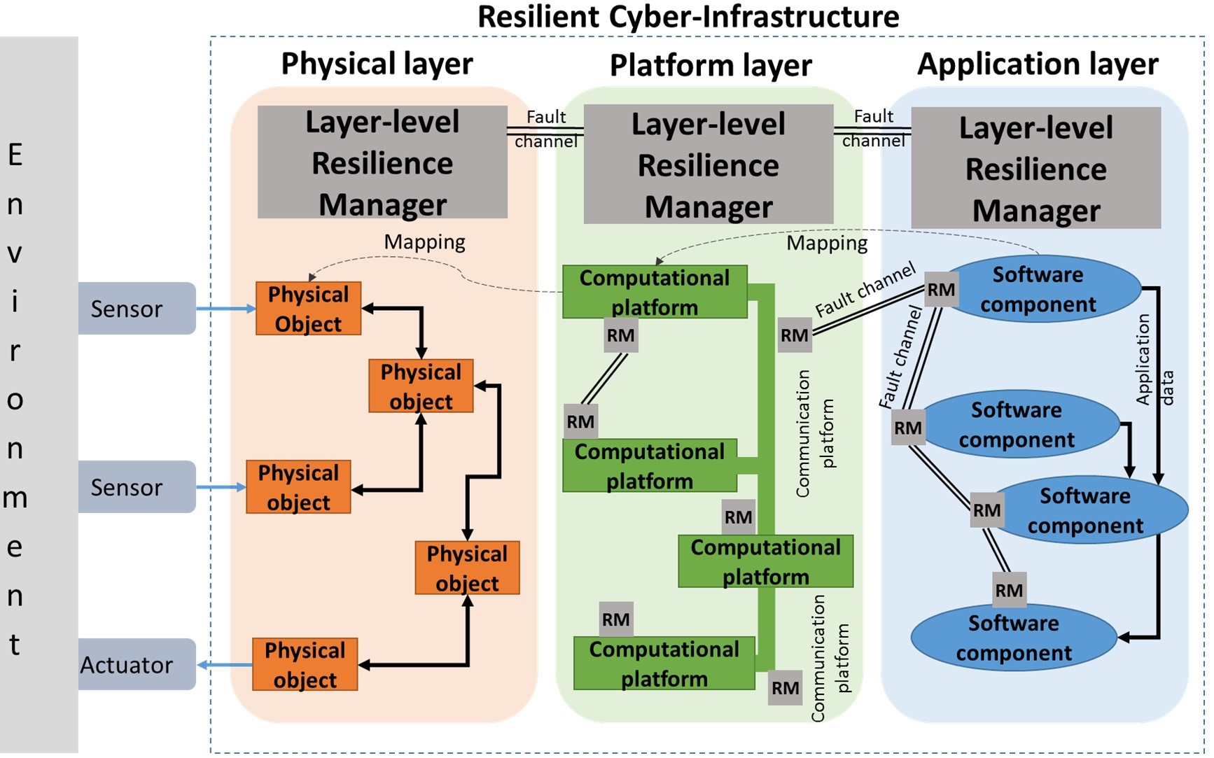
Existing cyber-architecture for Cyber-Physical System (CPS) follows the classical layered middleware with three different layers such as application, platform and physical layers [3], see Figure 1.
(1) The physical layer comprises physical components such as sensors, actuators, controllers and communication hardware.
(2) The platform layer embodies computational and communicational platforms such as operating systems and network managers, respectively.
(3) Finally, the application layer accommodates the software components which describe the behaviour of an application.
In this paper, we focus on the following problems that are applicable across the layers.
Problem 1: Lack of frameworks that enable cross-layer interactions for managing resiliency.
Traditional hardware based redundancy techniques are expensive. In contrast, software based techniques are more affordable and flexible. However, they are not very effective due to the lack of transparency across the layers of the cyber-infrastructure. In the following, we illustrate how cross-layer interactions can improve the quality of resiliency by discussing a few existing resilient architectures. Then, we briefly discuss our framework which enables cross-layer interactions to manage resiliency.
In RIAPS [4] architecture, the focus is on developing a distributed resilient CPS. As an example, a resilient discovery service (DS) was explored. Using heartbeat signals and timestamps, DS detects a failure of a publisher/subscriber pair. When a failure occurs, DS de-registers the pair from the list of registered services. A publisher/subscriber needs to re-register once they become active. The process of de-registering or re-registering is very time consuming and it also needs to be communicated with neighbouring nodes. In this scenario, the cause of the failure (e.g., intermittent fault in the physical layer) and the expected recovery time (e.g. 2 seconds or 2 hours) were not available to the discovery service manager (residing in the platform layer). If the recovery time information was available to the DS manager, it can choose not to de-register a publisher/subscriber and avoid unnecessary time consuming registration process across all neighbouring nodes.
In iLand [5] architecture, the focus is on developing a reconfigurable service oriented distributed system. An application is described as a graph, where each vertex is a service provided by a component of the system. Interestingly, each service may have zero or more alternative services. At runtime, the reconfiguration manger may select an alternative service based on faults. Once again, the reconfiguration manager that is residing in the platform layer is unaware of the fault type or the recovery time. If the platform layer could provide the manager with the list of services that will be affected due to the fault, the manager can select the right order of services in the application graph. This reduces the number of reconfigurations. The paper does not focus on the mechanisms for detecting faults. Also, the architecture design does not discuss any cross-layer interactions to improve resiliency.
For industrial applications based on the IEC 61499 standard [6, 7, 8], an approach to resiliency is provided using a runtime reconfiguration manager [2]. Failure of node executing a publisher is detected by the manger using heartbeats. Then, based on ontology [2, 9], node is identified as an alternative to host the new producer . The new producer is created dynamically and the connection to consumer is modified. Once again, the manager residing in the application layer is unaware of the cause of the node failure. If the platform layer could provide the manager with an expected recovery time, the manager could avoid a time consuming reconfiguration process.
Overall, we believe that there is a need to improve transparency across layers such that they work together to satisfy resiliency needs effectively and at low cost.
Problem 2: Code pollution due to intertwined application code and fault handling code. Managing the increasing functional and safety requirements of industrial automation systems is a daunting process. It results in large amount of code that are hard to understand. The problem is elevated even further as application code is intertwined with fault handling code due to lack of clear guidelines [10]. In typical manufacturing applications, fault handling code on average takes the lion’s share amounting to nearly 83% [10, 11]. Most of this code is manually written and hence error prone, making it harder to certify.
For industrial controllers, a fault isolation methodology is presented using diagnostics automaton that can observe an order/pattern of events that leads to a fault [12]. This approach is prone to the well-known state-explosion problem. Also, it is not expressive enough to describe fault detection techniques based on dynamic models such as Ordinary Differential Equations (ODEs) [13].
Overall, we believe that there is a need for formal approach that systematically decouples fault-handling techniques from application code, and automatically generate fault-handling code with minimal user intervention.
Proposed solution. In our approach, the application and the platform layers are described as a network of components. Components across and within the layers of the cyber-infrastructure are associated with a resilience manger that ensures lightweight fault monitoring and response. We use formal contracts to capture the assumptions on the behaviour of the environment and guarantees about the behaviour of the component [14]. A failure of a contract is treated as a fault. In response to a fault, resilience manager communicates with the resilience managers of other components to find a feasible solution efficiently. E.g., if an object detection component on a conveyor belt of an assembly line is unable to meet its deadline (failure of time-based contract), as a response the resilience manger can switch to a less time consuming detection algorithm or communicate with the motor to temporarily reduce the speed of the conveyor belt.
Overall, the resiliency of the system is managed by two types of resilience managers. (a) A component-level resilience manager (denoted as RM in Figure 1) that is associated to a single component. (b) A layer-level resilience manager (see top of the figure) that is associated to each layer. For the case when a component-level resilience manager is unable to find a feasible solution, it informs the layer-level resilience manger. Our intuition is that at runtime, most of the resiliency issues can be handled by the component-level resilience manager. Finally, fault channels are used for communication between resilience managers. The proposed methodology was briefly introduced earlier [15]. In comparison, this paper presents a more detailed architecture and implementation and validation of the proposed methodology.
The proposed contract-based methodology (CLAIR) for resiliency can be integrated with existing frameworks for designing cyber-infrastructure for CPS such as METROII [16], OpenMETA [17], RIAPS [4] and iLAND [5]. They present complementary features to manage application, resources, devices, logs and security.
Key contributions of the paper:
-
1.
We propose a new contract-based methodology to enable resilient cyber-architecture. Components across and within the layers of the architecture are associated with contracts and a light-weight resilience manager, allowing cross-layer interactions.
-
2.
We use contracts to formally capture the requirements of a component. This allows us to systematically generate observers what are based on computational models such as Finite State Machine (FSM), Timed Automata (TA) and Hybrid Automata (HA). These observers are independent of the application/component behaviour, avoiding code pollution.
-
3.
We implement the architecture using industry standards such as IEC 61499 and Data Distribution Service (DDS). Using an industrial application, we illustrate the features of the proposed contract-based methodology.
II The proposed framework
In the following we discuss some of the non-functional requirements of the proposed architecture and our approach towards implementing them.
1. Cross-layer Interactivity: Allows fine-grained cross-layer communication such that a fault detection and its handling can be implemented across various layers, resulting in a cost-effective and robust cyber-infrastructure. In our approach, component-level resilience manger interacts with components within and across layers. This helps to reduce fault detection and handling time. Furthermore, the layer-level resilience manager provides a more centralised solution for resiliency.
2. Composability: We follow the well know component-based design methodology to ensure functional properties of a component are not influenced by other components. Component behaviour is not altered due to the interactions with other components. Furthermore, system-level properties can be realised from a network of component-level properties [3]. However, non-functional requirements such as timing are hard to guarantee as multiple components of an application layer can be mapped to a single component of a platform layer.
3. Dynamicity:Components are added/removed dynamically. The system should be flexible, self-aware and self-optimise based on the availability of the resources [2]. In our approach, we depend on existing discovery services [4, 18] and the resilience manager to marshal additional resources.
4. Adaptation Quality: Given the limited shared resources and possible conflicting recovery strategies, the system should reason about the quality of adaptations to disturbances [19]. In future, we plan to incorporate a multi-dimensional resilience metric [20] to improve resiliency. The metric needs to be abstract and integrates information across the layers. Also, we need to understand the impact of a failure at component-level on the system-level properties [21].
II-A Overview of a component
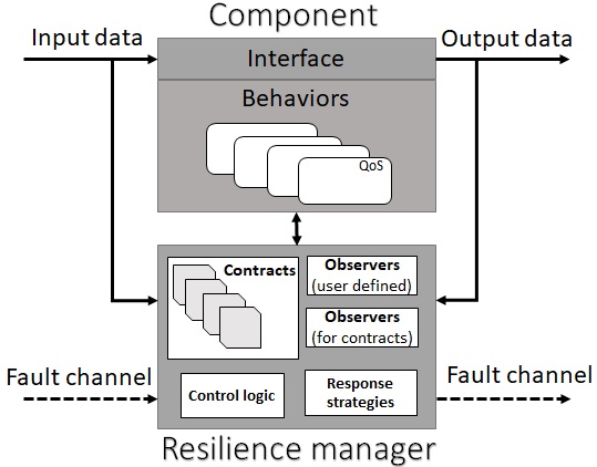
Figure 2 presents an overview of the component and the resilience manager. A component is an open system that (1) receives inputs from the environment, (2) executes a behaviour, and (3) generates output to the environment. The environment could be the collection of other components or the physical world.
-
•
Interface: It defines the Input/Output data channels of a component.
-
•
Behaviours: Multiple behaviours can be defined for a given interface. The resilience manager dynamically selects the behaviour of the component based on requirements.
-
•
Contracts: It clearly captures the assumptions on the behaviour of the environment, and guarantees about the behaviour of the component [14]. At runtime, the resilience manager can switch between contracts to react to the disturbances in the system.
- •
-
•
Resilience manager: Detects faults (using observers) and decides (control logic) the best course of action. It also responds to fault information from other components, via fault channels.
II-B Overview of the design flow
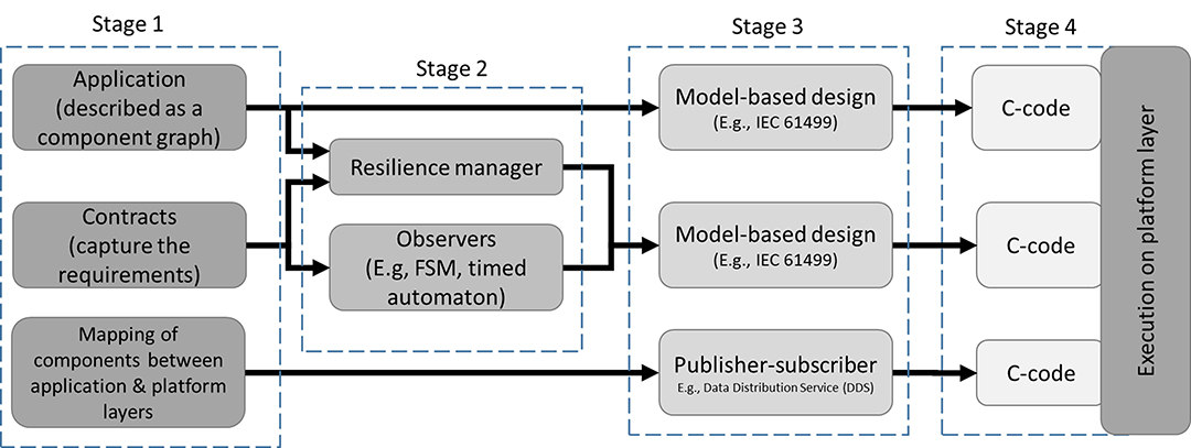
Figure 3 presents an overview of the design flow. In stage 1, (a) an application is described as a component graph, (b) mapping between the components of the application and platform layer is provided and (c) the requirements are captured formally using contracts [14]. In stage 2, observers are generated based on contract specifications. They check the validity of the contracts at runtime. In stage 3, we generate computation and communication models using industry standard such as IEC 61499 and DDS. Finally, in stage 4, using off-the-shelf tools we generate C-code which is executed by the platform layer. For each stage, we now elaborate on our design choices and their advantages.
Stage 1. We have chosen to describe the application as a component graph because component-based software engineering has been successfully used for large-scale system designs. It relies on the concept of developing basic reusable components with well defined interfaces. During integration of components, their well-defined interfaces ensure easy assembly. They are used in popular software tools such as Simulink [27].
Requirements engineering presents a major challenge for software development. Poorly managed and ill-defined requirements lead to lack of visibility into changing requirements and hinders traceability between requirements and implementation. Using contracts [14], we (1) clearly define the requirements, (2) improve visibility due to concise and formal descriptions. More importantly, contracts allow us to systematically decouple fault-detection code from the application code.
Stage 2. Static verification techniques are not generally adequate to validate whether or not the contracts are satisfied. This may be because some of the requirements can only be verified with the data available at runtime (e.g., a sensor producing invalid data). As an alternative, we use observers to monitor the contracts at runtime [22, 24]. To observe static and dynamic behaviour of a system, we express observers using computational models such as finite state machine [23], timed automaton [25, 24] and hybrid automaton [26]. Furthermore, due to the well-defined computation models, the executable code (fault-handling code) can be automatically generated with minimal human intervention. This ensures error-free production ready code.
Stage 3. Since we are targeting industrial automation, we have chosen to implement the application based on the IEC 61499 standard [6, 7, 8]. It uses the component-based engineering to improve software quality and reduce the development time. Importantly, the standard provides a portable high-level executable specification framework for distributed automation. It also allows us to develop reconfigurable applications enabling self-adaptive cyber-physical systems [2].
For communication between the components, we have chosen to use DDS as it enables communication mechanisms that go beyond the classic publish-subscribe model [28, 18]. It can handle the interruptions when a publisher/subscriber is temporarily or permanently unavailable. Furthermore, it allows us to specify QoS parameters over the communication between a publisher and a subscriber.
Stage 4. Finally, we have chosen C language because it is widely supported by many micro-controllers.
III Example application
Figure 4 presents the running example of this paper which reflects a typical assembly line setup in manufacturing. The goal of the application is to successfully identify the work pieces (WP) by their color (red, blue and white) and sort them into their respective storage bins (, and ). The application relies on input from a color sensor (to detect the color of the WP), pulse signal from an encoder (for computing the motor steps), and 3 light sensors to detect the position of a work piece. Also, the application controls the actuators such as the three ejectors (, and ) and a motor.

Given the assembly line is continuously moving and the cyber-infrastructure is distributed, the challenge is to process sensor information and to activate the ejectors at the right time such that the work pieces reach their respective storage bins. Furthermore, the system needs to be resilient to disturbances in the cyber-infrastructure.
III-A Application graph
The assembly line application is described as an application graph. The nodes and edges of the graph represent components and communication between the components, respectively. Figure 4 shows the application graph with seven components . Component periodically samples the pulse signal to count the number of motor steps. The four light barriers () are sampled periodically by Component . Component periodically samples from the colour sensor (). Component computes when an ejector needs to be triggered based on information form the sensors. The three ejectors () are controlled via components . Component controls the speed of the motor (and the conveyor belt). Finally, periodically measures the pressure to detect leaks in the air pressure controlled ejectors.
III-B Mapping from application graph to platform graph
The platform layer comprises of computational platforms () and connecting communication platforms (). The mapping of the components in an application graph to computational platforms is shown in Figure 4. An example of a computation platform is a Linux OS and a communication platform is a software defined network.
Earlier in Section II-A, we described that a component may have multiple behaviours. E.g., component is mapped to the computational platform . Assuming that has three possible behaviours (), based on the platform mapping information we assume that the fixed execution cost can be described using the function . We also assume that the communication between components is handled by an active network infrastructure. Due to the dynamic nature of the network, the communication cost may not be constant. The cost can be described using the function .
III-C Application requirements
Using the constant speed of the conveyor belt we can compute the time taken for a work piece to travel from the first light sensor () to an actuator like ejector , denoted as . We assume that the decomposition of end-to-end timing constraints (e.g., 4 seconds from to ) into deadlines for each component are given. E.g., Component must process the pulse signal within 10ms ().
IV Contract-based fault-detection
In this section, we capture the component-level requirements using contracts based on an existing notation [14].
IV-A Timing requirements
The application component executing on platform node is required to sample the pulse signal every . Furthermore, the time required to process the data should be less than . The requirements are captured using the following contract, denoted as symbol . Symbol denotes that the contract does not make any assumptions/constraints.
IV-B Observers for runtime validation
The contracts are monitored at run-time using observers. In our approach, the observers are expressed using computational models such as finite state machine [23], timed automaton [25, 24] or hybrid automaton [26]. In this section, we illustrate that observers can be generated from the contracts, which capture the requirements.
IV-B1 Timed Automata (TA) as an observer
Timed automata have been successfully used for fault diagnosis of industrial processes [24]. For the running example, the contract specifies the timing requirements on the sampling time of the pulse counter () and the deadline for the processing data (). The observer is implemented using a timed automata [25], see Figure 5.
V Implementation of the Cyber-infrastructure
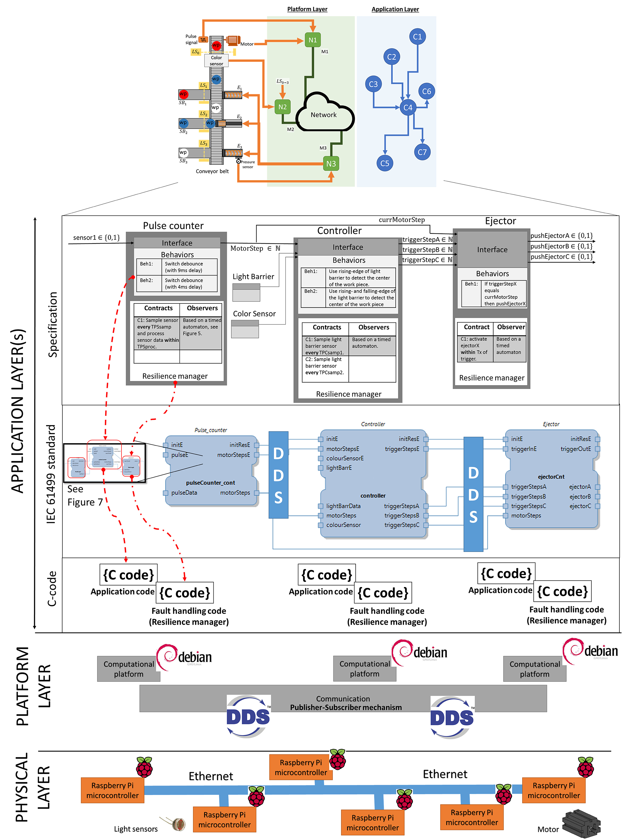
In this section, we present implementation details of the 3-layered cyber infrastructure (see Figure 1) w.r.t. the assembly-line example (see Figure 4). The implementation has an application, platform and physical layers as shown in Figure 6.
V-A Application layer
The application layer accommodates the software components which describe the behaviour of an application. Earlier in Section II-A, we described a component consisting of an interface, behaviours, contracts and observers. Furthermore, an application is specified as a network of components.
V-A1 Component specifications.
An example specification with Pulse counter (Component ), Controller (Component ) and Ejector (Component ) is presented in Figure 6. (a) Interface: The Pulse counter has one sensor input ( or ) which is a rotary encoder connected to a mechanical switch. It has one output MotorStep that represents the movement of the conveyor belt. For example, a work piece takes conveyor-belt steps to move from the first light barrier to the colour sensor. (b) Behaviours: The component Pulse counter has two behaviours to address the noise from the mechanical switch. In Beh1, a delay of ms is used when implementing the de-bounce functionality. In Beh2, the safety margin is reduced such that the delay period is only ms. (c) The contract captures the requirement on the sampling frequency (every ) and the deadline on the processing time (within ). The corresponding observer for monitoring the contract at runtime is modelled using timed automata, see Figure 5. Finally, at runtime the resilience manager switches between behaviours to satisfy the contract. Later in benchmarking, we demonstrate the response of the resilience manager when an observer fails.
V-A2 Translating components to function blocks of IEC 61499 standard.
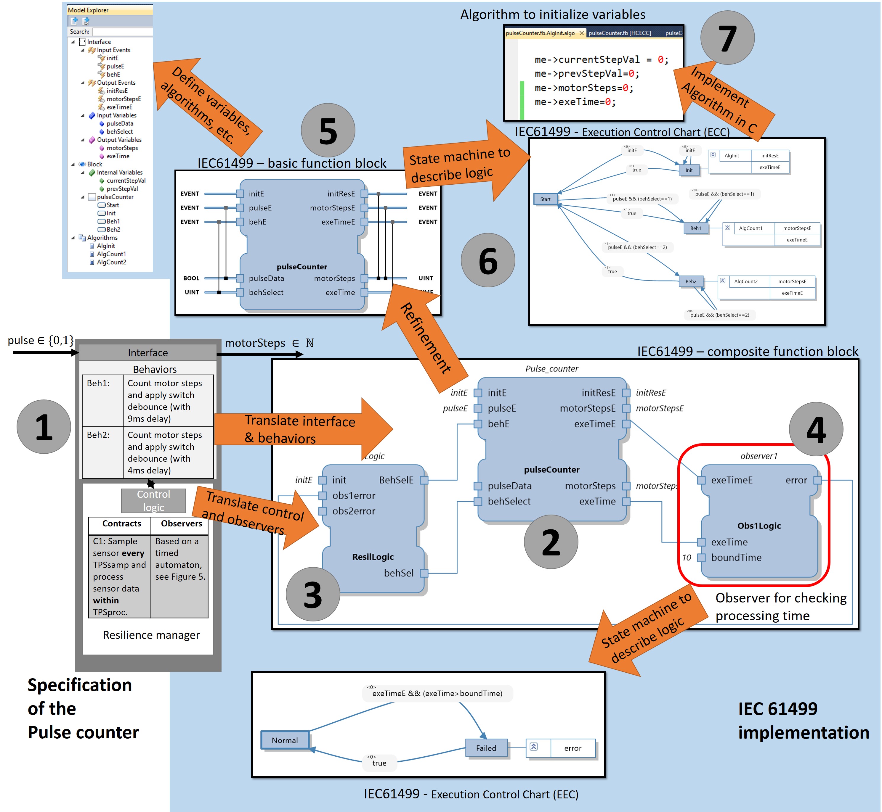
IEC 61499 framework represents a component-based solution for distributed industrial automation systems [29]. An application is described as a network of function blocks, see Figure 7. Given the description of a component (see marker 1, in Figure 7), we present the translation to IEC 61499 standard.
The component’s interface and behaviours are mapped to a basic function block, see marker 2. Due to the event-driven semantics of IEC61499, we need to associate input and outputs with events. E.g., pulse is mapped to the input event pulseE and the input variable pulseData. When the event occurs the associated data is updated internally, see inputs of the block near marker 5. The control logic of the function block is described using an Execution Control Chart (ECC). It receives input events, and according to the current state, executes associated algorithms and emits events. Marker 6 depicts an ECC with 4 states. They are Start, Init, Beh1 and Beh2. When the control reaches the Init state, the associated algorithm AlgInit initialises the internal and output variables (see marker 7). The IEC 61499 standard allows the behaviour to be described using C-language.
The component’s resilience manager consists of a control logic and a set of observers that monitor the contracts. At runtime the resilience manager switches between behaviours (using the behSelect) to satisfy the contracts. An example observer based on timed automata is implemented using a timer, see marker 4. The ECC shows that the observer monitors the time between pulses (pulseE) to ensure that the maximum time between two samples is satisfied () as input to the timer). For more details about the standard and the function blocks, see [29]. Later in the benchmarking section, we demonstrate the response of the resilience manager when an observer fails.
V-A3 Translating IEC 61499 standard to executable C-code
Scheduling of function blocks can be based on either an event-triggered or a cyclic-execution model. Event-triggered scheduling executes a function block when one of the input events are triggered. After execution of the block, the block may emit events which may trigger execution of another blocks. A queuing mechanism is used to address multiple events. FORTE is one such runtime environment which is integrated with 4DIAC IDE [30, 31]. Cyclic execution is an alternative scheduling model which resembles Programmable Logic Controller (PLC) scan cycles. Here all function blocks are executed only once in each cycle. This execution model is supported by an off-the-shelf tool, called ISaGRAF [32]. Both tools depend on a complex runtime environment that is computationally intensive and cannot guarantee a deterministic and a deadlock-free execution. In contrast, a synchronous approach for the execution of function blocks has been developed [29, 23]. It does not require a runtime environment and provides a deterministic and deadlock free code. The tool generated C-code can be easily executed on a micro-controller. This provides flexibility for our implementation as we integrate other technologies such as DDS. Figure 6 shows the generated C-codes for the function blocks.
V-B Platform layer
The platform layer embodies computational and communicational platforms. In figure 6, the generated C-code is executed on a Linux based computational platforms. More specifically, we use Raspbian GNU/Linux 8.0 operating system (kernel version 4.9.35-v7) [33].
Communication across the computational nodes is governed by the networking middle-ware, called, Data Distribution Service (DDS) [28, 18]. DDS enables mechanisms that go beyond the classic publish-subscribe model. It can manage the interruptions when a publisher/subscriber is temporarily or permanently unavailable. Furthermore, it allows us to specify QoS parameters over the communication between a publisher and a subscriber. These parameters can be integrated into the resilience manager using contracts.
V-C Physical layer
All the sensors (light barriers, colour sensor, pulse switch) and actuators (motors, air compressor, ejectors) are part of the development kit from Fischertechnik (product #536633). Most of the computation is performed by the microcontrollers. We have chosen Raspberry Pi 3 due to its flexibility. The processor is a quad core executing at 1.2 GHz and has 1 GB RAM. A major drawback is that it does not support analogue to digital converters. As a cost-effective solution, we used Arduino Pro Mini development board. Ethernet is used for connecting all the Raspberry Pis.
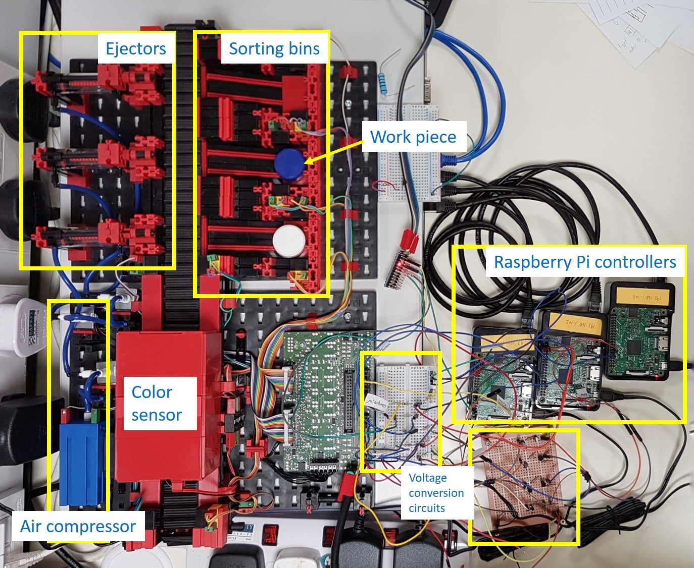
VI An industrial cases study
In this section, we describe the benchmarking process used to validate the proposed contract-based approach. Figure 8 shows an implementation of the assembly line sorting application presented earlier in Figure 4. Using the testbed, we implemented and deployed our resilient cyber-infrastructure and the contract-based approach. In the following, we present two experiments. First, we validate if the end-to-end timing requirement of the application is satisfied. Second, we present a scenario where a resilience manager of a component changes the component’s behaviour when a fault is detected. We observe the fault-detection and recovery times.
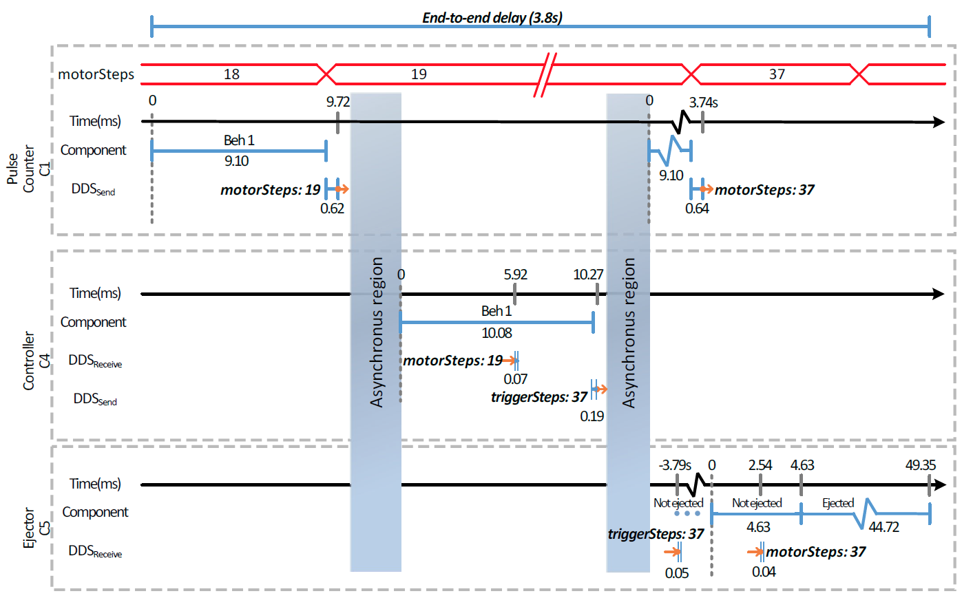
VI-A Experiment 1: validating end-to-end timing constraints
Earlier in Section III-C, we presented that the end-to-end delay of the application should be less than seconds. A failure to meet the deadline may cause a late activation of an ejector. This means a work piece is unable to reach its respective storage bin. In this experiment we validate the implementation by analysing an execution time sequence graph. Figure 9 presents the graph for the three components (Pulse counter, Controller and Ejector) that are of interest. The three components are executing in parallel on three different micro controllers. We observe that the Pulse counter executes its behaviour Beh 1 for a duration of ms. It computes the value of the new MotorSteps as . This information is then published by the DDS. The total duration to compute and send motorSteps is ms. In parallel, Controller receives the data and computes the new value for triggerSteps as . In parallel, Ejector awaits the value of triggerSteps to match the value of current motorSteps which is periodically sent by the Pulse counter. The ejector is then activated to push a work piece from the assembly line. Finally, the measured end-to-end delay of the implementation is seconds which is less than the required seconds.
VI-B Experiment 2: validating the response to a fault
For the Pulse counter (Component ) presented in Figure 9, the execution time sequence graph is presented in Figure 10. The objective of the component is to increment the value of motorStep for every pulse, see the figure. The pulse signal is generated from a mechanical switch (the transient noise is not shown in the figure). To address the noise, a simple denounce algorithm with waiting time of ms and ms is implemented by Beh 1 and Beh 2, respectively. Furthermore, as explained earlier, the deadline for processing the pulse sensor is ms.
During the first two pulses ( to ms) the component does not experience any faults. The contract (deadline of ms) is always satisfied because the execution time of Beh 1 is always less than ms. During the third pulse, a fault occurs in the computational platform which results in longer execution of Beh 1. From the figure, we observe the execution of Beh 1 to be ms due to the fault. This violates the contract after ms. This is also when the architecture detects the fault. The resilience manger decides to change the behaviour of the component from Beh 1 to Beh 2. However, we see the impact on the execution changing only in the fifth pulse.
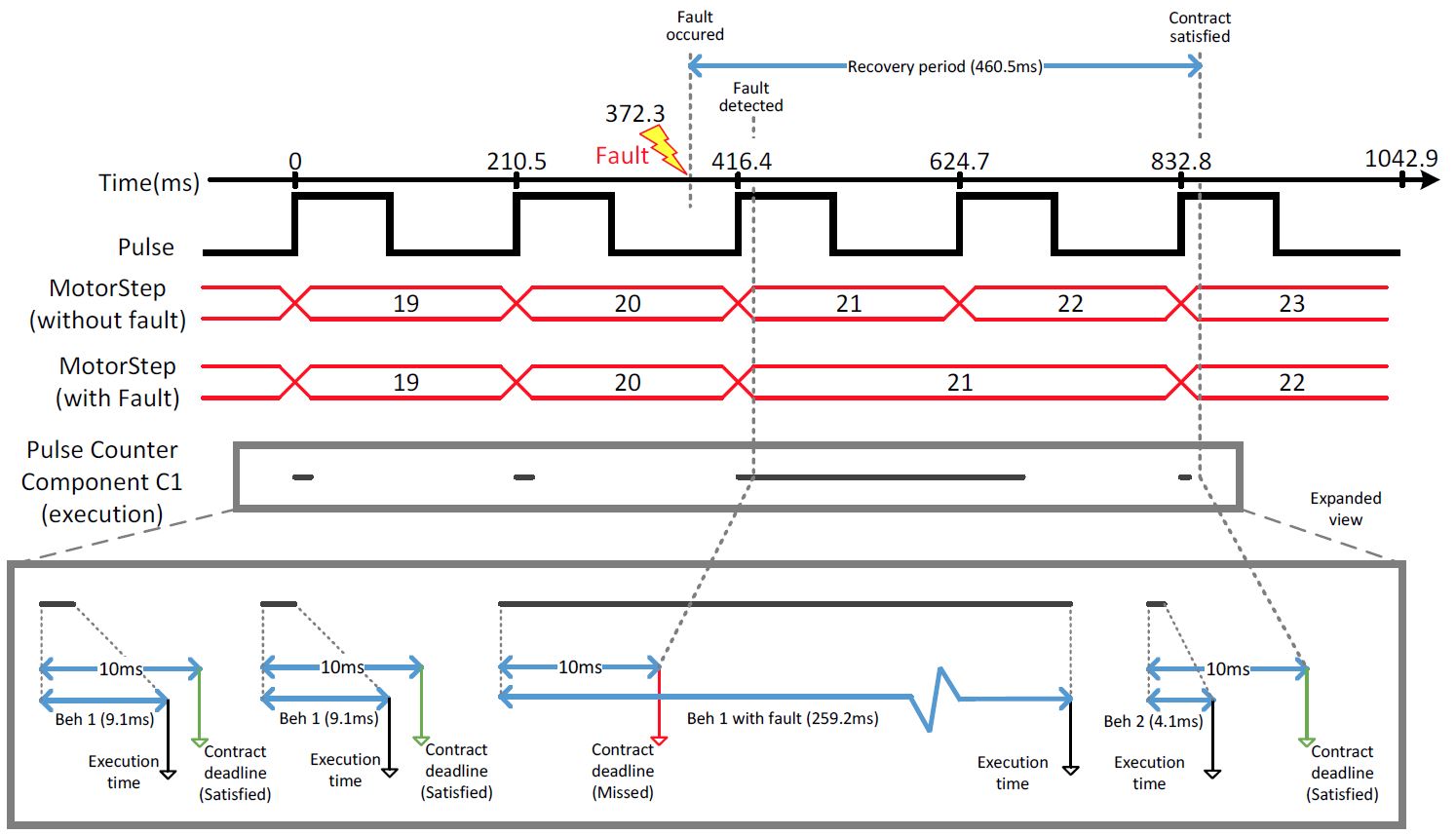
The recovery period for the component is the time from when fault occurred to the point when the contract is once again satisfied. For our example, the recovery period is ms, see Figure 10. Due to the fault, the end-to-end deadline was not satisfied at the application layer. This resulted in an incorrect motorStep value. In the worst case, all work pieces that are on the conveyor belt when the fault occurred may have been sorted incorrectly. Thus, the recovery period is equivalent to the end-to-end delay of the application which is approximately less than seconds. To reduce the application-level recovery time, we can communicate the missed motorStep information to the Controller which can adjust the triggerStep for when the ejectors are to be activated.
VII Conclusions & Future work
To enable a resilient cyber-infrastructure for Industry 4.0, we have presented a new contract-based methodology called CLAIR. Applications are described as a set of modular components that are distributed over a network. Contracts are used for describing the component’s interaction with other components (within and across layers). Finally, the contract are monitored using runtime observers. We detect failures (contract violation) and react (change of contracts) to the disturbances, providing resiliency. Finally, using an industrial case study we have validated the proposed architecture.
In future, we plan to explore efficient communication between resilience managers to reduce system-level recovery period. Also, develop a multi-dimensional resilience metric to evaluate resilience with respect to different performance indicators such as safety, throughput, recovery time, etc.
References
- [1] L. Jay, B. Behrad, and K. Hung-An, “A Cyber-Physical Systems architecture for Industry 4.0-based manufacturing systems,” Manufacturing Letters, vol. 3, pp. 18–23, Jan. 2015.
- [2] W. Dai, V. N. Dubinin, J. H. Christensen, V. Vyatkin, and X. Guan, “Toward Self-Manageable and Adaptive Industrial Cyber-Physical Systems With Knowledge-Driven Autonomic Service Management,” IEEE Transactions on Industrial Informatics, vol. 13, pp. 725–736, Apr. 2017.
- [3] J. Sztipanovits, X. Koutsoukos, G. Karsai, N. Kottenstette, P. Antsaklis, V. Gupta, B. Goodwine, J. Baras, and S. Wang, “Toward a Science of Cyber-Physical System Integration,” Proceedings of the IEEE, vol. 100, pp. 29–44, Jan. 2012.
- [4] E. Scott, I. Madari, A. Dubey, and G. Karsai, “RIAPS: Resilient Information Architecture Platform for Decentralized Smart Systems,” in International Symposium on Real-time Computing, IEEE, May 2017.
- [5] M. G. Valls, I. R. Lopez, and L. F. Villar, “iLAND: An Enhanced Middleware for Real-Time Reconfiguration of Service Oriented Distributed Real-Time Systems,” IEEE Transactions on Industrial Informatics, vol. 9, pp. 228–236, Feb. 2013.
- [6] Function blocks - Part 1: Architecture. Geneva: International Electrotechnical Commission, 2012.
- [7] Function blocks - Part 2: Software tool requirements. Geneva: International Electrotechnical Commission, 2012.
- [8] Function blocks - Part 4: Rules for compliance profiles. Geneva: International Electrotechnical Commission, 2013.
- [9] D. Ratasich, O. Höftberger, H. Isakovic, M. Shafique, and R. Grosu, “A Self-Healing Framework for Building Resilient Cyber-Physical Systems,” in Proceedings of the International Symposium on Real-time Distributed Computing, pp. 133–140, IEEE, May 2017.
- [10] M. Steinegger, A. Zoitl, M. Fein, and G. Schitter, “Design patterns for separating fault handling from control code in discrete manufacturing systems,” in Annual Conference of the IEEE Industrial Electronics Society, pp. 4368–4373, Nov. 2013.
- [11] K. Güttel, “Konzept zur generierung von steuerungscode für fertigungsanlagen unter verwendung wissensbasierter methoden,” in VDI Verlag, vol. 444, 2013.
- [12] F. Luca, A. Massimo, and D. Alessio, “A methodology for fault isolation and identification in automated equipments,” in IEEE International Conference on Industrial Informatics, pp. 157–162, Jul. 2011.
- [13] R. Isermann, “Model-based fault-detection and diagnosis: status and applications,” Annual Reviews in Control, vol. 29, no. 1, pp. 71 – 85, 2005.
- [14] A. Benveniste, B. Caillaud, D. Nickovic, R. Passerone, J.-B. Raclet, P. Reinkemeier, A. Sangiovanni-Vincentelli, W. Damm, T. Henzinger, and K. Larsen, “Contracts for Systems Design: Theory [Research Report] RR-8759,” tech. rep., 2015.
- [15] S. Andalam, D. J. X. Ng, A. Easwaran, and K. Thangamariappan, “Contract-based methodology for developing resilient cyber-infrastructure in the industry 4.0 era,” IEEE Embedded Systems Letters, vol. PP, no. 99, pp. 1–1, 2018.
- [16] A. Davare, D. Densmore, L. Guo, R. Passerone, A. L. Sangiovanni-Vincentelli, A. Simalatsar, and Q. Zhu, “metroII: A Design Environment for Cyber-physical Systems,” ACM Transactions on Embedded Computing Systems, vol. 12, pp. 49:1–49:31, Mar. 2013.
- [17] J. Sztipanovits, T. Bapty, S. Neema, L. Howard, and E. Jackson, OpenMETA: A Model- and Component-Based Design Tool Chain for Cyber-Physical Systems, vol. 8415, pp. 235–248. Berlin, Heidelberg: Springer Berlin Heidelberg, 2014.
- [18] “RTI Connext DDS - Fast, scalable and resilient software connectivity platform.” https://www.rti.com/products/dds (Last visited: 26 July 2017).
- [19] G. Denker, N. Dutt, S. Mehrotra, M.-O. Stehr, C. Talcott, and N. Venkatasubramanian, “Resilient dependable cyber-physical systems: a middleware perspective,” Journal of Internet Services and Applications, vol. 3, pp. 41–49, May 2012.
- [20] I. Friedberg, K. McLaughlin, P. Smith, and M. Wurzenberger, “Towards a Resilience Metric Framework for Cyber-physical Systems,” in International Symposium for ICS & SCADA Cyber Security Research 2016, (UK), pp. 1–4, BCS Learning & Development Ltd., 2016.
- [21] G. Gössler and D. L. Métayer, “A general framework for blaming in component-based systems,” Science of Computer Programming, vol. 113, pp. 223 – 235, 2015.
- [22] S. X. Ding, Model-based Fault Diagnosis Techniques: Design Schemes, Algorithms, and Tools. Springer, 1st ed., Jan. 2008.
- [23] R. S. Z. E. Bhatti and P. S. Roop, “Observer based verification of IEC 61499 function blocks,” in 9th IEEE International Conference on Industrial Informatics, pp. 609–614, Jul. 2011.
- [24] L. Mhamdi, B. Maaref, H. Dhouibi, H. Messaoud, and Z. S. Abazi, “Diagnosis of hybrid systems through observers and timed automata,” in International Conference on Control, Decision and Information Technologies (CoDIT), pp. 164–169, Apr. 2016.
- [25] R. Alur and D. L. Dill, “A Theory of Timed Automata,” Theor. Comput. Sci., vol. 126, pp. 183–235, Apr. 1994.
- [26] T. A. Henzinger, “The theory of hybrid automata,” in Proceedings IEEE Symposium on Logic in Computer Science, pp. 278–292, Jul. 1996.
- [27] “Mathworks - an environment for modelling and simulating combinatorial and sequential decision logic based on state machines and flow charts..” https://www.mathworks.com/products/stateflow.html (Last visited: 18 July 2017).
- [28] G. Pardo-Castellote, “OMG Data-Distribution Service: architectural overview,” in International Conference on Distributed Computing Systems Workshops, pp. 200–206, May 2003.
- [29] L. H. Yoong, P. S. Roop, Z. E. Bhatti, and M. M. Y. Kuo, IEC 61499 in a Nutshell, pp. 17–33. Cham: Springer International Publishing, 2015.
- [30] “4DIAC - Framework for Industrial Automation and Control.” https://eclipse.org/4diac/(Last visited: 13 Sept. 2017).
- [31] A. Zoitl, T. Strasser, and G. Ebenhofer, “Developing modular reusable IEC 61499 control applications with 4DIAC,” in Industrial Informatics, IEEE International Conference on, pp. 358–363, Jul. 2013.
- [32] “ISaGRAF - Workbench from programming IEC61499.” http://www.isagraf.com(Last visited: 13 Sept. 2017).
- [33] “Raspbian - Official operating system supported by RaspberryPi.” https://www.raspberrypi.org/downloads/raspbian/ (Dowloaded on: 05 July 2017).