Reconfigurable Intelligent Surface-Empowered MIMO Systems
Abstract
Reconfigurable intelligent surface (RIS)-assisted communications appear as a promising candidate for future wireless systems due to its attractive advantages in terms of implementation cost and end-to-end system performance. In this paper, two new multiple-input multiple-output (MIMO) system designs using RISs are presented to enhance the performance and boost the spectral efficiency of state-of-the-art MIMO communication systems. Vertical Bell Labs layered space-time (VBLAST) and Alamouti’s schemes have been considered in this study and RIS-based simple transceiver architectures are proposed. For the VBLAST-based new system, an RIS is used to enhance the performance of the nulling and canceling-based sub-optimal detection procedure as well as to noticeably boost the spectral efficiency by conveying extra bits through the adjustment of the phases of the RIS elements. In addition, RIS elements have been utilized in order to redesign Alamouti’s scheme with a single radio frequency (RF) signal generator at the transmitter side and to enhance its bit error rate (BER) performance. Monte Carlo simulations are provided to show the effectiveness of our system designs and it has been shown that they outperform the reference schemes in terms of BER performance and spectral efficiency.
Index Terms:
Reconfigurable intelligent surface (RIS), MIMO systems, error probability analysis, VBLAST, Alamouti’s scheme.I Introduction
Reconfigurable intelligent surfaces (RISs) have received significant attention from the wireless communication community as effective, cheap, reconfigurable, easy to deploy, and passive system modules that can be used to control the wireless propagation environment by re-engineering the electromagnetic waves [1], [2]. Manipulating the propagation environment using RISs has been regarded as a promising candidate for the next-generation wireless technologies such as Terahertz communications, non-orthogonal multiple access (NOMA), and low-cost massive multiple-input multiple-output (MIMO) systems. Without loss of generality, mitigating the fading channel impairments and compensating for the propagation losses in order to enhance the signal quality at the receiver side are the main objectives behind the development of this technology. Nevertheless, RISs can also be utilized to minimize the transmitted signal power, to boost the system transmission capacity, and to enhance the physical layer security [3], [4].
In the preliminary study of [5], RISs are employed for two different purposes. First, an RIS is used to realize an ultra-reliable communication scheme that operates at considerably low signal-to-noise ratio (SNR) values. While in the second scenario, an RIS is used as an access point to create virtual phase shift keying (PSK) symbols at the receiver side. The latter concept is also used to perform index modulation at the receiver side [6]. Considering a dual-hop communication scenario, the authors in [7] proposed an RIS-based space shift keying system where the RIS is used as a reflector which is positioned between a transmitter with multiple antennas and a receiver with a single antenna. In [8], the indoor multiple-user network-sharing capacity is enhanced by optimally adjusting the phases of a passive reconfigurable reflect-array to cancel the interference and enhance the users’ signal quality. An energy efficient multiple-input single output (MISO) system is proposed in [9], by jointly optimizing the transmit powers of the users and the phases of RIS elements. In [10], the authors proposed an RIS-assisted simultaneous wireless information and power transfer system, where an information decoding set and energy harvesting set of single-antenna receivers are served by a multiple-antenna access point. In [11], the authors investigated the use of artificial noise in order to increase the secrecy rate in an RIS-based communication system, where a single-antenna user is served by a multiple-antenna transmitter in the presence of multi-antenna eavesdroppers. In [12] and [13], the received signal power for a MISO user is maximized by optimizing the active beamforming at the transmitter jointly with the passive beamforming at the RIS by adjusting its phase shifters. The latter concept is also used in [14], where the beamformer at the access point and RIS are jointly optimized in order to increase the spectral efficiency for an RIS-assisted multi-user MISO system. In [15], an RIS-assisted multi-user MISO system is considered with different channel types where RIS phase optimization is utilized in order to maximize the minimum signal-to-noise-and-interference ratio (SNIR). RIS is used in [16] to improve the channel rank for MIMO systems by adding additional multipaths with distinctively different spatial angles in addition to the low-rank direct channel path. RIS reflection coefficients and the transmit covariance matrix are jointly optimized in [17] in order to maximize the capacity of a point-to-point MIMO system. In [18], the authors consider the channel estimation problem in multi-user MIMO systems and propose an uplink channel estimation protocol to estimate the cascaded channel from the base station to the RIS and from the RIS to the user. The use of passive intelligent mirrors (PIM) with a multi-user MISO downlink system is investigated in [19], where the transmit powers and the PIM reflection coefficients are designed to maximize the sum-rate considering the individual quality of service for mobile users. An overview of the holographic MIMO surface is presented in [20], where the authors investigated their hardware architectures, functionalities, and characteristics. In [21], the authors exploited the deep learning reinforcement to jointly obtain the optimum beamforming matrix and the RIS phase shifts where the introduced algorithm learns directly from the environment and updates the beamforming matrix and RIS phase shifts accordingly. Based on cosine similarity theorem, a low-complexity RIS phase shift design algorithm is proposed in [22], where the RIS is used to assist a MIMO communication system. In [23] and [24], the authors investigated physical channel modeling for mmWave bands considering indoor and outdoor environments. Furthermore, the authors provided an open-source comprehensive channel simulator which can be used to examine the different channel models discussed in their work. However, the use of RISs to boost the spectral efficiency and/or reliability of existing MIMO systems along with applications of index modulation (IM) is not well explored in the open literature. Against this background, two new RIS-assisted communication schemes are presented in this paper by focusing on the integration of RISs into the existing MIMO systems in a simple and effective way. VBLAST [25] and Alamouti’s schemes [26] are considered in this study as the most common and practical MIMO schemes while a generalization to other advanced MIMO signaling schemes might be possible using our concept. We summarize the main contributions of this paper as follows:
-
•
We propose an RIS-assisted Alamouti’s scheme in which we redesign the classical Alamouti’s scheme with a single RF signal generator at the transmitter side instead of two RF chains.
-
•
We show that our RIS-assisted Alamouti’s scheme preserves the diversity order of the classical Alamouti’s scheme and provides a significant BER performance enhancement.
-
•
We propose an RIS-assisted and IM-based VBLAST scheme using nulling and cancelling-based sub-optimal detection with zero forcing (ZF) technique. Compared to the classical VBLAST scheme, we show that our proposed RIS-assisted and IM-based VBLAST scheme provides superior performance in terms of the spectral efficiency and the BER performance.
-
•
For RIS-assisted and IM-based VBLAST scheme, we propose two novel nulling-based optimal and sub-optimal detectors to detect the indices of the antennas targeted by the IM.
In RIS-assisted Alamouti’s scheme, at the receiver side, the classical Alamouti’s detector is used to recover the transmitted symbols, assuming that the channel state information (CSI) is available at this unit. It is worth noting that, for our RIS-assisted scheme, no CSI is needed at the RIS side, which reduces the overhead for CSI acquisition and simplifies the RIS design. Compared to the blind RIS-AP scheme in [5] and the classical Alamouti’s scheme, our results show that the proposed scheme provides a significant improvement in the BER performance. Furthermore, theoretical analysis and simulations results of the RIS-assisted Alamouti’s scheme show that the same concept can be generalized to space-time block code (STBC) systems. In other words, in a large scale MIMO setup, our scheme can replace a large number of RF chains at the transmitter side by a single RF signal generator. Furthermore, our RIS-assisted scheme can provide a significant BER performance enhancement while preserving the diversity order of the STBC system. In RIS-assisted and IM-based VBLAST scheme, the RIS can be operated in multiple modes with and without IM. With IM, the RIS eliminates the channel phases between a specific transmit-receive antenna pair, which is selected according to the additional information bits in an IM fashion. On the other hand, without IM, the RIS eliminates the channel phases between a fixed and predefined antenna pair in order to provide the maximum BER performance enhancement. In this scheme, the CSI between each transmit-receive antenna pair through the RIS is required at both the RIS and the receiver side. At the receiver side, the IM bits are obtained using our novel nulling-based detectors while the transmitted symbols will be detected as in the plain VBLAST scheme using ZF-based nulling and cancelling algorithm without requiring additional signal processing steps [25]. The proposed schemes are simple in design and do not require major modifications for the state-of-the-art systems. Furthermore, comprehensive computer simulations are provided in this study under realistic environment setups to assess their practical feasibility.
The rest of the paper is organized as follows. In Section II, we introduce the system model of the RIS-assisted Alamouti’s scheme and evaluate its symbol error probability (SEP). Section III introduces the RIS-assisted and IM-based VBLAST scheme, the nulling-based detectors, and the analysis of the computational complexity of the receiver. In Section IV, we provide our computer simulation results and comparisons along with path loss models considered in these simulations. Finally, conclusions are given in Section V.
II RIS-Assisted Alamouti’s scheme: signal model and error performance analysis
In the proposed RIS-assisted Alamouti’s scheme, an unmodulated carrier signal is being transmitted from a low-cost RF signal generator close to the source (S) unit. The RF signal generator contains an RF digital-to-analog converter with an internal memory and a power amplifier as discussed in [5].
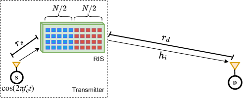
Fig. 1 shows the block diagram of the proposed scheme where and are the distances (in meters) of S-RIS and RIS-D, respectively. is selected in a way that the channel between S and RIS is assumed to be line-of-sight (LOS) dominated. In our setup, the RIS is divided into two parts each having elements adjusted to a common reflection phase value. Each part employs two different common reflection phase values over two time slots. The proposed system emulates the Alamouti’s scheme by adjusting the phases of the RIS elements to modify the RF carrier signal and invoke the phases of the two data symbols. In this way, the Alamouti’s scheme can be redesigned with a single RF signal generator instead of two full RF chains at the transmitter side. The RIS is a blind one with respect to the CSI, while its intelligent stems from the fact that it adjusts the unmodulated RF signal to mimic the PSK symbol phases. In this study, due to the high path loss experienced by the signals reflected from the RIS, the power of the signals reflected from the RIS for two or more times is ignored and only the first reflection is considered in our signal model [12].
Let denotes the small-scale fading channel coefficient
between the destination (D) and element of the RIS, we have under Rayleigh fading assumption, where stands for complex Gaussian distribution with zero mean and variance. and stand for the phases of two M-PSK symbols to be transmitted according to bits. Assuming quasi-static fading channels, where the channels will remain constant over the two time slots, the received signal at the first time slot can be written as
| (1) |
where is the additive white Gaussian noise (AWGN) sample at the first time slot, . is the transmitted RF signal energy and and are the common RIS reflection phases for the first and second parts, respectively, for the first time slot. is the total path gain (loss), and more details regarding the considered path loss model and environmental setups will be given in Section IV. According to the Alamouti’s transmission scheme, in the second time slot, we obtain the following received signal by carefully adjusting the common RIS phase terms as and for the first and second parts, respectively:
| (2) |
where . Defining , , and , (1) and (2) can be re-expressed as
| (3) | ||||
| (4) |
where and stand for two virtual -PSK symbols to be delivered to the receiver and is the modulation order. As in the classical Alamouti’s scheme, the combiner will construct the combined signals as follows:
| (5) |
| (6) |
Then, and will be passed to the maximum likelihood (ML) detector to estimate and . Considering the symmetry of and , the instantaneous received SNR per symbol can be obtained as
| (7) |
Considering , we obtain and . Consequently, becomes a central chi-square distributed random variable with four degrees of freedom with the following MGF [27]:
| (8) |
From (8), the average symbol error probability (SEP) for M-PSK signaling can be obtained as [28]
| (9) |
which can be simplified for BPSK as
| (10) |
From (9), we observe that a transmit diversity of order two is still achieved by this scheme due to the fact that the RIS mimics a similar transmission methodology to the Alamouti’s scheme over two time slots and preserves its orthogonality. Furthermore, the transmitted symbols have an SNR amplification achieved by the combination of the signals reflected from the RIS, where the SNR is enhanced by a factor of N, as seen from (10).
III RIS-Assisted and IM-Based VBLAST SYSTEM: The signal model
The proposed RIS-assisted and IM-based VBLAST scheme is assumed to utilize the RIS through a feedback link to eliminate the channel phases between a transmit-receive antenna pair. Instead of randomly selecting it, this transmit-receive antenna pair is selected according to the bits incoming to the RIS from S through the feedback link, in IM fashion. This means that the proposed scheme benefits from the RIS in an effective way. Consequently, with the help of the RIS, the proposed scheme provides a significant BER performance enhancement and an effective boost in the spectral efficiency compared to the classical VBLAST scheme. The proposed scheme is shown in Fig. 2, where an VBLAST system is being
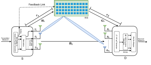
operated along with an RIS with reflecting elements. The RIS-assisted and IM-based VBLAST scheme can be operated in three different modes namely, i) full IM mode, ii) partial-IM mode, and iii) enhancing mode. In what follows, we describe these three operating modes.
In the full-IM mode, at the transmitter side, the IM-based mapping and transmission can be described as follows. The incoming bits will be divided into two groups, the first group of bits will be used to select independent -QAM symbols to be transmitted from the available transmitting antennas at S, as in classical VBLAST scheme.
The second group of bits, where is assumed to be an integer power of two and corresponds to the all possible transmit-receive antenna combinations, is sent through a feedback link from S to the RIS. The RIS uses these incoming bits to select the indices of the transmit and receive antennas, shown by and , corresponding to a pair of antennas, respectively. According to the CSI associated with the selected antenna pair, the phase shifts of the RIS elements will be adjusted to make the -RIS- equivalent channel phases equal to zero. Consequently, the signals transmitted from and reflected from the RIS will constructively combine to provide SNR amplification at . The overall spectral efficiency of the system becomes bits per channel use (bpcu).
In the partial-IM mode, the transmission procedure is the same as in the full-IM mode except that a smaller set of the transmit-receive antenna combinations is used to convey the IM bits. That is, the index of the targeted transmit antenna is determined first and the same index is used for the targeted receive antenna, . Hence, there are only possible combinations that can be used to convey the IM bits. The resulting spectral efficiency under this mode will be bpcu, where the motivation here is to sacrifice spectral efficiency gained by IM in order to further enhance the BER performance through increasing the reliability of IM bits.
Finally, in the enhancing mode, IM is not performed at all and therefore, there is no need for a feedback link between S and D, instead, a fixed and predefined antenna pair will always be targeted by the RIS for the elimination of channel phases. Consequently, the best BER performance is achieved while preserving the same spectral efficiency for classical VBLAST, . For all operating modes, we assume that perfect CSI is available at the both RIS and receiver side. The acquisition of CSI in RIS-based systems is discussed in [18], [29], [30]. We describe our scheme with an example.
Example: A RIS-assisted VBLAST system operated in the full-IM mode with QPSK modulation transmits the bitstream of as follows. The first bits are modulated to QPSK symbols and transmitted, in parallel, from the available transmit antennas. The remaining bits are used by the RIS to select the pair , since we implement the following mapping rule: and . The RIS adjusts the reflection phases to eliminate the channel phases between and . Here, we assume that the adjustment of the phases of the RIS elements and the -QAM symbols’ transmission from S are being performed simultaneously. On the other hand, the receiver tries to first estimate the indices of the selected antennas, and then successively detects the independent -QAM symbols.
For an VBLAST system assisted by an RIS with reflectors, the vector of the received signals can be written as [31]
| (11) |
where , are the S-RIS and RIS-D, uncorrelated Rician fading channel matrices, respectively. The S-D channel matrix is a random matrix where its elements are independent and identically distributed (i.i.d) complex Gaussian random variables (RVs) with zero mean and unit variance, . is the Rician factor standing for the ratio of LOS and NLOS power and is the matrix of RIS reflection phases. In theory, each RIS element can be adjusted to any arbitrary phase shift, , however, this is challenging to implement in practice. Therefore, in implementation, the RIS elements are being designed so that they can be adjusted to a finite number of discrete phase shifts. Hence, assuming uniform quantization for the interval , the phase shift associated with each RIS element can be controlled by bits that correspond to possible different phase shifts belong to the finite set , where [32]. is the vector of transmitted -QAM symbols, is the S-RIS-D and S-D equivalent channel matrix and is the vector of AWGN noise samples. and are the total path losses for S-RIS-D and S-D transmission paths, respectively, and more details are given in Section IV. The received signal by the receiving antenna () can be represented as
| (12) |
where and is the S-D channel vector for the receiving antenna. is the RIS-D channel vector for the receiving antenna, and is the AWGN sample with . Expanding (12), we have
| (13) |
| where is the S ( transmitting antenna)-RIS |
| (element) channel coefficient and is RIS |
| (element)-D ( receiving antenna) channel coefficient. In |
this way, in order to eliminate the phases of the S-RIS-D channel between the antenna pair , elements’ phases of the RIS are adjusted as , and (13) can be re-expressed for the receive antenna as
| (14) |
(14) can be interpreted as follows. The first term illustrates the amplification gained by the constructive combining of the signals reflected from the RIS and belongs to the symbol . This constructive combining will result in an SNR gain of for this symbol as in [5]. Hence, the BER performance of this symbol will be boosted up and consequently, it will be the strongest symbol where the nulling and canceling algorithm starts with. This also means that the error propagation from the first symbol to the remaining ones will be significantly mitigated and the overall BER performance will be improved. The second term shows the destructive interference of the signals reflected from the RIS, which belongs to the other symbols. Finally, the third term corresponds to the interference received by the receiving antenna through the S-D transmission path for all the transmitted symbols. Hence, compared to the classical VBLAST, an RIS will introduce times extra interference for each received symbol. Nevertheless, assuming that the CSI over S-RIS-D is available at the receiver side, then this interference can be handled readily.
III-A Detection Algorithms
At the receiver side, we introduce two novel nulling-based detectors to detect the transmit-receive antenna indices targeted by the RIS for channel phases elimination. According to Algorithm 1, the optimal detector performs an exhaustive search for and jointly, as follows. For each iteration, the detector determines and then constructs . Next, the nulling-based procedure will be used to detect the first symbol, which has the highest SNR, assumed to be transmitted and received by the antenna pair . Finally, the pair and associated with the symbol that has the minimum squared Euclidean distance will be picked as the pair and .
In Algorithm 1, is the index-estimated S-RIS-D and S-D equivalent channel matrix assuming the antenna pair was targeted by the RIS for channel phases elimination. is the diagonal RIS phases matrix where its element corresponds to the phase elimination for the S-RIS-D channel between and . is Moore-Penrose pseudo-inverse operator, , where is the Hermitian operator. is the row of . is the index of the row, which has the minimum squared Euclidean norm, of the matrix , corresponding to the symbol with the highest SNR. is the row of , is the symbol after nulling the interference of the other symbols. returns the squared Euclidean distance, , of the closest -QAM symbol associated with . Hence, associated with the minimum distance is the most likely the equivalent channel matrix that corresponds to the current adjustment of the RIS phases.
By estimating and , the IM bits conveyed by the adjustment of the RIS phases will be obtained. In order to reduce the complexity of the detector proposed in Algorithm 1, the receiving antenna index, , can be detected using a greedy detector instead of the joint exhaustive search for and . In this way, can be detected by finding the receiving antenna with the highest instantaneous energy:
| (15) |
Next, a nulling-based procedure is used to search for while fixing found from (15). This detector is represented as a sub-optimal one and Algorithm 2 illustrates its detection steps.
After obtaining the S-RIS-D and S-D equivalent channel matrix, , it will be used by Algorithm 3 to detect the independent symbols as in the case of classical VBLAST [25]. In Algorithm 3, is the slicing function, is the column of and is pseudo inverse of the matrix obtained by zeroing the columns of with indices , , …. Finally, is the signal vector after subtracting the interference contribution of the previously detected symbol .
III-B Computational Complexity Analysis
At the receiver side, first, the RIS-assisted VBLAST scheme uses Algorithm 1 or Algorithm 2 to detect the indices and . Second, the receiver uses Algorithm 3 to detect the transmitted -QAM symbols. Here, we calculate the computational complexity associated with Algorithms 1, 2, and 3.
Denoting the total number of complex multiplications (CMs) required by Algorithms 1, 2, and 3 as , , and , respectively, then from Table 1, , and can be calculated as follows
| (16) | ||||
| (17) |
| (18) |
In order to provide a useful insight on the overall complexity, let . Then (16), (17), and (18) can be rewritten as
| (19) | ||||
| (20) | ||||
| (21) |
From (16) and (17), it can be seen that the number of antennas and the number of RIS reflecting elements both have a significant contribution to the computational complexity of detecting the antenna indices and . This is still valid even if we consider the fact that is, practically, much larger than , since the latter still has a higher exponent. From (19) and (20), the overall computational complexity level can be obtained as , and , for Algorithms 1 and 2, respectively. Comparing both algorithms, we observe that the overall computational complexity is dominated by that of constructing . Compared to the classical VBLAST scheme, where the receiver computational complexity will be equivalent to that of Algorithm 3 only, , RIS-assisted IM-based VBLAST scheme has an extra complexity of and for Algorithms 1 and 2, respectively.
| Operation | CMs |
|---|---|
| Searching for | |
| Constructing | + |
| Pseudo inverse of | |
| Ordering | |
| Nulling | |
| Getting |
The cost of this additional complexity stems for the construction of , which is required to detect the transmitted symbols and the indices of the targeted transmit-receiving antennas. In a brief, or is the additional computational complexity that is required to operate a classical VBLAST system as an RIS-assisted system.
IV Simulation results
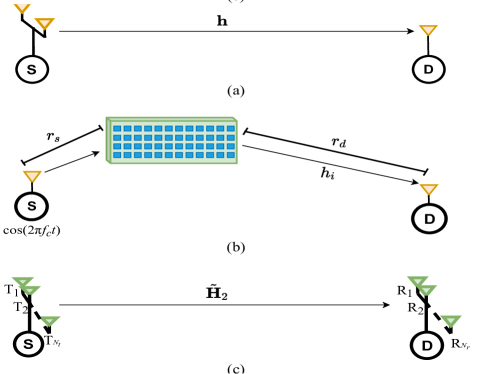
In this section, exhaustive computer simulations are provided for the proposed schemes against their counterparts. We consider realistic setups and path loss models where both transmitter and receiver located in an indoor environment and Fig. 3 shows the block diagrams of the benchmark schemes. In all simulations, the SNR is defined to be . Furthermore, perfect CSI is assumed to be available for the proposed and benchmark schemes at the receiver side only, except RIS-assisted and IM-based VBLAST scheme where the CSI need also to be available at the RIS side.
Figs. 3 (a) and (c) show the system setups for the classical Alamouti and VBLAST schemes, where the S-D channel is assumed to follow a Rayleigh fading (i.e., consist of a non-LOS link). For the RIS-AP scheme shown in Fig. 3 (b), the S-D transmission path is assumed to be fully blocked by obstacles and the only transmission path is through the RIS, where the S-RIS path is LOS dominated and the RIS-D path follow Rayleigh fading [5].
For classical VBLAST and Alamouti schemes, where there is no RIS, the path loss is calculated for an operating frequency of GHz, as follows [33]
| (22) |
where is the S-D separation distance, dB is the path loss at one meter distance, and dB corresponds to the path loss of two walls each having dB of path loss.
For the RIS-assisted Alamouti and RIS-AP schemes, the S-RIS-D path loss, , is calculated as follows [34]
| (23) |
where is the wavelength of the operating frequency ( GHz). Finally, for RIS-assisted and IM-based VBLAST scheme, and are calculated from (22) and (23), respectively. For RIS-assisted Alamouti, RIS-AP, and classical
Alamouti’s schemes we have , , , and . On the other hand, for RIS-assisted and IM-based VBLAST and classical VBLAST schemes, we have , , , and .
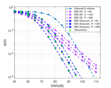
Fig. 4 illustrates the BER performance of the RIS-assisted Alamouti’s scheme versus the classical Alamouti’s scheme for a MISO system and the blind case of RIS-AP in [5]. We observe that a second order transmit diversity is achieved using a single RF signal generator thanks to the RIS. Furthermore, the influence of the number of RIS elements on the BER performance is shown to be significant, where a 10 dB gain is achieved with RIS elements. As it can be verified from (1), the increase of the number of RIS elements enhances the BER performance linearly, where a dB gain is achieved by doubling . Hence, the RIS-assisted Alamouti’s scheme outperforms the classical Alamouti’s scheme in terms of the BER performance and the required RF resources on the transmitter side. Also, compared to the blind scheme of RIS-AP in [5], we see that the proposed scheme clearly shines out by a diversity of order two due to the orthogonality of Alamouti’s transmission matrix.
For the RIS-assisted and IM-based VBLAST scheme, we considered the existence and absence of a LOS component for the S-RIS, and RIS-D channels. Therefore, the simulations are performed with and dB, where values can change dramatically within the same indoor environment depending on the location of the transmitter and receiver [35].
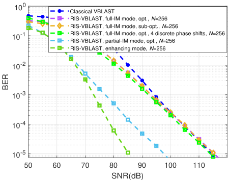
In Figs. 5 and 6, we compare RIS-assisted and IM-based VBLAST with classical VBLAST for MIMO setup. Algorithms 1 and 2 correspond to the optimal and sub-optimal detectors for the transmit-receive antenna indices and they are denoted in Figs. 5 and 6 by “opt.” and “sub-opt.”, respectively. Here, the spectral efficiency of classical VBLAST is b/s/Hz, while it is and b/s/Hz for the RIS-assisted and IM-based VBLAST, in partial and full-IM modes, respectively, with BPSK. Thus, the spectral efficiency for the RIS-assisted IM-based VBLAST is significantly boosted compared to the classical VBLAST due to the extra IM bits conveyed by our antenna pair selection methodology.
In Fig. 5 we compare the BER performance of RIS-assisted and IM-based VBLAST scheme, under the Rayleigh fading assumption for the S-RIS-D transmission path, with classical VBLAST scheme. We observe that the proposed scheme operated in full-IM mode provides an improved BER at low to mid SNR values, while saturating to the BER performance of the classical VBLAST at high SNR. Nevertheless, compared to the classical VBLAST scheme, the spectral efficiency is doubled for the proposed scheme. In addition, the sub-optimal detector represented by Algorithm 2 is shown to achieve the same performance as for the optimal one, which is represented by Algorithm 1. This means that the detection process of the antenna indices can be simpler in terms of the complexity level. It can be also seen that the performance of the continuous phases adjustment can be almost achieved with only four discrete phase shifts [32], [36]. In this way, the RIS design can be simplified to control the phase shift of each element using 2-bits only.
Furthermore, the partial-IM and enhancing modes show a significant BER performance gain of and dB, respectively, compared to the classical VBLAST scheme. It is worth noting that, the partial-IM scheme increases the spectral efficiency by .
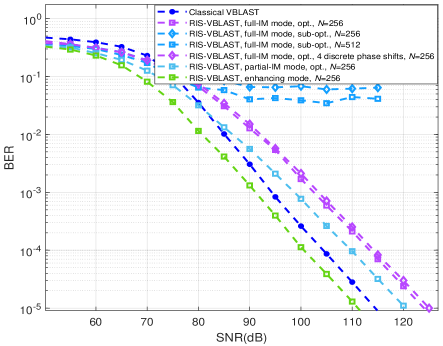
In Fig. 6, the BER performance curves are shown for the RIS-assisted and IM-based VBLAST scheme considering the existence of LOS component ( dB) between S and the RIS, and between the RIS and D. Compared to the classical VBLAST scheme, the impact of the LOS component on the RIS performance can be clearly seen for the proposed scheme. The full-IM and partial-IM modes need an SNR increase of - dB in order to increase the spectral efficiency by and fold, respectively. This can be explained by the lack of diversity due to the LOS component in the S-RIS and RIS-D channels. Therefore, the receiver makes more errors while detecting the targeted antenna indices, and . Since the construction of depends on and , the erroneous detection of them reflects on the detection of the -QAM symbols. Furthermore, it can be noted that the sub-optimal (greedy) detector provides an error floor even with an RIS of elements. This is, also, due to the LOS component, which makes the difference in the instantaneous energy, received by all the receiving antennas, trivial. Nevertheless, the enhancing mode still provides a BER performance gain of dB compared to the classical VBLAST scheme.
Comparing the three operating modes, Fig. 5 and 6 show that the enhancing mode, where there is no IM, achieves the best BER performance. This is due to the fact that, in enhancing mode, the amplification is directed towards a fixed and predefined antenna pair. Furthermore, the proposed scheme has the flexibility to operate in one of these three modes according to the value, hence, increase the spectral efficiency and/or enhance the BER performance accordingly.
Finally, it is worth noting that, from (22) and (23), comparing the S-RIS-D and S-D communication links, we obtain dB additional path loss, under the given separation distances, for RIS-AP and RIS-assisted Alamouti schemes compared to the classical Alamouti’s scheme. In the same way, for RIS-assisted and IM-based VBLAST scheme, where there are two communication links, there is an additional path loss of dB for the S-RIS-D compared to the S-D communication link. This shows that the transmission over the RIS has considerably higher path loss compared to the direct transmission without RIS. Nevertheless, the additional path loss can be compensated by choosing the proper RIS size [34], [37], as we showed in our proposed schemes.
V Conclusion
In this paper, we have proposed novel designs for MIMO systems with the assistance of RISs. Although only VBLAST and Alamouti’s schemes have been considered in this study, our concepts can be applied for other MIMO schemes as well. Applying the considered concept to space-time codes in large scale MIMO setups with a large number of antennas may show the remarkable advantage for this scheme by utilizing a single RF signal generator instead of multiple RF chains. Furthermore, RIS-assisted Alamouti’s scheme is capable of achieving an times SNR enhancement in addition to a transmit diversity order of two and the RIS-assisted IM-based VBLAST scheme is able to provide a significant BER performance gain in addition to the noticeable increasing in the spectral efficiency by the smart methodology of channel phases elimination. Considering the simplicity of implementation and deployment, both schemes do not require a significant reconfiguration for the existing MIMO setups, particularly in their receiver architectures, which makes them practical and feasible alternatives for future wireless systems. The design of a practical phase shift model, that captures the phase-dependent amplitude variation, for the proposed schemes appears as interesting problem which we will consider in our future research.
References
- [1] E. Basar, M. Di Renzo, J. de Rosny, M. Debbah, M.-S. Alouini, and R. Zhang, “Wireless communications through reconfigurable intelligent surfaces,” IEEE Access, vol. 7, pp. 116753 - 116773, Aug. 2019.
- [2] Q. Wu, R. Zhang, “Towards smart and reconfigurable environment: intelligent reflecting surface aided wireless network,” IEEE Commun. Mag., vol. 58, no. 1, pp. 106 - 112, Jan. 2020.
- [3] S. Gong et al., “Towards smart wireless communications via intelligent reflecting surfaces: A contemporary survey,” IEEE Communications Surveys & Tutorials (to appear).
- [4] J. Zhao, “A survey of intelligent reflecting surfaces (irss): Towards 6g wireless communication networks,” Nov. 2019. [Online]. Available: arXiv:1907.04789.
- [5] E. Basar, “Transmission through large intelligent surfaces: A new frontier in wireless communications,” in Proc. European Conf. Netw. Commun. (EuCNC 2019), Valencia, Spain, June 2019.
- [6] ——, “Reconfigurable intelligent surface-based index modulation: A new beyond MIMO paradigm for 6G,” IEEE Trans. Comm., vol. 68, no. 5, May 2020.
- [7] A. E. Canbilen, E. Basar, S. S. Ikki, “Reconfigurable intelligent surface-assisted space shift keying,” IEEE Wireless Commun. Lett. (to appear).
- [8] X. Tan, Z. Sun, J. M. Jornet, and D. Pados, “Increasing indoor spectrum sharing capacity using smart reflect-array,” in Proc. 2016 IEEE Int. Conf. Commun. (ICC), Kuala Lumpur, Malaysia, May 2016, pp. 1–6.
- [9] C. Huang, G. C. Alexandropoulos, A. Zappone, M. Debbah, and C. Yuen, “Energy efficient multi-user MISO communication using low resolution large intelligent surfaces,” in Proc. IEEE Global Commun. Conf., Abu Dhabi, UAE, Dec. 2018.
- [10] Q. Wu, R. Zhang, “Weighted sum power maximization for intelligent reflecting surface aided SWIPT,” IEEE Wireless Commun. Lett., vol. 9, no. 5, pp. 586-590, May 2020.
- [11] X. Guan, Q. Wu, R. Zhang, “Intelligent reflecting surface assisted secrecy communication: Is artificial noise helpful or not?” IEEE Wireless Commun. Lett., vol. 9, no. 6, pp. 778-782, June 2020.
- [12] Q. Wu, R. Zhang, “Intelligent reflecting surface enhanced wireless network: Joint active and passive beamforming design,” in Proc. IEEE Global Commun. Conf., Abu Dhabi, UAE, Dec. 2018. [Online]. Available:arXiv:1809.01423.
- [13] ——, “Intelligent reflecting surface enhanced wireless network via joint active and passive beamforming,” IEEE Trans. Wireless Commun., vol. 18, no. 11, pp. 5394-5409. Nov. 2019.
- [14] X. Yu, D. Xu, and R. Schober, “MISO wireless communication systems via intelligent reflecting surfaces,” in Proc. 2019 IEEE/CIC Int. Conf. Commun. (ICCC), Changchun, China, Aug. 2019. [Online]. Available: arXiv:1904.12199.
- [15] Q.-U.-A. Nadeem, A. Kammoun, A. Chaaban, M. Debbah, and M.-S. Alouini, “Asymptotic max-min SINR analysis of reconfigurable intelligent surface assisted MISO systems,” IEEE Trans. Wireless Commun. (to appear).
- [16] Ö. Özdogan, E. Björnson, E. G. Larsson, “Using intelligent reflecting surfaces for rank improvement in MIMO communications,” in Proc. IEEE Int. Conf. on Acoustics, Speech and Signal Processing (ICASSP). Barcelona, Spain. May 2020.
- [17] S. Zhang, R. Zhang, “Capacity characterization for intelligent reflecting surface aided mimo communication,” IEEE J. Sel. Areas Commun. (to appear).
- [18] J. Chen, Y.-C Liang, H. V. Cheng, W. Yu, “Channel estimation for reconfigurable intelligent surface aided multi-user mimo systems,” Dec. 2019 [Online]. Available: arXiv: 1912.03619.
- [19] C. Huang, A. Zappone, M. Debbah, C. Yuen, “Achievable Rate Maximization by Passive Intelligent Mirrors,” in Proc. IEEE Int. Conf. on Acoustics, Speech and Signal Processing (ICASSP). Calgary, AB, Canada, Apr. 2018.
- [20] C. Huang, S. Hu, G. C. Alexandropoulos, A. Zappone, C. Yuen, R. Zhang, M. Di Renzo, M. Debbah, “Holographic MIMO surfaces for 6G wireless networks: Opportunities, challenges, and trends,” IEEE Wireless Commun. (to appear).
- [21] C. Huang, R. Mo, C. Yuen, “Reconfigurable intelligent surface assisted multiuser MISO systems exploiting deep reinforcement learning,” IEEE J. Sel. Areas Commun. (to appear).
- [22] Z. Yigit, E. Basar, I. Altunbas, “Low complexity adaptation for reconfigurable intelligent surface-based MIMO systems,” Jun. 2020. [Online]. Available: arXiv:2006.03247.
- [23] E. Basar, I. Yildirim, I. F. Akyildiz, “Indoor and outdoor physical channel modeling and efficient positioning for reconfigurable intelligent surfaces in mmWave bands,” May. 2020. [Online]. Available: arXiv:2006.02240.
- [24] ——, “SimRIS channel simulator for reconfigurable intelligent surface-empowered communication systems,” May. 2020. [Online]. Available: arXiv:2006.00468.
- [25] P.W. Wolniansky, G.J. Fosni, G.D. Golden, R.A. Valenzuela, “V-BLAST: An architecture for realizing very high data rates over the rich-scattering wireless channel,” 1998 URSI International Symposium on Signal, System and Electronics, Pisa, Italy, pp. 295-300, Sep. Oct 1998.
- [26] S. Alamouti, “A simple transmit diversity technique for wireless communications,” IEEE J. Sel. Areas Commun., vol. 16, no. 8, pp. 1451-1458, Oct. 1998.
- [27] J. G. Proakis, Digital Communication. 5th ed. New York: McGrawHill, 2008.
- [28] M. Simon, M. S. Alaouni, Digital Communications over Fading Channels. 2nd ed. New Jersey: John Wiley and Sons, 2005.
- [29] L. Wei, C. Huang, G. C. Alexandropoulos, C. Yuen, “Parallel factor decomposition channel estimation in RIS-assisted multi-user MISO communication,” IEEE 11th Sensor Array and Multichannel Signal Processing Workshop (SAM). Hangzhou, China. Jun. 2020.
- [30] J. He, M. Leinonen, H. Wymeersch, M. Juntti, “Channel estimation for RIS-aided mmWave MIMO channels,” Feb. 2020. [Online]. Available: arXiv:2002.06453.
- [31] C. Huang, A. Zappone, G. C. Alexandropoulos, M. Debbah, C. Yuen, “Reconfigurable intelligent surfaces for energy efficiency in wireless communication,” IEEE Trans. Wireless Commun., vol. 18, no. 8. Aug. 2019.
- [32] Q. Wu, R. Zhang, “Beamforming optimization for wireless network aided by intelligent reflecting surface with discrete phase shifts,” IEEE Trans. on Commun., vol. 68, no. 3, March 2020.
- [33] E. Damosso, L. M. Coreia, COST Action 231: Digital Mobile Radio Towards Future Generation Systems: Final Report, 1999.
- [34] S.W. Ellingson, “Path loss in reconfigurable intelligent surface-enabled channels,” Dec. 2019. [Online]. Available: arXiv:1912.06759.
- [35] C.H.Y. Eugene, K. Sakaguchi , K. Araki, “Experimental and analytical investigation of MIMO channel capacity in an indoor line-of-sight (LOS) environment,” in Proc. IEEE Int. Symp. Pers. Indoor Mobile Radio Commun. (IEEE Cat. No.04TH8754), Barcelona, Spain, Sep. 2004.
- [36] H. Zhang, B. Di, L. Song, Z. Han, “Reconfigurable intelligent surfaces assisted communications with limited phase shifts: How many phase shifts are enough?” IEEE Trans. Veh. Tech., vol. 69, no. 4. Apr. 2020.
- [37] W. Tang et al., “Wireless communications with reconfigurable intelligent surface: Path loss modeling and experimental measurement,” Nov. 2019. [Online]. Available: arXiv:1911.05326.
![[Uncaptioned image]](/html/2004.02238/assets/Figures/Aymen-Khaleel.jpg) |
Aymen Khaleel received the B.Sc. degree from the University of Anbar, Al Anbar, Iraq, in 2013, and the M.Sc. degree from Turkish Aeronautical Association University, Ankara, Turkey, in 2017. He is currently pursuing his Ph.D. in Electrical and Electronics Engineering at Koç University, Istanbul, Turkey, where he is currently a Teaching Assistant. His research interests include MIMO systems, index modulation, intelligent surfaces-based systems. He serves as a Reviewer for IEEE communications letters. |
![[Uncaptioned image]](/html/2004.02238/assets/Figures/E_Basar_2018.jpg) |
Ertugrul Basar (S’09-M’13-SM’16) received the B.S. degree (Hons.) from Istanbul University, Turkey, in 2007, and the M.S. and Ph.D. degrees from Istanbul Technical University, Turkey, in 2009 and 2013, respectively. He is currently an Associate Professor with the Department of Electrical and Electronics Engineering, Koç University, Istanbul, Turkey and the director of Communications Research and Innovation Laboratory (CoreLab). His primary research interests include MIMO systems, index modulation, intelligent surfaces, waveform design, visible light communications, and signal processing for communications.
Recent recognition of his research includes the IEEE Communications Society Best Young Researcher Award for the Europe, Middle East, and Africa Region in 2020, Science Academy (Turkey) Young Scientists (BAGEP) Award in 2018, Turkish Academy of Sciences Outstanding Young Scientist (TUBA-GEBIP) Award in 2017, and the first-ever IEEE Turkey Research Encouragement Award in 2017. Dr. Basar currently serves as a Senior Editor of the IEEE Communications Letters and the Editor of the IEEE Transactions on Communications, and Physical Communication (Elsevier), and Frontiers in Communications and Networks. |