Skyrmions in antiferromagnets: thermal stability and the effect of external field and impurities
Abstract
Calculations of skyrmions in antiferromagnets (AFMs) are presented, and their properties compared with skyrmions in corresponding ferromagnets (FMs). The rates of skyrmion collapse and escape through the boundary of a track, as well as the binding to and collapse at a non-magnetic impurity, are calculated as a function of applied magnetic field. The activation energy for skyrmion annihilation is the same in AFMs and corresponding FMs in the absence of an applied magnetic field. The pre-exponential factor in the Arrhenius rate law is, however, different because skyrmion dynamics is different in the two systems. An applied magnetic field has opposite effects on skyrmions in the two types of materials. In AFMs the rate of collapse of skyrmions as well as the rate of escape through the edge of a magnetic strip decreases slightly with increasing field, while these rates increase strongly for a skyrmion in the corresponding FMs when the field is directed antiparallel to the magnetization in the center of the skyrmion. A non-magnetic impurity is less likely to trap a skyrmion in AFMs especially in the presence of a magnetic field. This, together with the established fact that a spin polarized current moves skyrmions in AFMs in the direction of the current, while in FMs skyrmions move at an angle to the current, demonstrates that skyrmions in AFMs have several advantageous properties over skyrmions in FMs for memory and spintronic devices.
I Introduction
Topological magnetic chiral structures are of interest as a manifestation of topology in fundamental physics, as well as in connection with applications such as the development of a new generation of magnetic storage and data processing devices.Fert17 ; Buttner18 ; Everschor-Sitte18 Magnetic skyrmions have been observed in various thin layers of ferromagnets (FMs) adsorbed on a surface of a heavy metal,Heinze2011 in multilayer systems Woo2016 and in materials with broken inversion symmetry.Tokunaga15 Skyrmions can be characterized by topological charge, which is an integer that cannot be changed by a continuous transformation of magnetization. A skyrmion state and a ferromagnetic state have different topological charges and therefore cannot be transformed from one to another in a continuous medium. In that sense, a skyrmion is topologically protected. However, when the magnetic moments are localized at sites of a discrete lattice, there is a finite activation barrier for the collapse of a skyrmion and its lifetime becomes shorter the higher the temperature is.Uzdin18-JMMM ; Bessarab2018
Skyrmions could be used as magnetic bits in racetrack memory with high density, speed and energy efficiency. However, small skyrmions in FMs with diameter of 10 to 20 nm have been found to be stable only at low temperature Wiesendanger16 while skyrmions that are stable at room temperature are large, with diameter exceeding 50 nm.soumyanarayanan2017 The stray field of large skyrmions leads to complicated skyrmion interactions and sets a limit to their density. Skyrmions can be moved by a spin polarized current but in a FM the direction of movement is at an angle to the current, the so-called Hall angle.Litzius2017 This can lead to the escape of skyrmions through the boundary of the track. Some of these problems may be overcome by using other materials or topological magnetic structures. Accordingly, skyrmions in antiferromagnets (AFMs) and ferrimagnets,Smejkal18 ; Gomonay2016 as well as antiskyrmions,Nayak2017 have recently attracted increased attention.
Skyrmions in AFMs can have several advantages over skyrmions in FMs but they are hard to detect. Recently, however, skyrmions that are stable at room temperature have been observed in a synthetic antiferromagnet based on Pt/Co/Ru multilayers. This system consist of several FM layers with antiparallel magnetization separated by metal spacers. The skyrmions in this type of structure have been detected using magnetic force microscopy.Legrand19 Skyrmions have also recently been observed in ferrimagnetic materials.Caretta18 ; Woo18 At a certain temperature, the magnetization of the two sublattices of the ferrimagnet is compensated and the properties of the skyrmions are then similar to the properties of a skyrmion in an AFM. Below and above the compensation temperature, skyrmions in a ferrimagnet can be detected by the same methods as in FM.
The observation and control of skyrmions in AFM materials is a challenging task that has to be solved for their utilization. The magnetic moment associated with a skyrmion in an AFM is small and methods typically used to register skyrmions in FM materials do not work. The core of a skyrmion in an AFM looks like the AFM material outside it but the domain wall at the boundary can be detected for example using spin polarized scanning tunneling microscopy because the direction of the magnetic moments inside the domain wall is different. AFM skyrmions can be obtained in ferrimagnetic materials near the temperature of compensation.Caretta18 Below and above this temperature, the skyrmion posses some magnetic moment which can be measured. Therefore, local perturbation such as a variation in the temperature can make the skyrmion visible. Also, sublattices in ferrimagnets contain atoms of different chemical elements. Therefore, element specific methods such as element-specific scanning transmission X-ray microscopyWoo18 can be used to detect topological structures without net magnetization. Finally, topological Hall effect for AFM and FM skyrmions is quite different and could be used for detection and manipulation of skyrmions. Buhl17
Theoretical arguments for the existence of vortex structures in easy-axis gyrotropic antiferrimagnets were given by Bogdanov et al. within the framework of continuum micromagnetic theory.Bogdanov89 ; Bogdanov99 Skyrmion-like objects in continuum models were also predicted in a certain subclass of antiferromagnetic materials.Bogdanov02
More recently, theoretical analysis of skyrmions in a continuum representation of an AFM material has been presented by Keesman et al.Keesman2016 The ground state was determined using Monte Carlo simulations and the results compared to theoretical analysis. For finite systems, a phase that shows similarities with skyrmions was identified in between the spin flop and the spiral phases.
Zhang et al.Zhang16 carried out micromagnetic lattice simulations and mapped out a phase diagram for AFM skyrmions as function of the exchange stiffness, Dzyaloshinskii-Moriya (DM) and perpendicular anisotropy constants, and demonstrated two approaches for creating an AFM skyrmion. Jin et al.Jin16 analyzed the dynamics of a skyrmion in AFM and showed that the minimum driving current density is about two orders of magnitude smaller than for a FM skyrmion, the velocity is significantly larger and the movement is in the direction of the current (while skyrmions in FM move at an angle with respect to the current). Theoretical studies have also been carried out of the dynamics of AFM skyrmions in the presence of an inhomogeneous distribution of magnetic anisotropy,Shen18 temperature gradients,Liang19 and defects.Khoshlahni19
Barker and Tretiakov, and Bessarab et al.Barker16 ; Bessarab19 analyzed the dynamics of a skyrmion in AFM as well as the effect of temperature on its size and phase stability. The activation energy for collapse of the skyrmion was evaluated and the lifetime of the skyrmion estimated to be on the order of milliseconds for a temperature range of 50 K to 65 K and a certain set of parameter values. However, from these calculations it could not be concluded whether compact AFM skyrmions are possible at room temperature.
In the present article, the properties of skyrmions in AFMs are compared with the properties of skyrmions in corresponding FMs. By reversing the sign of the exchange and DM parameters and flipping every other spin, one system is mapped onto the other and the energy surfaces characterizing these two systems are shown to be identical in the absence of a magnetic field. The extensive knowledge that has already been obtained on skyrmions in FM can, therefore, be used to predict properties of skyrmions in AFMs. The activation energy for the various skyrmion annihilation processes is the same in the absence of an applied field, but the dynamics of skyrmions in AFMs is different from that in FMs so the pre-exponential factor in the Arrhenius rate law is different. In the presence of an applied magnetic field, the activation energy for the annihilation of a skyrmion in AFM is close to that of a skyrmion in the corresponding FM with modified anisotropy parameter and zero field. A non-magnetic impurity tends to bind the skyrmion and increase the rate of collapse, but the effect of an applied magnetic field is opposite for AFM and the corresponding FM. Numerical calculations of these processes are presented below for a characteristic AFM film.
II Model
We consider a system of magnetic moments localized at the nodes of a square lattice track in the x-y plane. The width of the track is 60 lattice sites along the y-direction with free boundary conditions at the edges. The simulation cell contains also 60 lattice sites along the x-direction but with periodic boundary conditions applied there. In this two-dimensional (2D) model, each spin represents a column of spins, with effective parameters chosen to represent a three-dimensional film.
The energy of the system is given by a generalized Heisenberg model:
| (1) |
where is a unit vector pointing in the direction of the magnetic moment on atom , the sum over is taken over all pairs of nearest neighbor atoms, is the Heisenberg exchange parameter, is the DM vector, is the constant of easy axis anisotropy (along z-direction, ), is applied magnetic field with magnitude and is the magnitude of the magnetic moments. For FM and for AFM .
The Hamiltonian used here is equivalent to the one used by Zhang et al. Zhang16 in their study of the phase diagram and in the calculations presented below we choose parameter values that are representative for a metastable skyrmion state: J, J, J (or = 31 meV, = 5 meV, = 11 meV). This corresponds to 0.35, 0.16.
Note that dipole-dipole interaction is not included in the Hamiltonian. For skyrmions in FM with a radius 50 nm or larger this interaction can play a significant roleButtner18 but can, to first approximation, be taken into account effectively by modifying the anisotropy.Lobanov2016 However, for AFM the dipole-dipole interaction is almost completely suppressed and can be neglected even for micron-scale structures.
The AFM lattice can be divided into two square checkerboard-like sub-lattices labeled and and can be mapped into the FM lattice by reversing the direction of magnetic moments in one of the sub-lattices . If at the same time the Hamiltonian parameters are changed as , the AFM is mapped into a corresponding FM with the same energy if there is no applied magnetic field, . The energy surface, i.e. the variation of the energy as a function of the orientation of all the spins, is exactly the same for the AFM as for the corresponding FM.
The effect of an external magnetic field on the transformation between a skyrmion in FM and a skyrmion in AFM has been presented on the basis of a continuum model.Keesman2016 Denoting by the staggered magnetization and by the total magnetization, the energy density for AFM can be written as:
Here, and are the densities corresponding to the energy parameters in Eqn. (1), and is the magnetization. The continuous vector fields and can be related to the spin orientation on the lattice as follows: , . Here, and correspond to the values of on the two sub-lattices.
By minimizing with respect to under the condition , the following expression for the energy density of a (meta)stable skyrmion state is obtained as a function of only the staggered component:
When , this expression coincides with for FM with magnetization . If the staggered magnetization in an AFM state coincides with the magnetization in a FM state without magnetic field but with modified anisotropy
| (2) |
Therefore, there is a one-to-one correspondence between (meta)stable states in AFM and in the corresponding FM. The energy of a skyrmion in AFM is affected by the application of an external magnetic field in the same way as the change in the anisotropy constant given by Eqn. (2). While the transformation described by Eqn. (2) is obtained for a continuum model, it also gives a good approximation for a discrete, atomic scale model, not only for the skyrmion state but for the whole path for skyrmion annihilation, as will be demonstrated below.
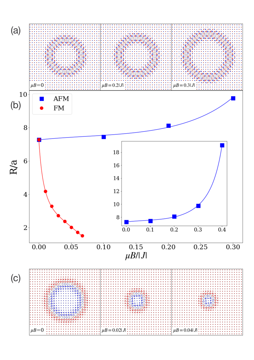
Both directions of the field perpendicular to the plane of the lattice are equivalent for a skyrmion in an AFM, but they lead to a different effect on a skyrmion in an FM. If the field is directed along the magnetization of the ferromagnet, it reduces the radius of the FM skyrmion. In the calculations presented here, this will be the direction of the applied magnetic field. If the field is directed in the opposite way, the size of the FM skyrmion increases and it easily becomes unstable with respect to a spiral structure. In the system studied numerically below, a field of just is sufficient to produce spiral structure. In experimental studies of skyrmions in FMs, the field is invariably directed along the magnetization of the ferromagnet.
III Methodology
The focus of the work presented here is an analysis of the various annihilation processes of skyrmions in AFMs and comparison with skyrmions in corresponding FMs. Also, the binding to and dissociation from a non-magnetic impurity is calculated. The energy as a function of all the variables representing degrees of freedom in the system, for example the angles describing the orientation of the magnetic moments, is referred to as the energy surface characterizing the system. We, however, use Cartesian coordinates of the magnetic moments and Lagrange multipliers to keep the magnitude of each magnetic moment constant in the calculations presented below. Metastable states are characterized by local energy minima on this energy surface and the stable state by the global minimum. A transition from one state to another is characterized by the minimum energy path (MEP) connecting the initial and final state minima. The MEP for a magnetic transition can be found using the geodesic nudged elastic band method.Bessarab2015 For large systems with many degrees of freedom it can be helpful to take advantage of previous knowledge of the saddle point and the shape of the MEP in its vicinity to reduce the computational effort.Lobanov2017 The activation energy for a transition can be estimated from the highest energy along the MEP. A maximum along the MEP corresponds to a first order saddle point on the energy surface.Bessarab13
The rate of a transitions in a magnetic system, such as a skyrmion annihilation process, can be estimated using the harmonic approximation to transition state theory (HTST) for magnetic systems.Bessarab2012 ; Bessarab13 The transition state is then taken to be a hyperplane going through the first order saddle point with normal vector pointing along the direction of the eigenvector corresponding to the negative eigenvalue of the Hessian at the saddle point, . The energy surfaces defined by the Hamiltonian in Eqn. (1) for an AFM material and the corresponding FM material coincide in the absence of an applied magnetic field. The activation energy for collapse is, therefore, the same for the two types of skyrmions if =0.
HTST predicts an Arrhenius-type rate law for transitions between magnetic states
The activation energy, , equals the energy at the (highest) maximum along the MEP minus the energy at the minimum corresponding to the initial state. The pre-exponential factor can be written asBessarab2012
| (3) |
where the factor is a ratio of determinants of the Hessian at the initial state minimum, , and at the saddle point, , i.e.
| (4) |
It is connected with the ratio of the entropy of the initial state and the transition state. The factor is connected with dynamics of the system and relates to the flux through the transition state. An explicit expression for the rate constant has previously been given in terms of eigenvalues and eigenvectors of the Hessian at the saddle point.Bessarab13 ; Bessarab2012 But, here is written in a basis invariant form as
| (5) |
where is the spin configuration at the saddle point and is the eigenvector corresponding to the negative eigenvalue of (a unit tangent vector to the MEP at the saddle point). This expression for is easier to evaluate numerically since it can be computed in spin-related basis without the evaluation of the eigenvectors of . Also, can then be interpreted without referring to the dividing surface. Indeed, is the value of the Hessian in the direction . The velocity is zero at since the gradient is zero, but the velocity at other points along the MEP is not zero, and in the vicinity of the saddle point the velocity is equal to times the distance from the saddle point. This means that the value of can be interpreted as the curvature of the energy surface at the saddle point in the direction of .
When several different transitions are possible from a given initial state, as for example the different annihilation processes considered here for the skyrmion, then the lifetime of the initial state can be obtained from the inverse of the sum of the rate constant of the various transitions . The lifetime of the skyrmion can thus be obtained from the sum of the rate of collapse (i.e. annihilation within the track) and escape through the boundary of the track. In the presence of an impurity, there are additional processes such as binding to the impurity and possible collapse there or detachment from the impurity. The time evolution of such a system where multiple possible transitions take place can be simulated using a kinetic Monte Carlo approach.
The harmonic approximation in HTST does not apply to degrees of freedom for which the energy is nearly constant. For example, a skyrmion can translate almost freely within the track for the system studied here. Such degrees of freedom need to be handled separately in the rate expression. They are often referred to as zero modes. An integration along these modes needs to be performed to obtain the corresponding entropy.Ivanov17 ; Bessarab2018 This gives the volume of the subspace corresponding to the zero-modes. As a result, has an additional factor , where , and , give the number of zero modes and the corresponding volumes at the saddle point and at the initial state minimum, respectively. We make here the assumption that the skyrmion can translate freely inside the track and also at the saddle point for collapse (i.e. there are two zero modes in both the initial state and transition state, nmin=nsp=2 ), while it can translate freely only in one direction at the saddle point for escape (nmin=2, nsp=1).
The transformation of exchange and DM interaction with simultaneous change of anisotropy and external magnetic field in accordance with Eqn. (2) and conserves the shape of energy surface. Therefore, the entropy factor is the same for the skyrmion collapse in AFM and the corresponding FM. However which is connected with the linearized Landau-Lifschitz equation in the neighborhood of the saddle point is different for skyrmions in AFMs and the corresponding FMs, as illustrated below.
IV Results
We now present results of numerical calculations for the model and parameter values specified above.
IV.1 Effect of applied field on skyrmion size
Fig. 1 shows how an applied magnetic field affects the radius of a skyrmion in the AFM and in the corresponding FM. The radius is defined here as the distance from the center to the region where the magnetic moments have no out of plane component. The size of the skyrmion changes in opposite ways in the two cases. While the radius of the skyrmion in the FM decreases when the field is directed against the moment in the center of the skyrmion, the radius of the skyrmion in AFM increases for either direction of the field perpendicular to the plane. The effect is larger for the skyrmion in FM and it becomes unstable in a field of =0.07 . However, the increase in the size of the skyrmion in AFM leads to increased stability.
IV.2 Rates of annihilation processes
Fig. 2 shows MEPs for the collapse of a skyrmion in AFM and the corresponding FM with and without applied magnetic field. Not only are the relaxed skyrmions equivalent in the two materials in the absence of an applied magnetic field, but this applies as well to the whole MEP. The activation energy for collapse is exactly the same. For parameters chosen here ( 31 meV, 5 meV, 11 meV, 8 ) the activation energy for collapse of the skyrmion is 124 meV when =0. This value of the magnetic moment in the 2D representation of the film could correspond to a 4 atomic layer film where each atom has a magnetic moment of 2 .
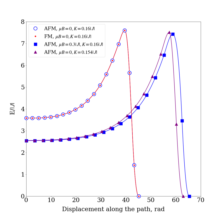
When a magnetic field is applied, the skyrmion in AFM becomes more stable and the MEP for collapse longer. Nearly the same effect on the path is obtained by modifying the anisotropy constant and setting the magnetic field to zero. For example, the application of a field of =0.3 is nearly equivalent to reducing the anisotropy constant from =0.16 to 0.154 in accordance with Eqn. (2). The total displacement along the path and activation energy for annihilation are quite similar in the two cases. The field increases the radius of the skyrmion in AFM by a third and the activation energy for annihilation increases by about a third making the skyrmion in AFM more stable.
The value of the pre-exponential factor of the rate constant for skyrmion collapse is for AFM and for the corresponding FM.
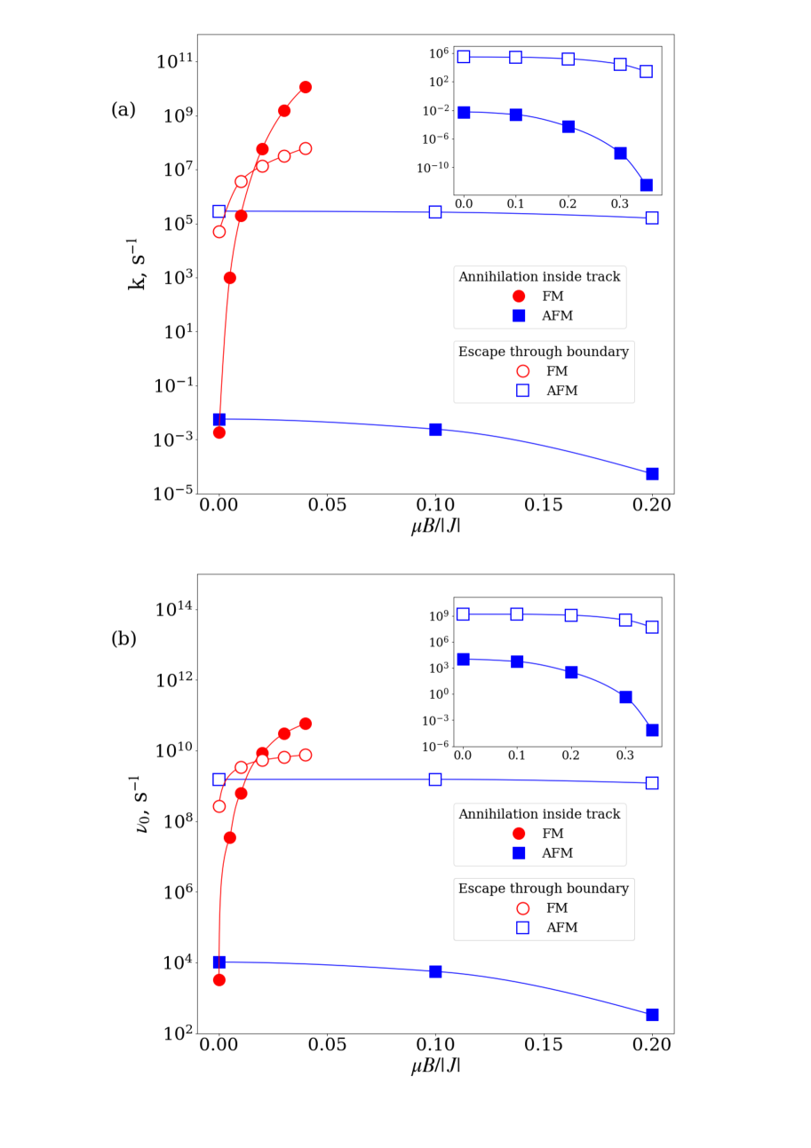
The effect of an applied field on the rate of collapse inside the track and escape through the boundary of the track can be seen in Fig. 3. For the FM, the rate of both mechanisms increases strongly with the field. While escape has higher rate constant for small field, a crossover between the two mechanisms occurs at a field of =0.02 and the rate constant for collapse inside the track becomes larger than escape through the edge for higher values of the field. The field has the opposite effect on the rate constants in the AFM as they become smaller when the field is increased, consistent with the increased activation energy shown in Fig. 2. However, the cause of the drop in the value of the rate constants is not only because of the increase in the activation energy but also a decrease in the pre-exponential factor, , as can be seen from Fig. 3(b). This reflects a decrease in the entropy of the transition state with respect to the entropy of the initial state. It can be understood from the fact that the larger the skyrmion is, the larger its vibrational entropy is. As the field increases, the skyrmion in AFM becomes larger, thus increasing the entropy of the initial state. But, at the transition state the skyrmion is reduced to a critical size that depends less on the applied field. So, the entropy of the transition state increases less with the field than the entropy of the initial state.
A more likely annihilation mechanism at zero magnetic field for this set of parameter values is an escape of the skyrmion through the edge of the track. Even if the relative number of sites adjacent to the edge and the number of sites in the interior of the track is taken into account, the probability of escape through the edge of the track is much more likely than collapse. This means that additional effort, such as insertion of material with other magnetic characteristics at the boundary, or pinning of skyrmions by defects such as a narrow strip with a different materials parameterStosic2017 are necessary to keep the skyrmion inside the track.
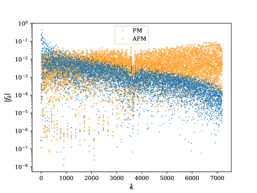
While the activation energy for collapse is exactly the same for a skyrmion in the AFM and in the corresponding FM when there is no applied field, the pre-exponential factor in the rate expression is different. The reason is that the Landau-Lifschitz dynamics of the skyrmion in the transition state is different in the two materials. Fig. 4 shows the contributions of the various eigenmodes : to the factor in the pre-exponential (see Eqn. (5)). The eigenvectors are numbered in increasing order of the corresponding eigenvalues. The calculated results show that small eigenvalues give the major contribution for the transition state for skyrmion collapse in the FM (note the logarithmic scale), whereas the full range of eigenvalues contributes in the AFM. As a result, the value of the pre-exponential factor for the collapse of a skyrmion in the AFM and the corresponding FM turn out to differ.
IV.3 Non-magnetic impurity
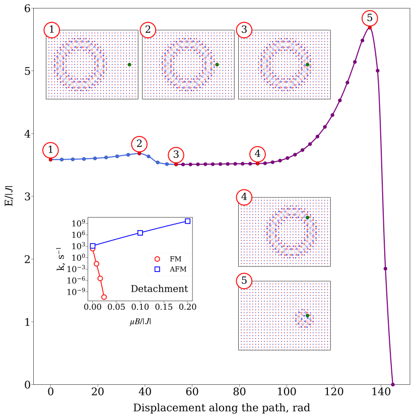
An important issue for practical applications of magnetic skyrmions is the effect of impurities in the magnetic material. The effect of a non-magnetic impurity on the stability and pinning of a skyrmion in FM has been presented previously. Uzdin18-ph_b Fig. 5 shows the minimum energy path for the attachment of a skyrmion in AFM to a non-magnetic substitutional atom and subsequent collapse of the skyrmion. There is a small activation energy barrier for attaching to the defect, but once that has been overcome the energy drops below that of a free skyrmion. The optimal configuration is obtained when the non-magnetic atom is located in the region where the magnetic moments have no out-of-plane component, see Fig. 5. This defines the optimal distance between the impurity and the center of the skyrmion. The skyrmion can rotate freely around the impurity as long as the distance to the impurity remains constant. This motion involves no change in the energy of the system (see the long stretch between points 3 and 4 in Fig. 5).
There is still a large probability that the skyrmion detaches from the impurity because the energy barrier is rather small. The impurity, however, also increases greatly the probability of collapse as the activation energy drops to a half compared to that of a free skyrmion, as can be seen by comparing Fig. 5 with Fig. 2. The impurity stabilizes the contracted skyrmion at the transition state more than the relaxed skyrmion in the initial state, thereby lowering the activation energy. Correspondingly, the lifetime drops if the skyrmion is bound to the impurity. An applied field has a beneficial effect for a skyrmion in the AFM by increasing the rate of detachment (see inset in Fig. 5) as well as by increasing the energy barrier for collapse, as shown in Fig. 2.
V Discussion
Skyrmions in AFMs and corresponding FMs can be described by similar energy surfaces. Without an applied magnetic field the energy surfaces coincide exactly. The inclusion of an applied magnetic field for the AFM material is equivalent to a change in in the anisotropy in the corresponding FM material without applied field. Therefore, the activation energy for annihilation and the entropy contribution to the pre-exponential factor in the transition rate is exactly the same for AFM and corresponding FM skyrmions. However, the rates are different because the dynamics through the transition state, given by the Landau-Lifschitz equation, is different. The calculated results presented here illustrate this for an example system. This result is in agreement with recently reported mean switching time by coherent rotation of AFM nanoparticles in the superparamagnetic limit, which have shown different pre-exponential factor for AFM and FM single-domain particles.Rozsa19
The effect of a non-magnetic impurity is found to be quite different for a skyrmion in the AFM than in the corresponding FM, especially in the presence of an applied field. Recently, dynamical modeling of the movement of the skyrmion inside a track and its collision with hole defects was reported.Silva19 Depending on the strength of the applied current and the type of collision, a skyrmion in an AFM can be captured, scattered or completely destroyed by the hole. Evidently, these phenomena are connected with the energy barriers and pre-exponential factors presented above.
The key question is whether it is possible to find an AFM where skyrmions are stable enough at room temperature. The equivalence of the energy surfaces for skyrmions in AFM and in the corresponding FM gives hope that this is possible, because stable skyrmions in FM materials at room temperature have been reported experimentally.soumyanarayanan2017 ; Fert17 ; Everschor-Sitte18 FM skyrmions that have been studied experimentally, even those which exist in ultra thin magnetic films on a surface of a heavy metal,Heinze2011 contain several magnetic atomic layers. If the thickness of the film is much less than the size of the skyrmion then the structure can be considered as a quasi 2D system. Such skyrmions are tubes with the same magnetic structure in each atomic layer.Sohn19 ; Vlasov20 In this approach, a column of magnetic moments is represented by a macrospin with effective parameters within the 2D model. Parameters of the Hamiltonian in Eqn. (1), such as and , are then to a first approximation proportional to the thickness of the magnetic film whereas the skyrmion radius and in-plane structure do not depend on the thickness. Evidently, if the sign of the exchange and DM interaction between magnetic moments in neighboring layers is changed as well as the directions of the magnetic moments, the same energy surface for AFM and FM is obtained as in the 2D case. For AFM, the vector should be considered instead of local moments, but the effective parameters of the Hamiltonian will, to first approximation, be proportional to the AFM film thickness as in the case of FM films.
Density functional theory (DFT) calculations have given estimates of the parameter characterizing the exchange interaction between nearest neighbor magnetic moments around 10 meV.Malottki2017 If the magnetic film contains several atomic layers, this parameter can be proportionally larger. As for FM materials, the parameter values for an AFM film scale with the thickness of the magnetic layer. The value of the exchange parameter , anisotropy parameter , and even magnetic moment (a macrospin representation) can be proportional to the number of magnetic layers. Note that the effective magnetic moment in the AFM case corresponds to the value of staggered magnetization L. Thus the effective values of the parameters in the 2D Hamiltonian Eqn. (1) can be much larger than values of the interactions between local magnetic moments calculated by the DFT method.Bessarab2018 ; Malottki2017 Note, however, that the DM interaction in a quasi-2D system is associated with the presence of a heavy metal with large spin orbit interaction and this effect decays rapidly away from the interface. The DM parameter is then not proportional to the thickness of the film. Nevertheless recent calculationsMa19 show that in an amorphous ferrimagnetic GdCo film on Pt, the skyrmion assumes a columnar configuration that extends uniformly across the film thickness of 10 nm despite having near zero DM interaction far away from the interface. Effective DM interaction is still enough to stabilize the skyrmion tube.
The properties of a skyrmion in an AFM is related here to the properties of a skyrmion in a corresponding FM by a transformation of the relevant parameters in the Hamiltonian and the orientation of the spins. Similar analysis can be carried out for other topological magnetic textures. For example, the properties of an antiskyrmion in a FM have been analyzed by spin transformation that converts it to a skyrmion in the FM and corresponding changes in the parameters in the Hamiltonian if there are no spin-orbit and spin-transfer torques. This means that the lifetime of the antiskyrmion is exactly the same as for the skyrmion if the DM vector is transformed accordingly. Moreover, by applying this transformation to the Landau-Lifshitz-Gilbert equation of motion one can predict the direction of the current for which the angle between current and antiskyrmion movement equals zero.Potkina19
The data that support the findings of this study are available from the corresponding author upon a reasonable request.
Acknowledgements.
This work was supported by the Icelandic Research Fund, the Research Fund of the University of Iceland, the Russian Foundation of Basic Research (grants RFBR 18-02-00267 and 19-32-90048) and the Foundation for the Advancement of Theoretical Physics and Mathematics “BASIS” under Grant No. 19-1-1-12-1.References
- (1) A. Fert, N. Reyren, and V. Cros, Nature Reviews Materials 2, 17031 (2017).
- (2) F. Büttner, I. Lemesh, and G. S. D. Beach, Scientific Reports 8, 4464 (2018).
- (3) K. Everschor-Sitte, J. Masell, R. Reeve, and M. Kläui, Journal of Applied Physics 124, 240901 (2018).
- (4) S. Heinze, K. von Bergmann, M. Menzel, J. Brede, A. Kubetzka, R. Wiesendanger, G. Bihlmayer, and S. Blügel, Nat. Phys. 7, 713 (2011).
- (5) S. Woo, K. Litzius, B. Kruger, M.-Y. Im, L. Caretta, K. Richter, M. Mann, A. Krone, R. M. Reeve, M. Weigand, P. Agrawal, I. Lemesh, M.-A. Mawass, P. Fischer, M. Klaui, and G. S. D. Beach, Nature Mater. 15, 501 (2016).
- (6) Y. Tokunaga, X. Z. Yu, J. S. White, H. M. Rnnow, D. Morikawa, Y. Taguchi, and Y. Tokura, Nature Communications 6, 7638 (2015).
- (7) V. M. Uzdin, M. N. Potkina, I. S. Lobanov, P. F. Bessarab, and H. Jónsson, J. Magn. Magn. Mat. 459, 236 (2018).
- (8) P. F. Bessarab, G. P. Müller, I. S. Lobanov, F. N. Rybakov, N. S. Kiselev, H. Jónsson, V. M. Uzdin, S. Blügel, L. Bergqvist, and A. Delin, Sci. Rep. 8, 3433 (2018).
- (9) R. Wiesendanger, Reviews Materials 1, 16044 (2016).
- (10) A. Soumyanarayanan, M. Raju, A. G. Oyarce, et al., Nature Materials 16, 898 (2017).
- (11) K. Litzius, I. Lemesh, B. Krüger, P. Bassirian, L. Caretta, K. Richter, F. Büttner, K. Sato, O. A. Tretiakov, J. Förster, R. M. Reeve, M. Weigand, I. Bykova, H. Stoll, G. Schütz, G. S. D. Beach, and M. Kläui, Nature Phys. 13, 170 (2017).
- (12) L. Smejkal, Y. Mokrousov, B. Yan, and A. H. MacDon- ald, Nature Communications 14, 242 (2018).
- (13) O. Gomonay, T. Jungwirth, and J. Sinova, Phys. Rev. Lett. 117, 017202 (2016).
- (14) A. K. Nayak, V. Kumar, T. Ma, P. Werner, E. Pippel, R. Sahoo, F. Damay, U. K. Rößler, C. Felser, and S. S. P. Parkin, Nature 548, 561 (2017).
- (15) W. Legrand, D. Maccariello, F. Ajejas, S. Collin, A. Vecchiola, K. Bouzehouane, N. Reyren, V. Cros, and A. Fert, Nature Materials 19, 34 (2020).
- (16) L. Caretta, M. Mann, F. Büttner, K. Ueda, B. Pfau, C. M. Günther, P. Hessing, A. Churikova, C. Klose, M. Schneider, E. D., C. Marcus, B. D., B. K., S. Eisebitt, and G. S. D. Beach, Nature Nanotechnology 13, 1154 (2018).
- (17) S. Woo, K. M. Song, X. Zhang, Y. Zhou, M. Ezawa, X. Liu, S. Finizio, J. Raabe, N. J. Lee, S.-I. Kim, S.-Y. Park, Y. Kim, J.-Y. Kim, D. Lee, O. Lee, J. W. Choi, B.-C. Min, H. C. Koo, and J. Chang, Nature Communications 9, 959 (2018).
- (18) P. M. Buhl, F. Freimuth, S. Blügel, and Y. Mokrousov, Phys. Status Solidi RRL 11, 1700007 (2017).
- (19) A. N. Bogdanov and D. A. Yablonskii, Sov. Phys. JETP 68, 101 (1989); Sov. Phys. JETP 68, 142 (1989).
- (20) A. N. Bogdanov and A. A. Shestakov, Low Temp. Phys. 25, 76 (1999).
- (21) A. N. Bogdanov, U. K. Rösler, M. Wolf and K.-H. Müller, Phys. Rev. B 66, 214410 (2002).
- (22) L. Shen, J. Xia, G. Zhao, X. Zhang, M. Ezawa, O. A. Tretiakov, X. Liu and Y. Zhou, Phys. Rev. B 98, 134448 (2018).
- (23) X. Liang, G. Zhao, L. Shen, J. Xia, L. Zhao, X. Zhang and Y. Zhou, Phys. Rev. B 100, 144439 (2019).
- (24) R. Khoshlahni, A. Qaiumzadeh, A. Bergman and A. Brataas, Phys. Rev. B 99, 054423 (2019).
- (25) R. Keesman, M. Raaijmakers, A. E. Baerends, G. T. Barkema, and R. A. Duine, Phys. Rev. B 94, 054402 (2016).
- (26) X. Zhang, Y. Zhou, and M. Ezawa, Scientific Reports 6, 24795 (2016).
- (27) C. Jin, C. Song, J. Wang, and Q. Liu, Applied Physics Letters 109, 182404 (2016).
- (28) J. Barker and O. A. Tretiakov, Phys. Rev. Lett. 116, 147203 (2016).
- (29) P. Bessarab, D. Yudin, D. Gulevich, P. Wadley, M. Titov, and O. A. Tretiakov, Phys. Rev. B 99, 140411 (2019).
- (30) I. S. Lobanov, H. Jónsson, and V. M. Uzdin, Phys. Rev. B 94, 174418 (2016).
- (31) P. F. Bessarab, V. M. Uzdin, and H. Jónsson, Comput. Phys. Commun. 196, 335 (2015).
- (32) I. S. Lobanov, M. N. Potkina, H. Jónsson, and V. M. Uzdin, Nanosystems: Physics, Chemistry, Mathematics 8, 586 (2017).
- (33) P. F. Bessarab, V. M. Uzdin and H. Jónsson, Zeitschrift fur Physikalische Chemie 227, 1543 (2013).
- (34) P. F. Bessarab, V. M. Uzdin, and H. Jónsson, Phys. Rev. B 85, 184409 (2012).
- (35) A. Ivanov, P. F. Bessarab, V. M. Uzdin and H. Jónsson, Nanoscale 9, 13320 (2017).
- (36) W. T. Coffey, D. A. Garanin, and D. J. McCarthy, Advances in Chemical Physics 117, 483 (2001).
- (37) L. Desplat, D. Suess, J.-V. Kim, and R. Stamp, Phys. Rev. B 98, 134407 (2018).
- (38) D. Stosic, J. Mulkers, B. Van Waeyenberge, T. B. Ludermir, and M. V. Milosević, Phys.Rev.B 95, 214418 (2017).
- (39) V. M. Uzdin, M. N. Potkina, I. S. Lobanov, P. F. Bessarab, and H. Jónsson, Physica B 549, 6 (2018).
- (40) L. Rózsa, S. Selzer, T. Birk, U. Atxitia, and U. Nowak, Phys. Rev. B 100, 064422 (2019).
- (41) R. L. Silva, R. C. Silva, A. Pereira, and W. A. Moura-Melo, J. Phys.: Condens. Matter 31, 225802 (2019).
- (42) H. R. O. Sohn, S. M. Vlasov, V. M. Uzdin, A. O. Leonov, and I. I. Smalyukh, Phys. Rev. B 100, 104401 (2019).
- (43) S. M. Vlasov, V. M. Uzdin, and A. O. Leonov, J. Phys.: Condens. Matter 32, 185801 (2020).
- (44) S. von Malottki, B. Dupé, P. F. Bessarab, A. Delin, and S. Heinze, Scientific Reports 7, 12299 (2017).
- (45) C. T. Ma, Y. Xie, H. Sheng, A. Ghosh, and S. J. Poon, Scientific Reports 9, 9964 (2019).
- (46) M. N. Potkina, I. S. Lobanov, O. A. Tretiakov, H. Jónsson, and V. M. Uzdin, arxiv.org/abs/1906.06383 (2019).