Anti-parity-time Symmetry in Passive Nanophotonics
Abstract
Parity-time (PT) symmetry in non-Hermitian optical systems promises distinct optical effects and applications not found in conservative optics. Its counterpart, anti-PT symmetry, subscribes another class of intriguing optical phenomena and implies complementary techniques for exotic light manipulation. Despite exciting progress, so far anti-PT symmetry has only been realized in bulky systems or with optical gain. Here, we report an on-chip realization of non-Hermitian optics with anti-PT symmetry, by using a fully-passive, nanophotonic platform consisting of three evanescently coupled waveguides. By depositing a metal film on the center waveguide to introduce strong loss, an anti-PT system is realized. Using microheaters to tune the waveguides’ refractive indices, striking behaviors are observed such as equal power splitting, synchronized amplitude modulation, phase-controlled dissipation, and transition from anti-PT symmetry to its broken phase. Our results highlight exotic anti-Hermitian nanophotonics to be consolidated with conventional circuits on the same chip, whereby valuable chip devices can be created for quantum optics studies and scalable information processing.
1 Introduction
Optical realizations of non-Hermitian Hamiltonians possessing parity-time (PT) symmetry[1, 2] promise innovative techniques such as enhanced sensing at exceptional points [3, 4], unidirectional light propagation [5, 6], and PT-symmetric laser [7, 8]. Exploiting the mathematical equivalence between quantum Schrodinger and electromagnetic paraxial equation, PT-symmetric optical systems have been constructed by balancing gain and dissipation [9, 10, 11, 12, 13, 14]. Its counterpart, anti-PT symmetry, represents another striking class of non-Hermitian physics [15, 16, 17]. Unlike PT-symmetry accompanied by real eigenvalues, anti-PT systems have purely imaginary eigenvalues, which give rise to surprising effects and extraordinary utilities [15]. Also, anti-PT can be realized without optical gain, which has been a source of noise and/or significant device overhead in PT systems. These, and other advantages, make anti-PT symmetry effects more accessible in practice and provide the prospect of mass integration with other optical components for scalable applications [10, 11, 12, 13, 14]. Thus far, effects of anti-PT symmetry have been observed in cold atoms [17, 18], electrical circuits [19], and very recently integrated photonics with balanced loss and gain induced by Brillouin scattering [16].
In this work, we report an all-passive realization of anti-PT optics on a versatile nanophotonic platform of thin-film lithium niobate on insulator (LNOI). Using three waveguides with carefully-engineered lateral coupling and loss, we observe the anti-PT symmetry and its transition to a broken phase via thermal-optical tuning. Incorporating it in an imbalanced Mach-Zehnder interferometer, we further achieve exotic synchronized amplitude modulation and phase-controlled dissipation. All of our experimental results are in good agreement with the numeric solutions of a non-Hermitian Hamiltonian, which affirms the anti-PT effects observed. Unlike previous realizations, here the system is constructed using purely passive optics without any optical gain [17, 16, 20]. Furthermore, the whole structure is monolithic etched using standard LNOI fabrication recipes, by which a variety of other optical elements, such as electro-optical modulators[21, 22], frequency converters[23, 24], filters, and photon sources [25], can be integrated on the same chip. This highlights the prospect of creating exotic chips that consolidate coherent, non-Hermitian, and anti-Hermitian optical circuits, for applications in areas of photonic computing, communications, sensing, and so on.
2 Structure design and Model
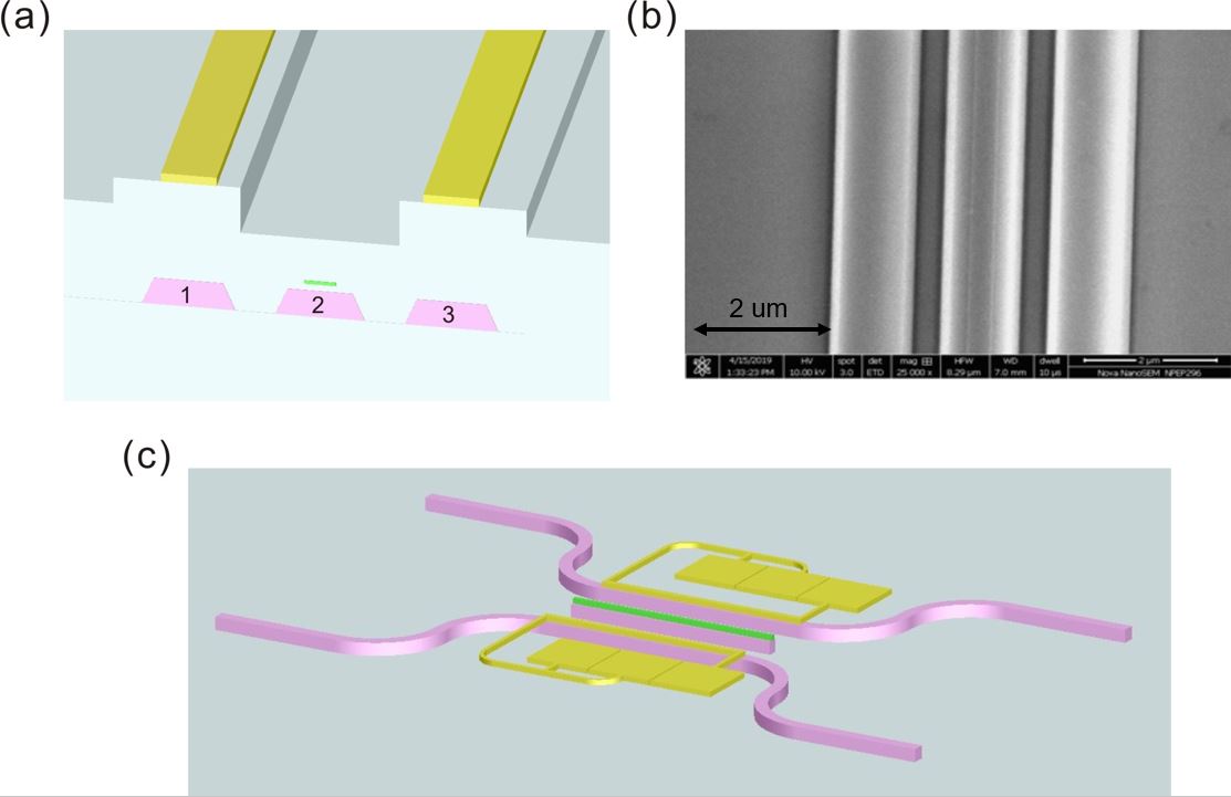
A schematic of the anti-PT nanophotonic circuit is depicted in Fig. 1, which implements the proposal in Ref. [26, 12]. It consists of three evanescently coupled waveguides, labeled as , , and . They are fully etched by ion milling on a Z-cut lithium niobate thin film bonded on silicon oxide above a silicon substrate. The top widths of three waveguides are measured to be 870, 820 and 870 nm, respectively, and their heights are all 400 nm. Waveguide is cladded with a chromium strip to introduce strong propagation loss, which is measured at an amplitude decay rate of 1080 dB/cm. The details of device nanofabrication and characterization are presented in the Supplementary Material.
The system’s wave dynamics is described by following coupled mode equations under the solwly varying envelope approximation [26]:
| (1) |
where () is the mode amplitude in Waveguide . is the lateral coupling rate between neighboring waveguides. is the dissipation rate of the Waveguide 2 mode induced by the chromium strip. and are each the relative propagation constants, thus the effective detuning, of the waveguide modes.
To realize an effective anti-PT system, the dissipation in Waveguide 2 must be predominantly large, i.e., . Under this condition, adiabatic elimination can be applied to reduce the equations of motion as
| (2) |
where the effective Hamiltonian
| (3) |
with . It is clear that is anti-Hamitian that anti-commutes with the parity-time operators and , i.e., . Here is the effective “imaginary” coupling strength between Waveguide 1 and 3, which is distinct from typical PT systems where the coupling constants are real [27, 28, 29].
Unlike Hermitian Hamiltonians, gives non-trivial eigen solutions. When , there are two eigenvalues
| (4) |
which are purely imaginary. The corresponding eigenstates are
| (5) |
with ). Thus, both eigenstates correspond to the two waveguides sharing the equal amplitude, but with different relative phase. They are orthogonal with each other only when , in which case experiences propagation decay at rate , but is lossless. Hence, only could survive after sufficient propagation length. The same implies synchronized output and equal splitting of input power that are robust against the structure’s parameter errors such as the waveguide length, loss, and coupling. When , the two eigenstates are not orthogonal with each other, with unequal propagation losses differed by .
On the other hand, when , the eignvalues are no longer purely imaginary, becoming
| (6) |
The system is then in a broken phase of the PT anti-symmetry, whose eigenstates are
| (7) |
with . Unlike the previous case, now the distribution of optical power is asymmetrical over the two waveguides. Under this circumstance, this system exhibits non-reciprocal behaviors, and the optical power will mostly remain in the incident waveguide when is large [26].
On our chips, two microheaters are deposited 1.5 m above Waveguide 1 and 3, respectively, to precisely tune via thermo-optic effects while inducing only negligible loss. To utilize the highest thermo-optic coefficient of LNOI, fundamental transverse-magnetic (TM) modes are employed for all waveguides. To further increase the tunability, a trench is also etched above the center waveguide to partially block thermal flow. These allow us to flexibly tune without affecting other system parameters, including the waveguide mode profiles and coupling strength. With a maximum of 200 mW electric power applied to either microheater, we are able to sweep and observe the phase transition from the symmetry to broken phase, and vice versa; see Supplementary Material.
3 Results and discussion
In our setup, a polarized beam at 1550 nm is coupled into a fundamental TM mode of Waveguide 3 though an objective lens (C330-TMD-C from Thorlabs) as the input. The output light, from Waveguide 1 or 3, is collected by a lensed fiber (OZ optics) placed on a translation stage, and subsequently measured using a power meter. A varied electric current is applied to either of the two microheaters to tune .
In the first experiment, increasing current is applied to the microheater above Waveguide 1, which leads to increased optical power at the output of both waveguides, signifying a decreased detuning. As the applied heating power reaches 135 mW, the output optical power from the two waveguides is maximized simultaneously. At this point, is close to zero. Afterwards, the current is switched to the microheater on Waveguide 3. The output power of both waveguides plummets as expected, due to an increased . The output power from Waveguide 1 is minimized when the heating power reaches 201 mW. The experimental results are summarized in Fig. 2(a), where each waveguide’ output power is plotted as a function of the applied heating power. In the figure, the negative and positive heating power correspond to the current applied to the microheaters on Waveguide 1 and 3, respectively. From these data, the overall coupling efficiency, attributed to the losses of the fiber coupler, the objective lens to the waveguide, and the waveguides to the lensed fiber, is extract to be -14.8 dB by fitting the data in Fig. 2. The inter-waveguide coupling strength and detuning can also be extracted, while the induced dissipation rate is measured using a cut-back method; see Fig. S3 and Table. S1 in the Supplementary Material for details.
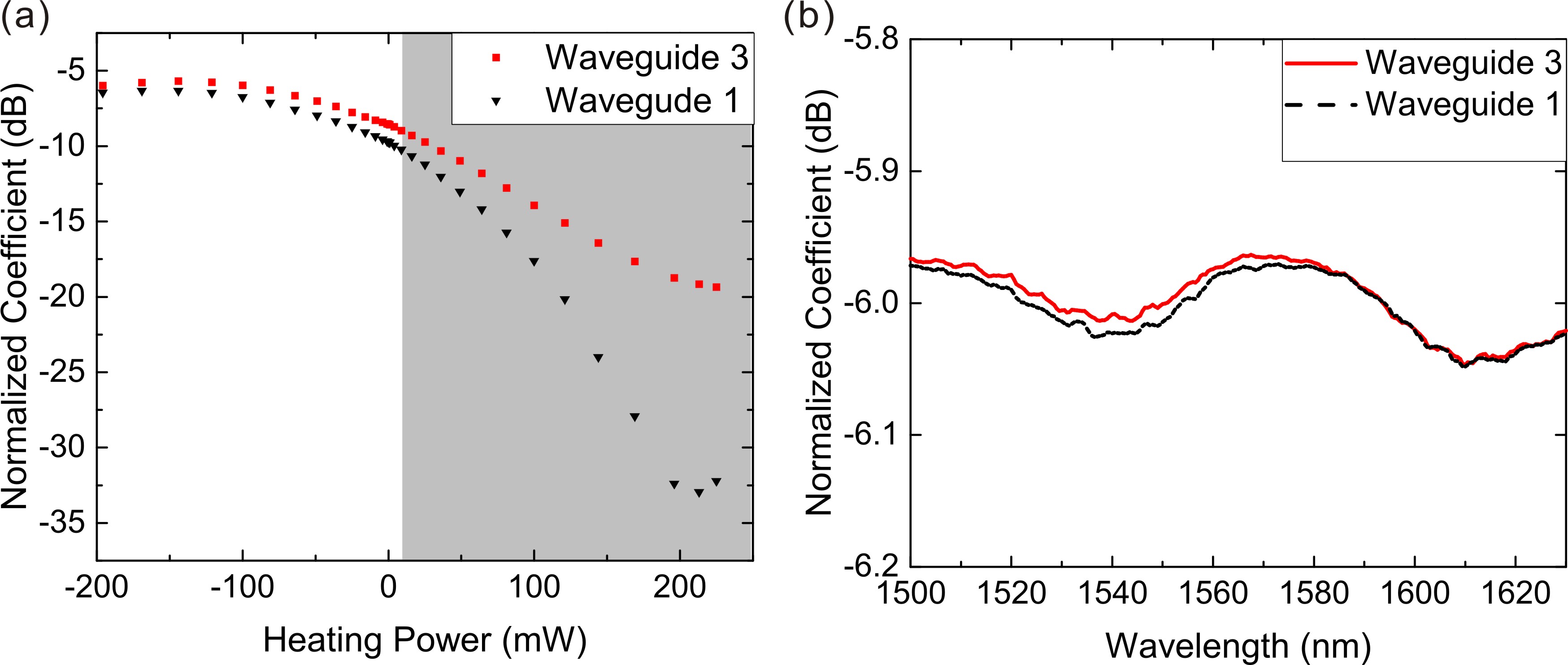
As shown in Fig. 2, the output power from the two waveguides is almost equal when the effective detuning approaches zero. It thus invites to construct a 50:50 beamsplitter on chip using the present anti-PT structure. Distinct to directional coupling [30], such equal beam splitting realized under anti-PT symmetry is not sensitive to the inter-waveguide coupling strength, the waveguide length, its propagation loss, or the optical wavelength. To demonstrate this, Waveguide 1 is applied with 135 mW heating power to bring the effective detuning close to zero. Then, the output power from Waveguide 1 and 3 are measured as the input laser wavelength is swept over a spectral range of 130 nm, as allowed by our laser tuning range. The results are shown in Fig. 2(b), where very flat, equal power splitting is observed over the entire spectrum, with less than deviation. As such equal splitting only requires ( is the waveguide length), it greatly boosts the tolerance of nanofabrication errors as compared with a coherent-optical circuit; see Fig. S5 in the Supplementary Material. Furthermore, this operational bandwidth is much wider than typically achievable with beam-splitters based on multimode interference or directional coupling [31]. It implies practical values for applications with ultra-broadband signals and could prove useful for mass chi-integration.
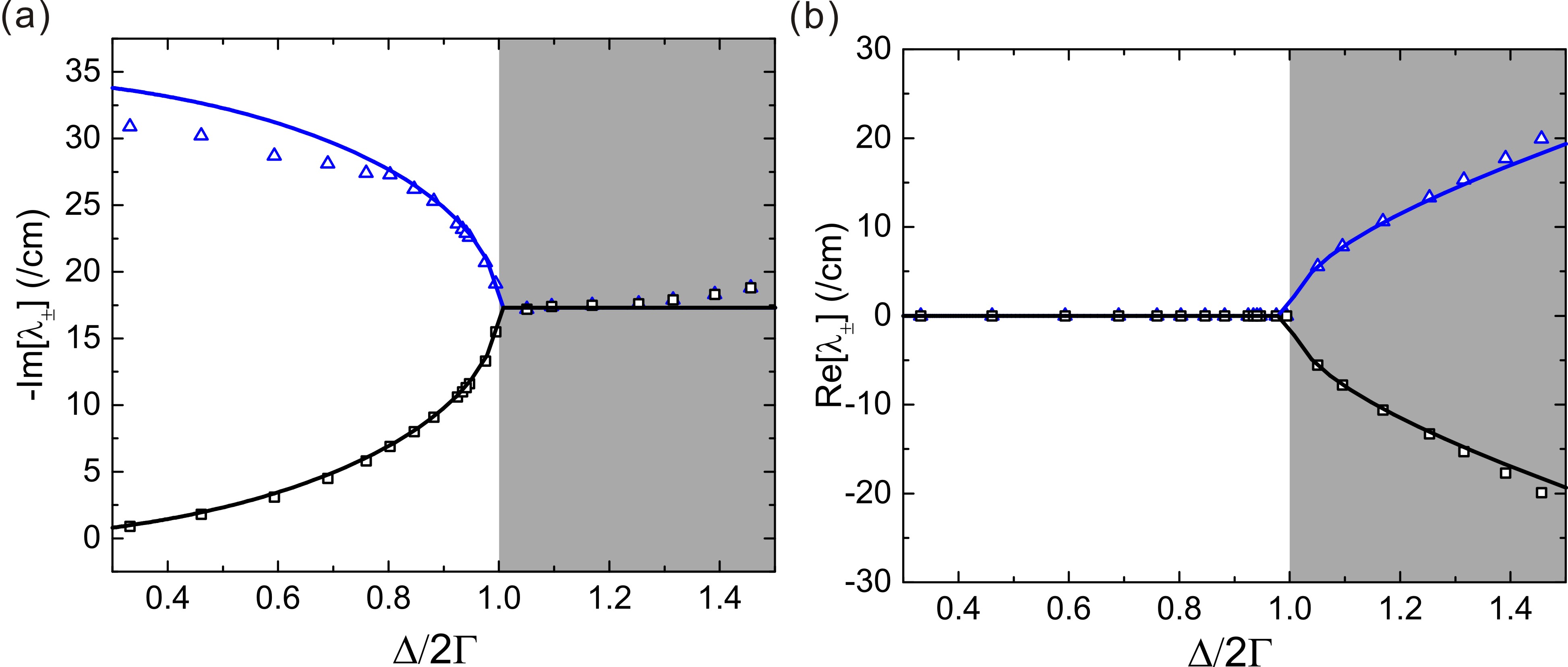
Using the coupling efficiency from the previous fitting results, the coupling strength and the effective detuning can be evaluated for each heating power by Eqs. (S3) and (S4) in Supplementary Material. As expected, is nearly independent of the applied heating power, while increases linearly with it, as shown in Fig. S3 and S4 of Supplementary Material. Then the eigenstates and eigenvalues of the effective Hamiltonian (3) can be calculated at each heating power point. The results are given in Fig. 3, where the imaginary and real parts of the eigenvalues are plotted as functions of . On the same figure, the theoretical results using cm-1, obtained by averaging over the various heating power applied, and cm-1mW-1, as determined by the fitting in Fig. S4 of Supplementary Material. As shown, there is a clear phase transition occurring at the exceptional point of , as predicted by Eqs.(4) and (6). When , the two eigenvalues are purely imaginary, whose amplitude difference increases to nearly 30/cm as the detuning is decreased to . Meanwhile, the real wave vectors for the two eignmodes remain the same. When , in contrast, the two eigenstates share the same dissipation rate but have different wave vectors.
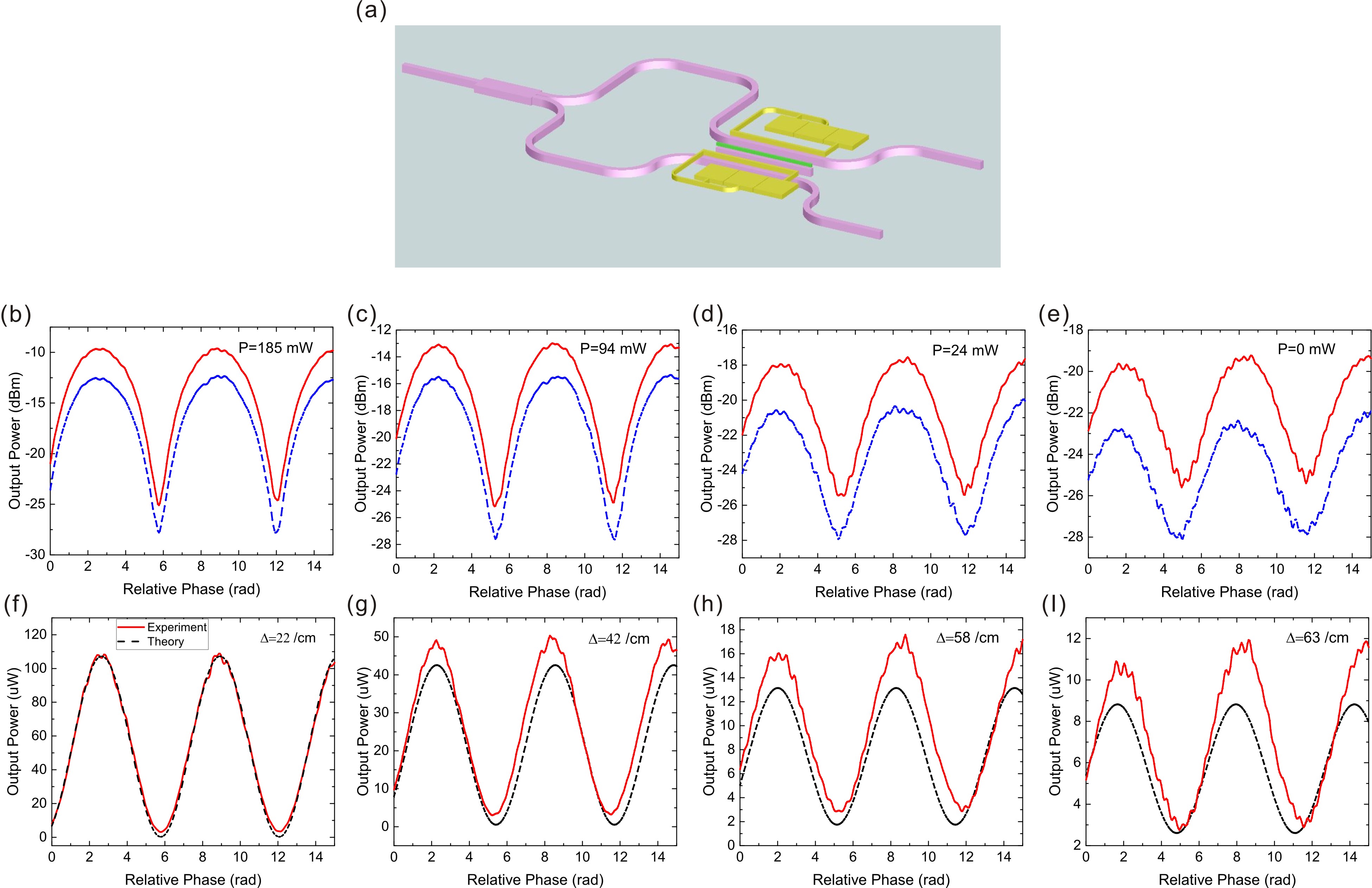
Another distinct feature is the output power synchronization: with two inputs of equal amplitude, the output power of the two waveguides is always equal, regardless of the relative phase between the two inputs. This holds irrespective of whether the system is in the anti-PT symmetry or its broken phase. On the other hand, the total output power is not conserved and sensitive to the relative phase. Such a phenomenon is in direct contrast to that in coherent-optical couplers describable by Hermitian Hamiltonians, where the total output power is conserved but its distribution over the outputs is sensitive to the input relative phase. This effect thus complements what coherent optics can offer, which may find utilities applications in areas of sensing[4], measurement, optical modulation, and lasers. To observe those effects, we fabricate a LNOI circuit incorporating the anti-PT structure into an imbalanced interferometer, as shown in Fig. 4(a). An input laser is first split equally into two parts upon a multimode interferometer. They are then each guided along two waveguides of the same cross section but different path length, before fed into an input. Their relative phase acquired before the anti-PT structure is given by , with being the waveguides’ refractive index, the path length difference, and the laser wavelength. In our structure, m, so that by scanning from 1544 nm to 1550 nm, is swept over 16 radians nearly linearly with . Meanwhile, other system parameters, such as and , remain practically unchanged to allow observing the effects caused only by the relative phase variation.
The results are presented in Figs. 4(b-e), where the output power from the two waveguides is measured individually as , thus , is swept under diffphase between subsequent peaks is . As seen, in all cases, the two outputs are always equal in power except for a constant factor ( 2 dB), which is likely attributed to the difference in the waveguide propagation and coupling loss in the two outputs, caused by, e.g., stitching errors during nanofabrication. The total output power, on the other hand, oscillates with , where a high 15 dB extinction is achieved with 185 mW heating power applied to the microheater above Waveguide 1, as seen in Fig. 4(b). These results demonstrate clear effects of synchronized amplitude modulation and phase-controlled dissipation.
To understand the above phenomena, we simulate the system dynamics using Hamiltonian (3), with cm-1, the coupling efficiency, and other parameters extracted from the previous measurements in Fig.2. As a comparison, Figs. 4(f-i) plot the measured and simulated output power from the Waveguide 3. In all four figures, the only fitting parameter used is the baseline detuning , as it is extremely sensitive to the waveguide’s cross section and cannot be otherwise determined. Rather, is best fitted to be cm-1 when the heating power is 185 mW, as shown in 4(f). For other heating settings, is calculated directly using its linear dependence of the applied heating power. As shown, in all cases, the experimental and simulation results agree fairly well. In Fig. 4(f), , so that the system is in anti-PT symmetry. The output power thus experiences the strongest loss when the two inputs are in phase and the least loss when they are out of phase. This is expected because in the limit, each of the two cases correspond to and , whose eigenvalues differ by . Thus their losses through the structure are significantly different, giving rise to the high extinction as is varied. As increases, the propagation loss difference in the two cases decreases, so is the extinction. In Fig. 4(i), when , the system is significantly into the broken phase, for which the extinction drops to 5 dB.
4 Conclusion
In conclusion, We have observed anti-PT symmetry and its transition into a broken phase using an all-passive, nanophotonic platform. By thermal tuning, we observed striking phenomena such as power equal splitting, synchronized amplitude modulation, and phase-controlled dissipation under anti-PT symmetry, as well as their behaviors as the system evolves passing the exceptional point and into the broken phase. The good agreement between our experimental results with the predictions of a non-Hermitian Hamiltonian affirms the anti-PT effects observed, which are not found in other conservative or PT-symmetric optics. They could be used to construct synchronized modulators, novel optical interferometers, and nontrivial logical gates, such as exclusive-OR phase gate. By replacing the thermal tuning with electronic tuning to control the relative phase, one might also realize exotic electro-optical interfaces as well.
As the anti-PT structure is realized entirely using purely passive optics and monolithic etched on lithium niobate thin films, hybrid chips are ready to be developed incorporating Hermitian and anti-Hermitian circuits for exotic functionalities. Our work complements the exciting progress made recently in lithium niobate nanophotonics, as such electro-optical modulators, frequency converters, filters, and photon sources. By consolidating a variety of other elements and circuits on the same chip, exceptional optical devices and systems can be developed for photonic computing, communications, sensing, and so on.
Funding Information
This research is supported in part by National Science Foundation (Awards: 1806523, 1806519, and EFMA-1741693).
Disclosures
Disclosures. The authors declare no conflicts of interest.
Supplemental Documents
See Supplement 1 for supporting content.
References
- [1] A. MOSTAFAZADEH, “Pseudo-hermitian representation of quantum mechanics,” \JournalTitleInternational Journal of Geometric Methods in Modern Physics 07, 1191–1306 (2010).
- [2] Bender, C. M., and S. Boettcher, “Real spectra in non-hermitian hamiltonians having pt symmetry,” \JournalTitlePhys. Rev. Lett. 80, 5243–5246 (1998).
- [3] H. Hodaei, A. U. Hassan, S. Wittek, H. Garcia-Gracia, R. El-Ganainy, D. N. Christodoulides, and M. Khajavikhan, “Enhanced sensitivity at higher-order exceptional points,” \JournalTitleNature 548, 187–191 (2017).
- [4] Y.-H. Lai, Y.-K. Lu, M.-G. Suh, Z. Yuan, and K. Vahala, “Observation of the exceptional-point-enhanced sagnac effect,” \JournalTitleNature 576, 65–69 (2019).
- [5] Z. Lin, H. Ramezani, T. Eichelkraut, T. Kottos, H. Cao, and D. N. Christodoulides, “Unidirectional invisibility induced by -symmetric periodic structures,” \JournalTitlePhys. Rev. Lett. 106, 213901 (2011).
- [6] L. Feng, Y.-L. Xu, W. S. Fegadolli, M.-H. Lu, J. E. B. Oliveira, V. R. Almeida, Y.-F. Chen, and A. Scherer, “Experimental demonstration of a unidirectional reflectionless parity-time metamaterial at optical frequencies,” \JournalTitleNature Materials 12, 108–113 (2013).
- [7] H. Hodaei, M.-A. Miri, M. Heinrich, D. N. Christodoulides, and M. Khajavikhan, “Parity-time–symmetric microring lasers,” \JournalTitleScience 346, 975–978 (2014).
- [8] L. Feng, Z. J. Wong, R.-M. Ma, Y. Wang, and X. Zhang, “Single-mode laser by parity-time symmetry breaking,” \JournalTitleScience 346, 972–975 (2014).
- [9] R. El-Ganainy, K. Makris, D. Christodoulides, and Z. Musslimani, “Theory of coupled optical pt-symmetric structures,” \JournalTitleOpt. Lett 32, 2201–2229 (2007).
- [10] R. El-Ganainy, K. G. Makris, M. Khajavikhan, Z. H. Musslimani, S. Rotter, and D. N. Christodoulides, “Non-hermitian physics and pt symmetry,” \JournalTitleNature Physics 14, 11–19 (2018).
- [11] L. Feng, R. El-Ganainy, and L. Ge, “Non-hermitian photonics based on parity-time symmetry,” \JournalTitleNature Photonics 11, 752–762 (2017).
- [12] J. Wen, X. Jiang, L. Jiang, and M. Xiao, “Parity-time symmetry in optical microcavity systems,” \JournalTitleJournal of Physics B: Atomic, Molecular and Optical Physics 51, 222001 (2018).
- [13] V. V. Konotop, J. Yang, and D. A. Zezyulin, “Nonlinear waves in -symmetric systems,” \JournalTitleRev. Mod. Phys. 88, 035002 (2016).
- [14] S. K. Özdemir, S. Rotter, F. Nori, and L. Yang, “Parity-time symmetry and exceptional points in photonics,” \JournalTitleNature Materials 18, 783–798 (2019).
- [15] Y. Li, Y.-G. Peng, L. Han, M.-A. Miri, W. Li, M. Xiao, X.-F. Zhu, J. Zhao, A. Alù, S. Fan, and C.-W. Qiu, “Anti–parity-time symmetry in diffusive systems,” \JournalTitleScience 364, 170–173 (2019).
- [16] F. Zhang, Y. Feng, X. Chen, L. Ge, and W. Wan, “Synthetic anti-pt symmetry in a single microcavity,” \JournalTitlePhys. Rev. Lett. 124, 053901 (2020).
- [17] Y. Jiang, Y. Mei, Y. Zuo, Y. Zhai, J. Li, J. Wen, and S. Du, “Anti-parity-time symmetric optical four-wave mixing in cold atoms,” \JournalTitlePhys. Rev. Lett. 123, 193604 (2019).
- [18] P. Peng, W. Cao, C. Shen, W. Qu, J. Wen, L. Jiang, and Y. Xiao, “Anti-parity-time symmetry with flying atoms,” \JournalTitleNature Physics 12, 1139–1145 (2016).
- [19] Y. Choi, C. Hahn, J. W. Yoon, and S. H. Song, “Observation of an anti-pt-symmetric exceptional point and energy-difference conserving dynamics in electrical circuit resonators,” \JournalTitleNature Communications 9, 2182 (2018).
- [20] A. Guo, G. J. Salamo, D. Duchesne, R. Morandotti, M. Volatier-Ravat, V. Aimez, G. A. Siviloglou, and D. N. Christodoulides, “Observation of pt-symmetry breaking in complex optical potentials,” \JournalTitlePhys. Rev. Lett. 103, 093902 (2009).
- [21] C. Wang, M. Zhang, X. Chen, M. Bertrand, A. Shams-Ansari, S. Chandrasekhar, P. Winzer, and M. Loncar, “Integrated lithium niobate electro-optic modulators operating at cmos-compatible voltages,” \JournalTitleNature 562, 101–104 (2018).
- [22] M. Jin, J.-Y. Chen, Y. M. Sua, and Y.-P. Huang, “High-extinction electro-optic modulation on lithium niobate thin film,” \JournalTitleOptics Letters 44, 1265–1268 (2019).
- [23] J.-Y. Chen, Z.-H. Ma, Y. M. Sua, Z. Li, C. Tang, and Y.-P. Huang, “Ultra-efficient frequency conversion in quasi-phase-matched lithium niobate microrings,” \JournalTitleOptica 6, 1244–1245 (2019).
- [24] J. Lu, J. B. Surya, X. Liu, A. W. Bruch, Z. Gong, Y. Xu, and H. X. Tang, “Periodically poled thin-film lithium niobate microring resonators with a second-harmonic generation efficiency of 250,000 /,” \JournalTitleOptica 6, 1455–1460 (2019).
- [25] Z. Ma, J.-Y. Chen, Y. M. Sua, Z. li, C. Tang, and Y.-P. Huang, “Efficient photon pair generation in thin-film lithium niobate microring resonators,” \JournalTitleOSA Quantum 2.0 Conference (2020 forthcoming).
- [26] F. Yang, Y.-C. Liu, and L. You, “Anti-pt symmetry in dissipatively coupled optical systems,” \JournalTitlePhys. Rev. A 96, 053845 (2017).
- [27] C. E. Rüter, K. G. Makris, R. El-Ganainy, D. N. Christodoulides, M. Segev, and D. Kip, “Observation of parity-time symmetry in optics,” \JournalTitleNature Physics 6, 192–195 (2010).
- [28] B. Peng, S. K. Özdemir, F. Lei, F. Monifi, M. Gianfreda, G. L. Long, S. Fan, F. Nori, C. M. Bender, and L. Yang, “Parity-time-symmetric whispering-gallery microcavities,” \JournalTitleNature Physics 10, 394–398 (2014).
- [29] L. Chang, X. Jiang, S. Hua, C. Yang, J. Wen, L. Jiang, G. Li, G. Wang, and M. Xiao, “Parity-time symmetry and variable optical isolation in active-passive-coupled microresonators,” \JournalTitleNature Photonics 8, 524–529 (2014).
- [30] G. F. R. Chen, J. R. Ong, T. Y. L. Ang, S. T. Lim, C. E. Png, and D. T. H. Tan, “Broadband silicon-on-insulator directional couplers using a combination of straight and curved waveguide sections,” \JournalTitleScientific Reports 7, 7246 (2017).
- [31] A. Ortega-Monux, L. Zavargo-Peche, A. Maese-Novo, I. Molina-Fernandez, R. Halir, J. G. Wanguemert-Perez, P. Cheben, and J. H. Schmid, “High-performance multimode interference coupler in silicon waveguides with subwavelength structures,” \JournalTitleIEEE Photonics Technology Letters 23, 1406–1408 (2011).
sample