Dynamical low-noise microwave source for cold-atom experiments
Abstract
The generation and manipulation of ultracold atomic ensembles in the quantum regime require the application of dynamically controllable microwave fields with ultra-low noise performance. Here, we present a low-phase-noise microwave source with two independently controllable output paths. Both paths generate frequencies in the range of GHz MHz for hyperfine transitions in 87Rb. The presented microwave source combines two commercially available frequency synthesizers: an ultra-low-noise oscillator at GHz and a direct digital synthesizer for radiofrequencies. We demonstrate a low integrated phase noise of µrad in the range of Hz to kHz and fast updates of frequency, amplitude and phase in sub-µs time scales. The highly dynamic control enables the generation of shaped pulse forms and the deployment of composite pulses to suppress the influence of various noise sources.
I Introduction
Atom interferometers belong to today’s most precise sensors with broad applications for navigation, geodesy, time keeping as well as fundamental research. An atom interferometric measurement relies on the determination of the phase difference between two atomic states. In many cases, these atomic states are hyperfine levels in alkali atoms. For magnetic field sensing or frequency measurements, the hyperfine transitions can be directly driven with microwave radiation. For inertial sensors, such as gravimeters, accelerometers or gyroscopes, the hyperfine transitions can be driven by a two-photon optical transition with a microwave frequency detuning. In analogy to optical interferometers, microwave pulses driving these transitions act as beam splitters or mirrors between the atomic states. Phase noise of the microwave is directly converted into fluctuations of the measured interferometer phase. The rapidly increasing sensitivity in the field of atom interferometry poses increasing demands on the noise characteristics of the employed microwave sources. This is specifically the case for interferometric experiments with squeezed atomic samples Pezzè et al. (2018), which are not restricted by the Standard Quantum Limit (SQL) and are thus even more sensitive to the microwave’s phase and intensity noise.
In our experiments, we create entangled many-particle states in Bose-Einstein condensates by spin-changing collisions Lücke et al. (2011, 2014); Kruse et al. (2016); Lange et al. (2018). The microwave source serves four purposes: The initial preparation of all atoms in a specific hyperfine/Zeeman level, the dressing of Zeeman levels to activate spin-changing collisions, the manipulation of the states in an interferometric protocol, and the final rotation of the state for detection and state analysis. These tasks pose the following requirements on the design of the microwave source.
Variable frequency. For the preparation of the atoms, a sequence of microwave pulses with variable frequencies is desired.
Low phase noise. The high-fidelity manipulation of the atomic states demands a microwave with small phase fluctuations, as the phase serves as the reference for all atomic measurements Chen et al. (2012a). In our atom interferometric applications, the fluctuation of the microwave’s phase during the interferometric cycle is directly converted into fluctuations of the quantity of interest. For the future, we would like to operate the interferometers with microwave pulses of µs length and free evolution times of several tens of milliseconds, such that a fluctuating phase is relevant from Hz up to kHz. We aim at an interferometric phase resolution close to the Heisenberg limit , with the number of employed particles . The generation of entangled states is currently performed with atoms. A Heisenberg-limited resolution for such atom numbers of course requires the suppression of more technical noise sources. For example, we were able to improve the so far limiting detection noise to single-atom resolution for several hundred atoms Hüper et al. (2020). To ensure that the microwave phase noise is not limiting, it must be suppressed to a value below µrad.
Low intensity noise. For tomographic measurements of the entangled states, the microwave should perform stable couplings between the employed spin levels. To resolve the expected patterns with single-particle resolution, the microwave must offer spin rotations with a relative intensity stabilization that is stable for a typical measurement time on the order of one hour.
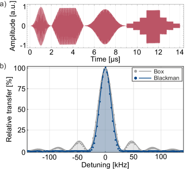
Fast dynamical adjustments. The spin preparation benefits from short microwave pulses that are executed closely after each other. Short pulses bear the advantage of a low sensitivity to small microwave detunings due to an increasingly broad peak in Fourier space. This is, however, not sufficient for an advantageous spectral distribution. Short pulses can lead to many side peaks in the Fourier spectrum if they are simple box pulses. This may lead to an unwanted population of neighboring levels. The entire width of the spectrum can be drastically reduced by applying tailored pulse shapes instead of rectangular pulses. Pulse shaping requires a microwave amplitude modulation below the microsecond scale and the short pulse durations can only be realized by a source with sufficient microwave power. Furthermore, some interferometry and state tomography schemes are based on a fast and reproducible adjustment of the microwave’s phase. The combined modulation of frequency, phase and intensity enables the application of composite pulses Dunning et al. (2014), which can be designed to suppress the sensitivity to various technical noise sources.
Intensity-stable dressing field. Finally, we wish to apply an independent microwave dressing field during the experimental sequence to achieve precise control of individual energy levels. This application is particularly sensitive to fluctuations of the microwave field’s intensity because the desired energy shift depends linearly on the power of the microwave signal. Hence, a stable microwave power is desired for quasi-adiabatic state preparation by ramped microwave dressing, as we use it for the generation of highly entangled twin-Fock states Luo et al. (2017); Anders et al. (2021). Typically, for a G magnetic field, we shift the level via microwave dressing by Hz. For high-accuracy adiabatic generation, we require maximal frequency fluctuations of mHz over typical ramping times of a few seconds, corresponding to microwave intensity fluctuations of mHzHz%. In summary, our experiments require a microwave source with amplitude, frequency and phase modulation in the microsecond range, low phase fluctuations and an independent, stable microwave dressing field.
There exist commercial frequency generators in the microwave regime that allow for a dynamical adjustment of frequency and amplitude. However, these systems typically lack an independent adjustment of the phase or suffer from slow update speeds in the millisecond range. There are important scientific developments towards microwave sources with minimal phase fluctuations, which serve as local oscillators for microwave clocks Boudot, Guérandel, and de Clercq (2009); Lipphardt et al. (2009); Fortier et al. (2012); François et al. (2015); Abdel Hafiz et al. (2017). However, for these applications, a fast dynamical adjustment is not intended.
Publications reporting on low-phase-noise microwave sources that are designed for a fast dynamical adjustment of frequency, phase and amplitude are rare. Chen et al. Chen et al. (2012b) present a microwave source for spin-squeezing experiments in 87Rb based on a self-built nonlinear transmission line that is phase-locked to a MHz atomic clock. Controllability of parameters in the range of µs to µs is achieved by a single-sideband modulator and a direct digital synthesizer (DDS). The obtained integrated phase noise amounts to mrad in the Hz to kHz bandwidth. Morgenstern et al. Morgenstern et al. (2020) demonstrated a microwave source at GHz, controlled by a field programmable gate array (FPGA), to realize a microwave dressing in sodium Bose-Einstein condensates. The source features parameter changes within µs. The phase stability is not specified, as it is not critical for their application.
Here, we present a microwave source with low integrated phase noise of µrad in the Hz to kHz bandwidth. The microwave frequency is derived from a commercial GHz source and a DDS, which controls frequency, amplitude and phase with high accuracy. An interplay of components from the open-source hardware family Sinara 111Information about the Sinara ecosystem can be found under https://sinara-hw.github.io. and the control system ARTIQ Bourdeauducq et al. (2021) enables single-parameter updates within ns. The setup does not comprise self-built components and fits into a 19 inch rack. The source consists of two independent DDS-controlled channels, which can be applied for two-photon transitions or for a background dressing field. The described microwave source thus offers the ability to control atomic spins with highest fidelity on short time scales, and the simultaneous application of a dressing field.
The article is organized as follows. Section II covers the system design and the installed components. In Section III, we characterize the system regarding phase noise and dynamic features. Finally, we summarize our findings and outline the future application of the system in our spin-squeezing experiments.
II System Design
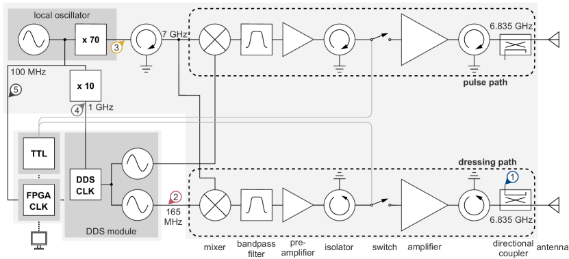
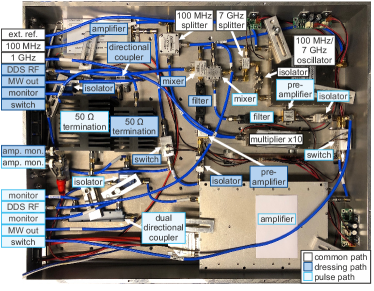
Figure 1 shows a schematic of the final design of our microwave source and Fig. 2 the corresponding picture. The basic idea is to combine the low phase noise of a multiplied crystal oscillator with the dynamic properties of an FPGA-controlled DDS. Our design presents an easy-to-assemble setup with commercial components Meyer-Hoppe (2023) and very low phase noise and our implementation opens up highly dynamical features.
An ultra-low-phase-noise oscillator Wenzel MXO-PLD is used as local oscillator. It provides a stable microwave frequency at GHz through integrated multiplication of a fundamental MHz oscillation, which is accessible through an additional output. The oscillator also has the option of an external reference, which is currently not used in our setup.
For the dynamic parameter change of the radiofrequency component, we employ the commercially available DDS module Urukul Kasprowicz et al. (2022). This module contains four Analog Devices AD9910 222The product page of the AD9910 DDS can be found under https://www.analog.com/en/products/ad9910.html?doc=AD9910.pdf. DDS chips and associated radiofrequency components for adequate filtering, variable attenuation and switching. Control over the DDS module is achieved by the FPGA module Kasli. A digital I/O module DIO_BNC offers the possibility for triggered execution and controlling additional components such as microwave switches. All three modules are part of the Sinara ecosystem and can be bought commercially as a preconfigured device. The DDS module features four independently controllable radiofrequency channels with an adjustable frequency of up to MHz. All channels share a common reference of GHz, given by the local oscillator’s MHz multiplied by 10. The GHz frequency reference allows for direct clocking of the DDS channels. Compared to the case of indirect clocking, where the GHz clock is generated by internally multiplying the local oscillator’s MHz in the DDS module, we measured an improved phase noise performance of µrad. For the microwave source, two of these DDS outputs operate the two individual microwave output stages. In addition to frequency setting, the amplitude and also the phase offset for absolute phase control can be defined (Tab. 1).
| Parameter | Bits | Range | Resolution |
|---|---|---|---|
| Frequency | 32 | MHz | mHz |
| Amplitude | 14 | % | % |
| Phase offset | 16 | rad | µrad |
For our 87Rb atoms, we have to apply frequencies at with a tuning range of MHz to account for the employed magnetic fields. In both output channels, the frequency is reached by mixing a shared local oscillator (LO) signal at GHz with an individual DDS frequency of MHz. The lower sideband after the mixing presents the desired resonant frequency at . The two output stages for pulses and dressing include final amplifiers to obtain powers of W and W, respectively.
For the mixing process, a Marki Microwave SSB-0618 single sideband mixer and a Mini Circuits ZMX-8GLH mixer are used for the pulse path and the dressing path, respectively. The single sideband mixer in the more critical channel is used to lower the unwanted peaks at the local oscillator frequency and the upper sideband at . A narrow Wainwright WBCQV3 bandpass filter with a passband of 20 MHz and attenuation for frequencies of MHz from the center frequency enables the reduction of the LO and the upper sideband level in both channels.
Directly after mixing, the pulse and dressing paths measure maximally dBm and dBm, respectively. Low-noise pre-amplifiers Mini Circuits ZX60-83LN-S+ raise the signal to the desired dBm input for the high-power amplifiers.
Because the internal power switch of the DDS channel only offers a maximal attenuation of dB, the source is equipped with additional power switches Mini Circuits ZFSWA2-63DR+ with ns rise/fall time and an attenuation of dB. The employed switches – designed for frequencies up to GHz – are a cost-effective solution, coming with disadvantages of larger insertion loss and reflections. The insertion loss is compensated by the pre-amplifiers. Isolators prevent unwanted back reflections in general, and are installed in front of the switches and the antenna, as well as behind the local oscillator.
For the amplification of the pulse path, a water-cooled W amplifier Microwave Amps AM43 is employed. The amplifier in the dressing path is a Kuhne KU PA 640720-10 A with an output power of W. The pulse path contains a dB dual directional coupler RF-Lambda RFDDC2G8G30 for monitoring the output power and the power that is reflected from the antenna. A dB directional coupler MCLI C39-20 after the dressing amplifier allows for monitoring the dressing power. For addressing the atoms, the microwave frequency is coupled to free space by an impedance-matched, open-ended waveguide. In the following section, the performance of the described microwave source is evaluated.
III Characterization
III.1 Spectral properties
First of all, we examine the spectrum of the microwave source to quantify the suppression of disturbing frequencies, that could drive unwanted transitions, resulting in decreased efficiency of the state preparation. Figure 3 shows the spectrum of our microwave source for both the dressing path and the pulse path with a chosen output frequency of GHz. The spectrum was recorded with a Rohde&Schwarz FSWP8 phase noise and spectrum analyzer.
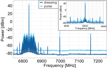
The unwanted frequency contributions close to the main peak are caused by the DDS, while the two peaks at GHz and GHz are residuals of the local oscillator frequency and the upper sideband of the mixing process. Both of these peaks are suppressed by the narrow bandpass filter: For the pulse path, the local oscillator and the upper sideband peak are suppressed by dB and dB, respectively. For the dressing path, the suppression is dB and dB due to the different choice for the frequency mixer.
Because of the bandpass filters, the peak power slightly varies with the frequency of the microwave source by about dB in the relevant frequency range of GHz MHz and dB for GHz MHz. The small effect in the relevant range can be calibrated and the power can be adjusted by the ARTIQ software.
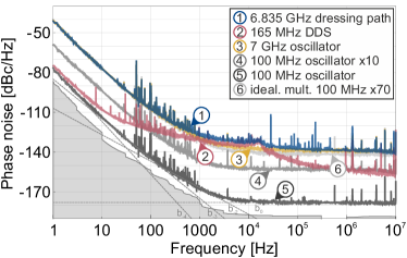
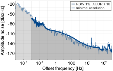
Furthermore, we evaluate the phase noise , where is the one-sided spectral density of phase fluctuations and is the offset frequency from the carrier Ferre-Pikal et al. (2009). A low phase noise is desired for a high-fidelity state preparation and manipulation (Section I). Figure 4 shows the phase noise contributions for the microwave source, measured for an output frequency of GHz with the Rohde&Schwarz FSWP8. The colors of the lines correspond to different measurement points in the system, as visualized in Fig. 1.
The phase noise of the two microwave output signals is very similar, although they follow different amplification paths. The overall phase noise is limited by the DDS for frequencies from kHz up to kHz and by the local oscillator for all other frequencies. It is below dBc/Hz above Hz and below dBc/Hz for frequencies greater than kHz, and approaches a floor of dBc/Hz at high frequencies. The small peak at kHz stems from residual DDS noise Calosso, Olaya, and Rubiola (2020) and may originate from power supply noise. For both paths, we obtain a favorably small integrated phase noise of in the important range of Hz to kHz (Section I), which provides the central figure of merit of the constructed microwave source.
With a reference connected to the local oscillator, the long-term stability could be improved and therefore the phase noise for small frequency offsets could be decreased.
The amplitude (AM) noise of the presented microwave source is also measured and shown in Fig. 5. Because the amplitude noise is important also for very low offset frequencies and measurements in that range have a very long duration, high sensitivity limits had to be accepted as a consequence. Hence, the amplitude noise of the microwave source can only be given as an upper bound. For the bandwidth of µHz (measurement duration of one hour) to kHz, it evaluates to an integrated AM noise of % and therefore an intensity noise of %. It is thus in the desired order of magnitude to achieve Heisenberg-limited resolution.
III.2 Dynamic features
The dynamics of the microwave source is controlled by the ARTIQ system which is connected to a computer via an optical fiber and a LAN switch. The commands are implemented on the computer in the Python programming language but compiled and executed on the FPGA hardware, thereby allowing for a minimal timing resolution of ns. The code generating our experiments is available online333The gitlab repository of the control program is avaiable under https://gitlab.projekt.uni-hannover.de/iqo-artiq/artiq/public/arbitrary-pulses-spinor-bec.
The AD9910 DDS chip in the Urukul module also provides a bit random-access memory (RAM) to retrieve and output different waveforms that are designed by the user. It is possible to program frequency, amplitude, phase or polar (amplitude and phase) nonlinear ramps with a step width of ns into one out of eight profiles. For our purposes, time-dependent amplitude functions are used to reduce the effective Fourier width (Fig. 6) and the coupling to unwanted transitions. For the dressing scenario, adiabatic power ramps ensure that the system remains in the desired dressed state.
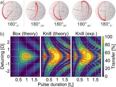
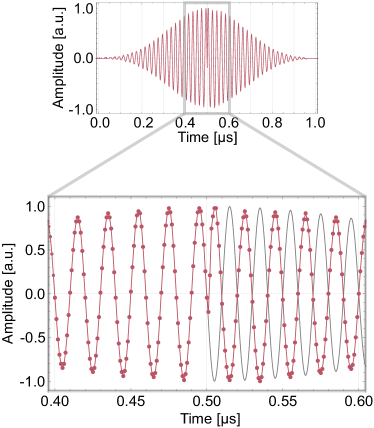
The phase of the microwave signal is deterministically referenced to the local oscillator phase in a coherent way. This allows for composite pulse techniques, where one single pulse is replaced by a sequence of pulses with different phases, amplitudes and durations to reduce the impact of various noise sources Dunning et al. (2014); Levitt (1986). Figure 7 shows a so-called Knill sequence Ryan, Hodges, and Cory (2010) that reduces sensitivity to both intensity and frequency fluctuations. Besides the phase setting, it is advantageous for this technique to execute the pulses in quick succession to avoid unwanted fluctuations during the dead times. Updates of parameters like frequency or phase require ns in our implementation. This corresponds to a minimal pulse duration of a few µs when two totally different pulses should be executed in direct succession. Start and end times of pulses on different DDSs have to be equal or at least differ by ns if they are on the same Urukul module. Two separate modules could, however, be operated completely independent without this delay. Figure 8 finally shows an amplitude-shaped pulse where the phase of the radiofrequency is altered halfway using one common profile instead of two distinguished pulses. This example demonstrates the highly dynamical phase control.
IV Conclusion
In summary, we have presented a microwave source with sub-µs update speed and adjustable phase.
Composite pulses and nonlinear ramps can be delivered while maintaining a low integrated phase noise of µrad.
The experimental sequences are implemented on a computer with Python and the ARTIQ software, allowing for a nanosecond timing resolution.
The microwave source is based on commercially available components and adaptable to other atomic species than 87Rb.
The design with two independently controllable paths opens up various possibilities such as the addressing of two-photon processes and the Rabi coupling to a dressed state.
Acknowledgements.
We thank É. Wodey for his support regarding the ARTIQ implementation. We acknowledge financial support from the Deutsche Forschungsgemeinschaft (DFG, German Research Foundation) – Project-ID 274200144 – SFB 1227 DQ-mat within the project A02, under Germany’s Excellence Strategy – EXC-2123 QuantumFrontiers – 390837967 and from the European Union through the QuantERA grant 18-QUAN-0012-01 (CEBBEC). F.A. and B.M.-H. acknowledge support from the Hannover School for Nanotechnology (HSN). B.M-H. acknowledges the use of the QuTiP Johansson, Nation, and Nori (2013) Python toolbox for Bloch sphere illustrations.Conflict of Interest Statement
The authors have no conflicts to disclose.
Author contributions
Bernd Meyer-Hoppe: Conceptualization (lead); Investigation (lead); Software (supporting); Visualization (lead); Writing - Original Draft Preparation (equal); Writing - Review & Editing (equal). Maximilian Baron: Investigation (supporting); Software (lead); Visualization (supporting); Writing – Review & Editing (equal). Christophe Cassens: Investigation (supporting); Writing – Review & Editing (equal). Fabian Anders: Conceptualization (supporting); Supervision (supporting); Writing – Review & Editing (equal). Alexander Idel: Conceptualization (supporting); Writing – Review & Editing (equal). Jan Peise: Conceptualization (supporting); Supervision (supporting); Writing – Review & Editing (equal). Carsten Klempt: Conceptualization (lead); Funding Acquisition (lead); Supervision (lead); Writing – Original Draft Preparation (equal); Writing – Review & Editing (equal).
Data Availability
The data that support the findings of this study are available from the corresponding author upon reasonable request.
References
- Pezzè et al. (2018) L. Pezzè, A. Smerzi, M. K. Oberthaler, R. Schmied, and P. Treutlein, “Quantum metrology with nonclassical states of atomic ensembles,” Rev. Mod. Phys. 90 (2018).
- Lücke et al. (2011) B. Lücke, M. Scherer, J. Kruse, L. Pezzé, F. Deuretzbacher, P. Hyllus, O. Topic, J. Peise, W. Ertmer, J. Arlt, L. Santos, A. Smerzi, and C. Klempt, “Twin matter waves for interferometry beyond the classical limit,” Science 334, 773–776 (2011).
- Lücke et al. (2014) B. Lücke, J. Peise, G. Vitagliano, J. Arlt, L. Santos, G. Tóth, and C. Klempt, “Detecting multiparticle entanglement of Dicke states,” Phys. Rev. Lett. 112, 155304 (2014).
- Kruse et al. (2016) I. Kruse, K. Lange, J. Peise, B. Lücke, L. Pezzè, J. Arlt, W. Ertmer, C. Lisdat, L. Santos, A. Smerzi, and C. Klempt, “Improvement of an atomic clock using squeezed vacuum,” Phys. Rev. Lett. 117, 143004 (2016).
- Lange et al. (2018) K. Lange, J. Peise, B. Lücke, I. Kruse, G. Vitagliano, I. Apellaniz, M. Kleinmann, G. Tóth, and C. Klempt, “Entanglement between two spatially separated atomic modes,” Science 360, 416–418 (2018).
- Chen et al. (2012a) Z. Chen, J. G. Bohnet, J. M. Weiner, and J. K. Thompson, “General formalism for evaluating the impact of phase noise on bloch vector rotations,” Phys. Rev. A 86, 032313 (2012a).
- Hüper et al. (2020) A. Hüper, C. Pür, M. Hetzel, J. Geng, J. Peise, I. Kruse, M. A. Kristensen, W. Ertmer, J. Arlt, and C. Klempt, “Number-resolved preparation of mesoscopic atomic ensembles,” New Journal of Physics 23, 113046 (2020).
- Dunning et al. (2014) A. Dunning, R. Gregory, J. Bateman, N. Cooper, M. Himsworth, J. A. Jones, and T. Freegarde, “Composite pulses for interferometry in a thermal cold atom cloud,” Phys. Rev. A 90, 033608 (2014).
- Luo et al. (2017) X.-Y. Luo, Y.-Q. Zou, L.-N. Wu, Q. Liu, M.-F. Han, M. K. Tey, and L. You, “Deterministic entanglement generation from driving through quantum phase transitions,” Science 355, 620–623 (2017) .
- Anders et al. (2021) F. Anders, A. Idel, P. Feldmann, D. Bondarenko, S. Loriani, K. Lange, J. Peise, M. Gersemann, B. Meyer-Hoppe, S. Abend, N. Gaaloul, C. Schubert, D. Schlippert, L. Santos, E. Rasel, and C. Klempt, “Momentum entanglement for atom interferometry,” Physical Review Letters 127, 140402 (2021).
- Boudot, Guérandel, and de Clercq (2009) R. Boudot, S. Guérandel, and E. de Clercq, “Simple-design low-noise NLTL-based frequency synthesizers for a CPT Cs clock,” IEEE Transactions on Instrumentation and Measurement 58, 3659–3665 (2009).
- Lipphardt et al. (2009) B. Lipphardt, G. Grosche, U. Sterr, C. Tamm, S. Weyers, and H. Schnatz, “The stability of an optical clock laser transferred to the interrogation oscillator for a cs fountain,” IEEE Transactions on Instrumentation and Measurement 58, 1258–1262 (2009).
- Fortier et al. (2012) T. M. Fortier, C. W. Nelson, A. Hati, F. Quinlan, J. Taylor, H. Jiang, C. W. Chou, T. Rosenband, N. Lemke, A. Ludlow, D. Howe, C. W. Oates, and S. A. Diddams, “Sub-femtosecond absolute timing jitter with a 10 GHz hybrid photonic-microwave oscillator,” Applied Physics Letters 100, 231111 (2012).
- François et al. (2015) B. François, C. E. Calosso, M. Abdel Hafiz, S. Micalizio, and R. Boudot, “Simple-design ultra-low phase noise microwave frequency synthesizers for high-performing Cs and Rb vapor-cell atomic clocks,” Review of Scientific Instruments 86, 094707 (2015).
- Abdel Hafiz et al. (2017) M. Abdel Hafiz, G. Coget, P. Yun, S. Guérandel, E. de Clercq, and R. Boudot, “A high-performance raman-ramsey Cs vapor cell atomic clock,” Journal of Applied Physics 121, 104903 (2017).
- Chen et al. (2012b) Z. Chen, J. G. Bohnet, J. M. Weiner, and J. K. Thompson, “A low phase noise microwave source for atomic spin squeezing experiments in 87Rb,” Review of Scientific Instruments 83, 044701 (2012b).
- Morgenstern et al. (2020) I. Morgenstern, S. Zhong, Q. Zhang, L. Baker, J. Norris, B. Tran, and A. Schwettmann, “A versatile microwave source for cold atom experiments controlled by a field programmable gate array,” Review of Scientific Instruments 91, 023202 (2020).
- Note (1) Information about the Sinara ecosystem can be found under https://sinara-hw.github.io.
- Bourdeauducq et al. (2021) S. Bourdeauducq, whitequark, R. Jördens, D. Nadlinger, Y. Sionneau, and F. Kermarrec, “Artiq (version 6),” Zenodo (2021), 10.5281/zenodo.6619071.
- Meyer-Hoppe (2023) B. Meyer-Hoppe, “Microwave source component list,” 10.25835/n3l98dkt (2023).
- Kasprowicz et al. (2022) G. Kasprowicz, T. Harty, S. Bourdeauducq, R. Jördens, D. Allcock, D. Nadlinger, J. Britton, A. Sotirova, and D. Nowicka, “Urukul – open-source frequency synthesizer module for quantum physics,” Int. J. Electron. Telecommun. 68 (2022).
- Note (2) The product page of the AD9910 DDS can be found under https://www.analog.com/en/products/ad9910.html?doc=AD9910.pdf.
- Rubiola (2009) E. Rubiola, Phase noise and frequency stability in oscillators (Cambridge University Press, 2009).
- Ferre-Pikal et al. (2009) E. S. Ferre-Pikal, J. Vig, J. Camparo, L. Cutler, L. Maleki, W. Riley, S. Stein, C. Thomas, F. Walls, and J. White, “IEEE standard definitions of physical quantities for fundamental frequency and time metrology — random instabilities,” IEEE Std Std 1139-2008 , c1–35 (2009).
- Calosso, Olaya, and Rubiola (2020) C. E. Calosso, A. C. C. Olaya, and E. Rubiola, “Phase-noise and amplitude-noise measurement of DACs and DDSs,” IEEE Trans. Ultrason. Ferroelectr. Freq. Control 67, 431–439 (2020).
- Note (3) The gitlab repository of the control program is avaiable under https://gitlab.projekt.uni-hannover.de/iqo-artiq/artiq/public/arbitrary-pulses-spinor-bec.
- Levitt (1986) M. H. Levitt, “Composite pulses,” Progress in Nuclear Magnetic Resonance Spectroscopy 18, 61 – 122 (1986).
- Ryan, Hodges, and Cory (2010) C. A. Ryan, J. S. Hodges, and D. G. Cory, “Robust decoupling techniques to extend quantum coherence in diamond,” Phys. Rev. Lett. 105, 200402 (2010).
- Johansson, Nation, and Nori (2013) J. Johansson, P. Nation, and F. Nori, “Qutip 2: A python framework for the dynamics of open quantum systems,” Comp. Phys. Comm. 184, 1234–1240 (2013).
Copyright (2023) Bernd Meyer-Hoppe, Maximilian Baron, Christophe Cassens, Fabian Anders, Alexander Idel, Jan Peise, Carsten Klempt. This article is distributed under a Creative Commons Attribution (CC BY) License. It may be found at DOI:10.1063/5.0160367.