Skyrmion Dynamics and Transverse Mobility: Skyrmion Hall Angle Reversal on 2D Periodic Substrates with dc and Biharmonic ac Drives
Abstract
We numerically examine the dynamics of a skyrmion interacting with a two-dimensional periodic substrate under dc and biharmonic ac drives. We show that the Magnus force of the skyrmion produces circular orbits that can resonate with the ac drive and the periodicity of the substrate to create quantized motion both parallel and perpendicular to the dc drive. The skyrmion Hall angle exhibits a series of increasing and/or decreasing steps along with strongly fluctuating regimes. In the phase locked regimes, the skyrmion Hall angle is constant and the skyrmion motion consists of periodic orbits encircling an integer number of obstacles per every or every other ac drive cycle. We also observe phases in which the skyrmion moves at with respect to the driving direction even in the presence of damping, a phenomenon called absolute transverse mobility that can exhibit reentrance as a function of dc drive. When the biharmonic ac drives have different amplitudes, in the two directions we find regimes in which the skyrmion Hall angle shows a sign reversal from positive to negative, as well as a reentrant pinning effect in which the skyrmion is mobile at low drives but becomes pinned at higher drives. These behaviors arise due to the combination of the Magnus force with the periodic motion of the skyrmions, which produce Shapiro steps, directional locking, and ratchet effects.
pacs:
75.70.KwDomain structure (including magnetic bubbles and vortices) and 05.45.XtSynchronization; coupled oscillators and 47.57.-sComplex fluids and colloidal systems and 74.25.WxVortex pinning (superconductivity)1 Introduction
There are a number of systems that can be modeled effectively as a particle moving over a two-dimensional (2D) periodic substrate under a dc drive. Such systems include vortices in type-II superconductors interacting with 2D pinning arrays Harada96 ; Reichhardt97 ; Martin99 ; Reichhardt08a ; Gutierrez09 ; Sadovskyy17 ; Ge18 , colloids moving over optical trap arrays Korda02 ; MacDonald03 ; Bohlein12 ; Vanossi12 ; Hasnain13 or periodically patterned surfaces McDermott13a ; Tierno09 ; Loehr18 ; Cao19 ; Stoop20 , and models of atomic friction Tekic05 ; Vanossi13 . Typically, when an additional ac drive is applied to these systems, the particle can exhibit a resonance phenomena which results in steps in the velocity versus dc force curves. These steps are known as Shapiro steps when the ac drive is parallel to the dc drive Shapiro63 ; Barone82 ; Martinoli75 ; vanLook99 ; Reichhardt00b ; Dobrovolskiy15 ; Juniper15 ; Brazda17 . On each step, the particle velocity remains fixed even though the dc drive is changing, so that the particle remains in resonance. If the ac drive is perpendicular to the dc drive, then for 2D periodic substrates it is possible to have another type of phase locking distinct from Shapiro steps which is known as transverse phase locking Reichhardt01 ; Marconi03 . Multiple ac drives can also be applied in the form of multiple frequencies in the same direction or the same frequencies in different directions and out of phase by to create a circular drive Reichhardt02b ; Guantes03 ; Reichhardt03 ; Speer09 ; Chacon10 ; Mukhopadhyay18 .
Under a dc drive, a particle experiencing a circular ac drive moving over a 2D periodic substrate can not only exhibit phase locking effects in the direction of drive, but in certain cases can move transverse to the dc drive, leading to a finite Hall angle due to the chiral nature of the motion Reichhardt02a . If the crossed ac driving is more complex, so that in the absence of a dc drive the particle would follow a Lissajous pattern, the system can exhibit absolute transverse mobility, where the particle moves perpendicular to an applied dc drive, or even negative mobility, where the particle moves against the applied dc drive Reichhardt03 . Such phenomena have been observed for circular colloidal motion on magnetic bubble arrays, where various types of localized translating quantized motion occur Tierno07 ; Soba08 . Studies of this motion performed to date have focused on overdamped systems; however, in other systems, additional nondisspative effects arise, such as a gyroscopic or Magnus force which creates velocity components perpendicular to the net force on the particle. Such effects can appear in superconducting vortices Ao93 , vortices in superfluids and Bose-Einstein condensates Yabu97 ; Groszek18 , magnetic vortices Pribiag07 ; Bolte08 , charged particles in magnetic fields Wiersig01 ; Khoury08 , and active spinner systems vanZuiden16 ; Han17 ; Reichhardt19a ; Yazdi02 . Another system where a strong Magnus force is present is skyrmions in chiral magnets. Skyrmions are particle-like magnetic textures that can be set into motion with an applied current and that can interact with tailored pinning structures or landscapes Muhlbauer09 ; Yu10 ; Nagaosa13 ; Schulz12 ; Iwasaki13 ; Woo16 ; Tekic19 ; Xiong19 . The Magnus force can strongly affect how the skyrmions move under an external drive and in the presence of disorder or a confining potential. It can produce a drive-dependent skyrmion Hall angle due to velocity-dependent asymmetric scattering of the skyrmions by defects Reichhardt15a ; Reichhardt15 ; Jiang17 ; Litzius17 ; Legrand17 ; Zeissler20 , spiraling skyrmion motion around defects Reichhardt15a ; Liu13 ; Muller15 ; Buttner15 ; Martinez16 ; GonzalezGomez19 ; Salimath19 , and speed up effects Reichhardt15a ; Muller17 ; Salimath19 ; CastellQueralt19 ; Tomasello18 where the pinning force in combination with the Magnus effect can accelerate the skyrmion. Since skyrmions also show promise for various applications Fert17 ; Tomasello14 ; Prychunenko18 , understanding how to control skyrmion motion in the presence of nanostructured pinning arrays could be a promising approach for creating skyrmion based devices.
Skyrmions driven over a one-dimensional (1D) periodic substrate under a combined dc and ac drive exhibit a number of phase locking phenomena including Shapiro steps, which occur when the ac and dc drives are parallel; however, due to the Magnus force, skyrmions can also show Shapiro steps in the velocity transverse to the drive Reichhardt15b . In an overdamped system with a 1D periodic substrate, an ac drive applied perpendicular to the dc drive produces no phase locking; however, for skyrmions, the Magnus force can create a Magnus-induced phase locking effect in this drive configuration Reichhardt15b ; Reichhardt17 . If the 1D substrate is asymmetric, it is possible to observe a Magnus-induced phase locked ratchet effect which is absent in overdamped systems Reichhardt15a . For skyrmions interacting with a 2D periodic array of scattering sites, various types of directional locking effects can occur under strictly dc driving Reichhardt15a ; Feilhauer19 ; Vizarim20 . In this case, since the skyrmion Hall angle increases with increasing skyrmion velocity, the changing direction of flow of the skyrmion becomes locked to certain symmetry directions of the periodic substrate, leading to a quantized skyrmion Hall angle. There are various methods for producing traps or obstacles for skyrmions Stosic17 ; Fernandes18 ; Toscano19 , including techniques for creating periodic obstacle arrays Saha19 . Coupling of a skyrmion to a periodic substrate can also be achieved by causing the skyrmion to interact with a lattice of superconducting vortices Menezes19 ; Palermo20 . An ac drive can be applied with a current or with oscillating magnetic fields Chen19 ; Chen20 .
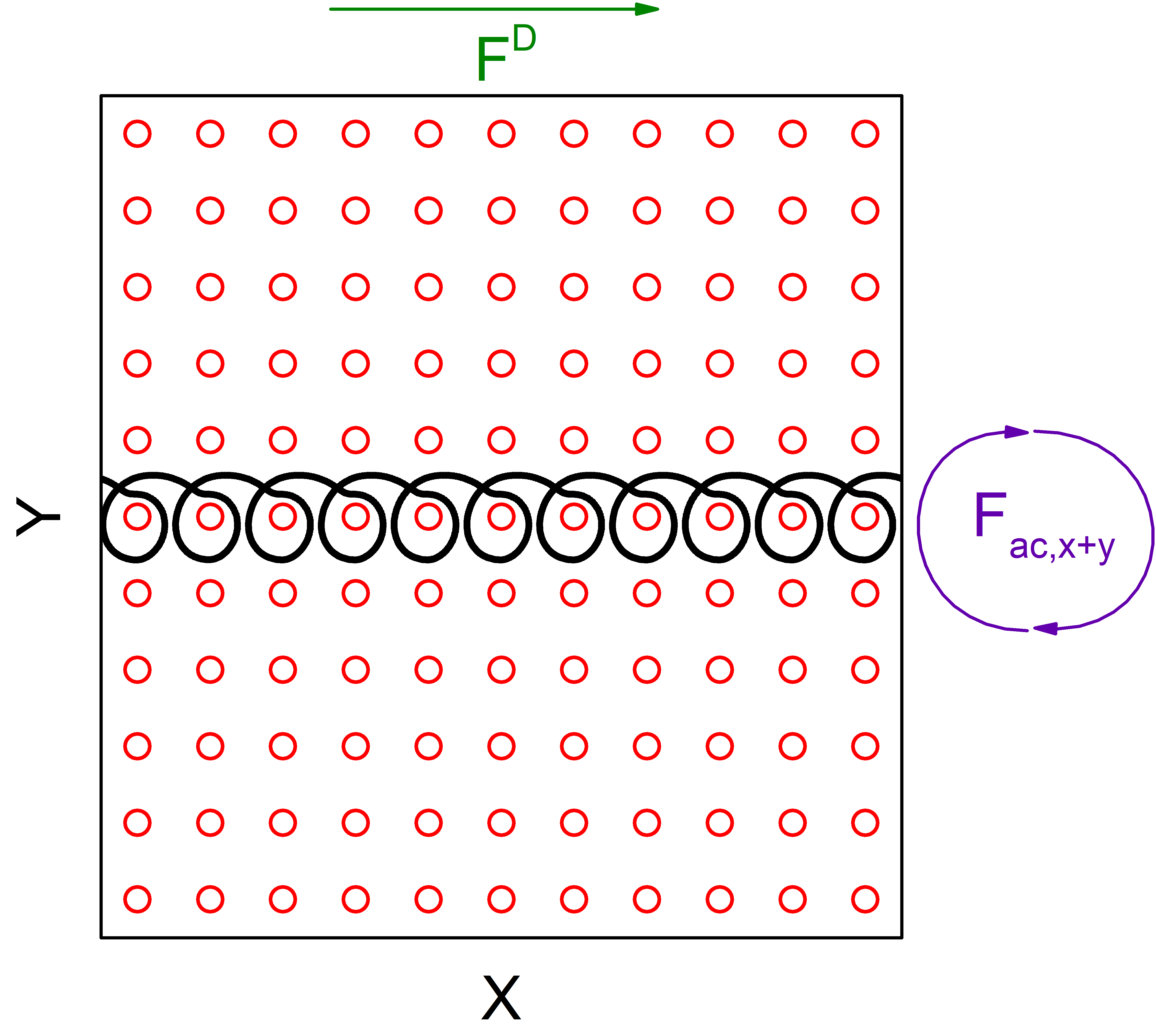
In previous work, we examined skyrmions interacting with a 2D obstacle array under only dc driving, where we found a series of directional locking effects that depend upon the size of the obstacles or whether the pinning sites are attractive or repulsive Vizarim20 . Here we consider the same system but add a biharmonic ac drive given by such that the skyrmion executes a circular orbit as illustrated in Fig. 1. For varied parameters, we find that this system exhibits a rich variety of phase locking phenomena, including phases where the skyrmion motion remains locked in a particular direction while the skyrmion orbit encircles an integer number of obstacles during each ac drive cycle. Additionally, the skyrmion Hall angle exhibits a series of increasing and/or decreasing steps as a function of increasing dc drive. We observe several phases in which the skyrmion moves at to the dc drive in spite of the fact that the intrinsic skyrmion Hall angle is much smaller than , giving an example of transverse mobility, and in some cases we find a reversal of the sign of the skyrmion Hall angle from positive to negative.
2 Simulation
We model a two-dimensional system of size with periodic boundary conditions in the and directions containing a square array of obstacles with lattice constant . We place a single skyrmion in the system and apply both a dc drive and a biharmonic ac drive which creates a circular motion of the skyrmion, as illustrated in Fig. 1. The equation of motion of the skyrmion is based upon a particle model for skyrmions used previously to model skyrmions interacting with pinning Vizarim20 ; Lin13 ; Brown19 , with the form
| (1) |
Here is the damping term which aligns the velocities of the skyrmions with the net applied forces, while is the Magnus term which produces skyrmion velocities that are perpendicular to the net forces experienced by the skyrmion. The term on the right represents the interaction force between skyrmions and obstacles, , where . The obstacle potential energy is , the potential strength is , the distance between skyrmion and obstacle is , and the obstacle radius is . We cut off the skyrmion obstacle interaction at , since beyond this length the interaction is negligible. The obstacle density is fixed at and the obstacle radius is fixed at . The term represents the dc driving force applied along the direction, as indicated in Fig. 1. We increase the dc drive in small steps of , and wait simulation time steps between drive increments to ensure that the system has reached a steady state before obtaining average velocities. We normalize the damping and Magnus coefficients to .
The ac drive has the form
| (2) |
Here, and are the ac drive amplitudes and are the ac drive frequencies. In the first part of the work we fix and , and throughout the work we fix in inverse simulation steps. We measure the skyrmion velocity parallel, , and perpendicular, , to the dc drive. In the absence of obstacles, strictly dc driving combined with the Magnus force causes the skyrmion to move at an intrinsic Hall angle of . When pinning or obstacles are present, the skyrmion Hall angle develops a drive dependence that can be measured using the ratio of the velocity transverse to the drive to the velocity parallel to the drive, .
3 dc and Biharmonic ac Drives
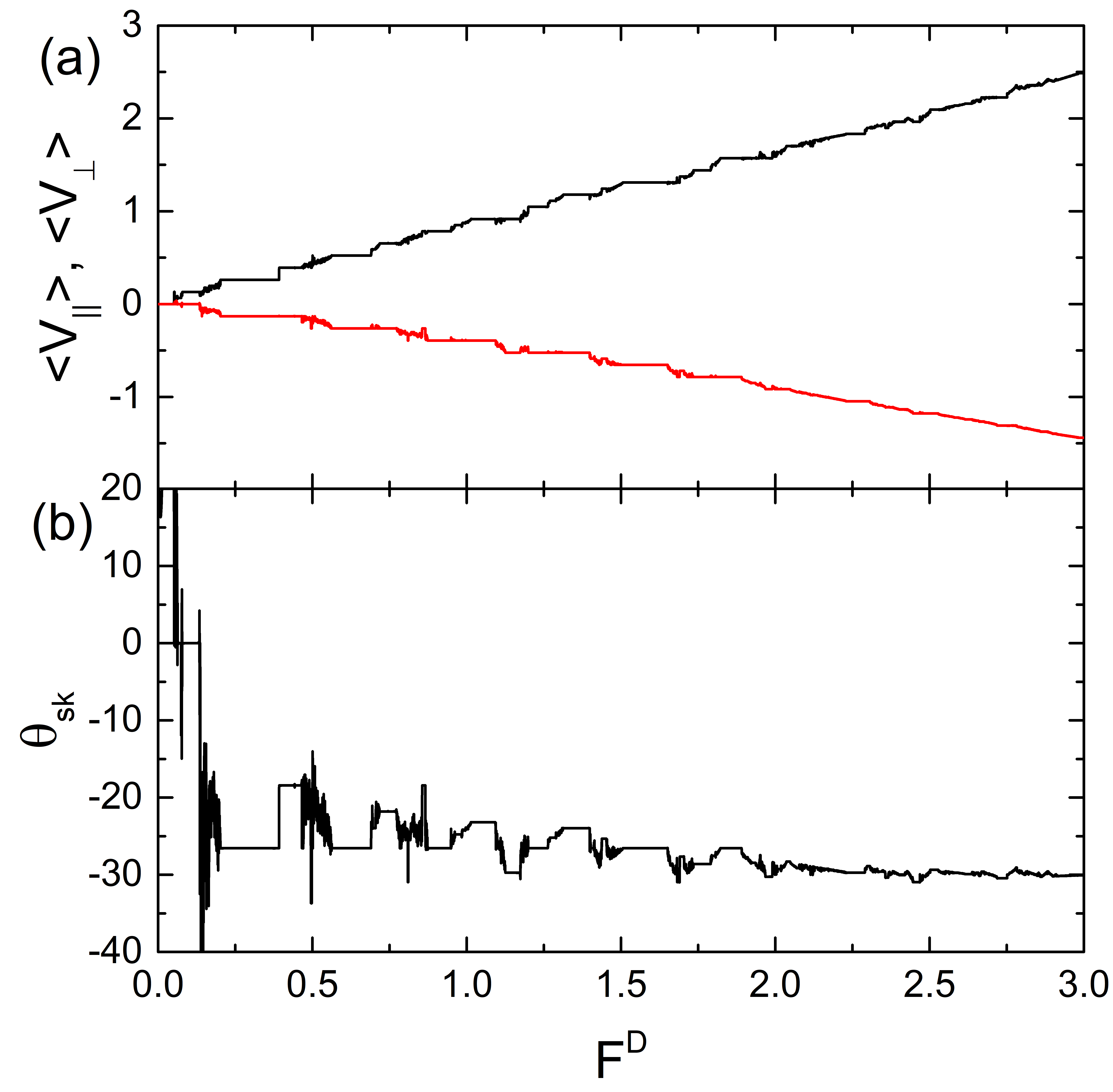
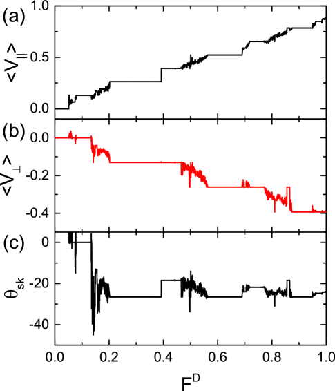
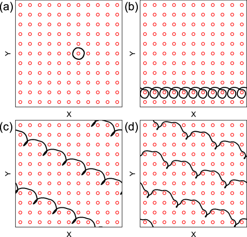
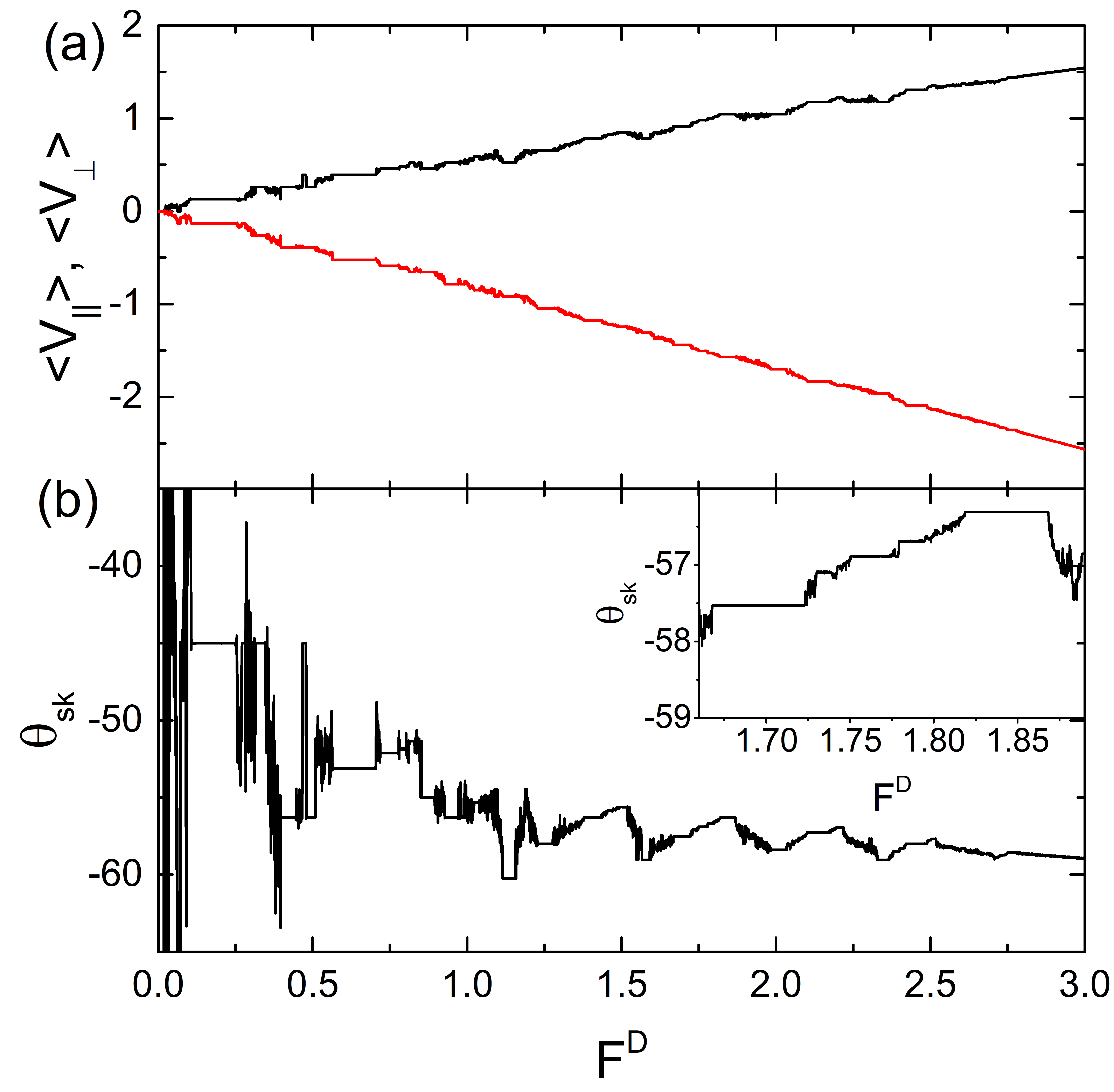
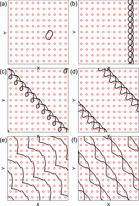
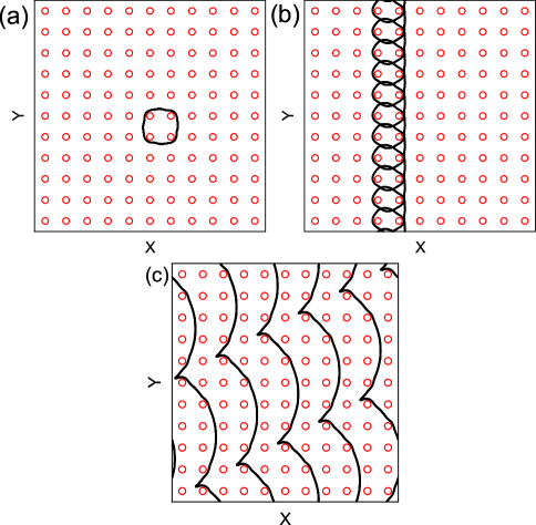
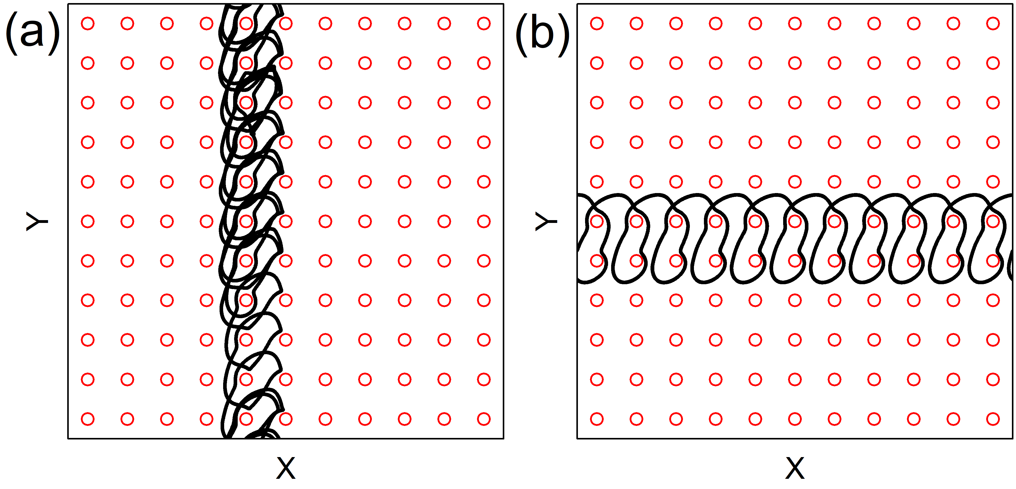
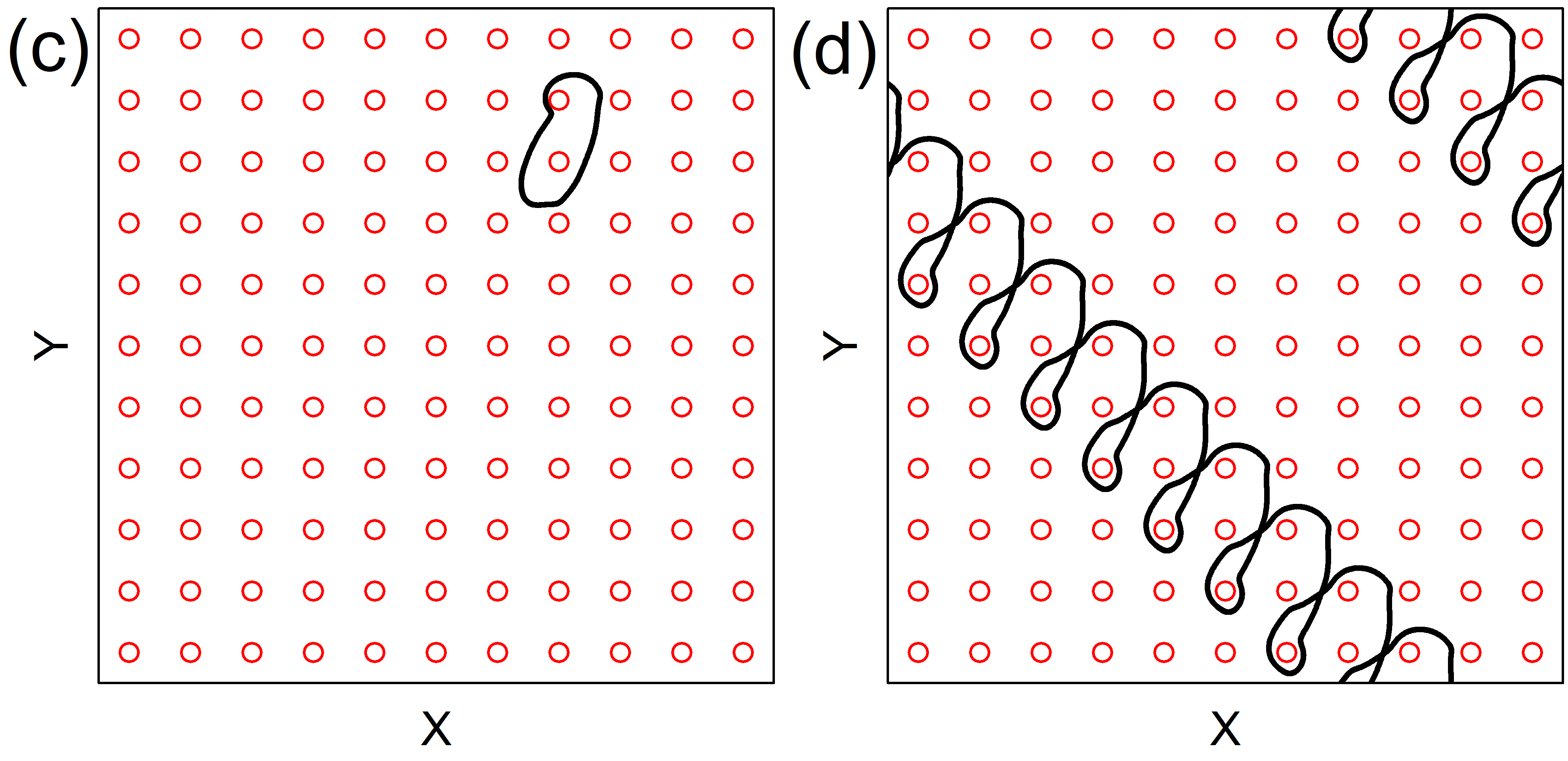
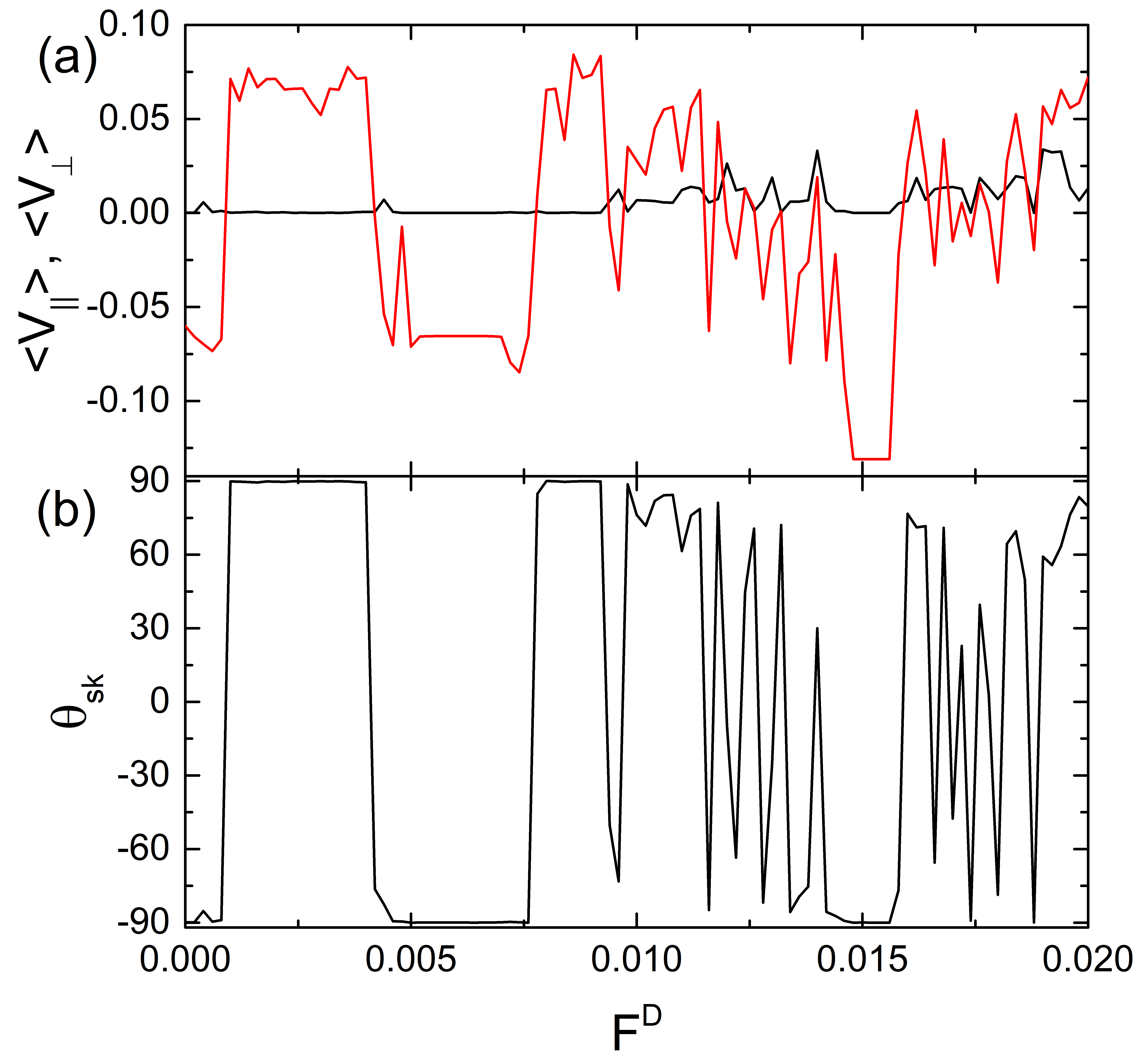
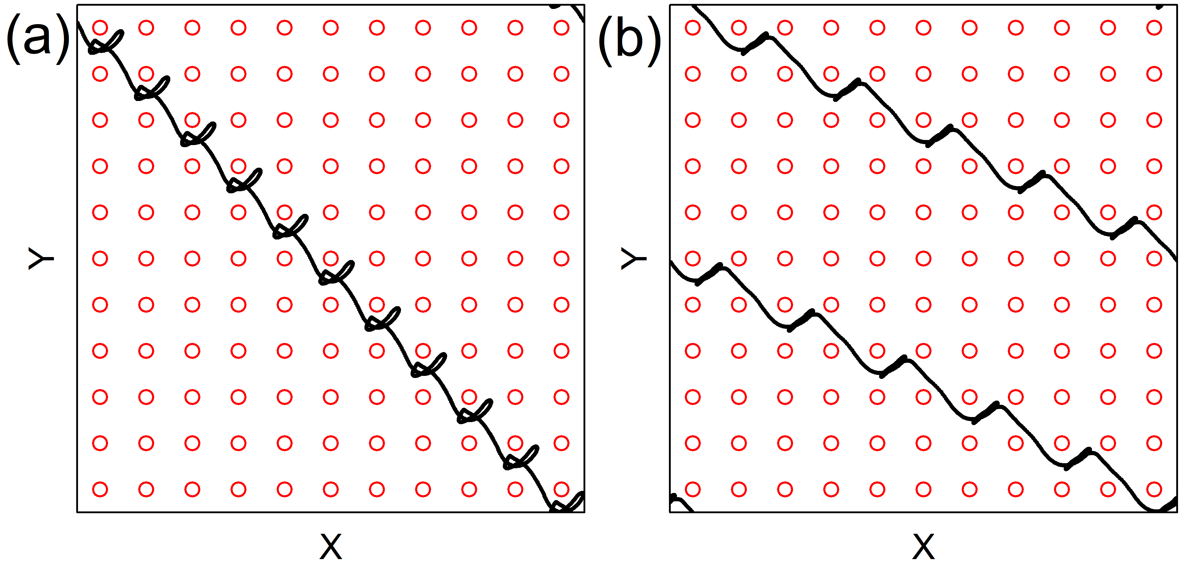
In Fig. 2(a) we plot and versus for a system with and , while in Fig. 2(b) we show the corresponding versus . Both and increase in a series of steps. There is also a series of steps in , but these steps show oscillatory jumps both up and down, indicating that the skyrmion Hall angle can both increase and decrease as a function of increasing . This is in contrast to the behavior in the absence of an ac drive where the skyrmion Hall angle monotonically increases with increasing . The intrinsic Hall angle is , and the measured gradually approaches this intrinsic value at high . In Fig. 3(a,b,c) we show a close up of , , and versus over the range for the system in Fig. 2. There is an initial pinned phase for where . In Fig. 4(a) we illustrate the skyrmion trajectory in the pinned phase at , where the skyrmion moves in a circular orbit around a single obstacle. When , the ac driving is absent and there is no pinned phase since the range of the obstacles is finite and the skyrmion can always move between the obstacles. Under a finite circular ac drive, the effective dynamical radius of the skyrmion increases, causing the skyrmion to interact with a larger number of obstacles during each ac drive cycle and permitting it to become trapped even under a finite dc drive.
In Fig. 3, is finite and over the range , giving a skyrmion Hall angle of . In Fig. 4(b) we plot the skyrmion trajectory at , where the skyrmion translates along the -direction by one obstacle per ac cycle. Within the range of drives for which the velocity is locked in the -direction, it is possible to have steps in on which the orbits are similar to those shown in Fig. 4(b) but where the skyrmion encircles each obstacle twice in a single ac cycle before translating by one lattice constant in the direction. For , the skyrmion begins to move in the direction as well and the dynamics is more chaotic, with no drive interval over which the motion is locked to a specific direction. For , the skyrmion motion is periodic and locked to an angle of . Here, during each ac drive cycle, the skyrmion translates by two lattice constants in the direction and one in the direction, giving . In Fig. 4(c) we illustrate a skyrmion trajectory in this regime at . When , the magnitude of the skyrmion Hall angle decreases and the locking angle is , with the skyrmion moving in the direction and in the direction during each ac drive cycle, as shown in Fig. 4(d) at . As increases further, jumps between the two main locking directions of and , and additional fractional locking steps appear in the velocities and the skyrmion Hall angle corresponding to and . There are also several regions of chaotic motion.
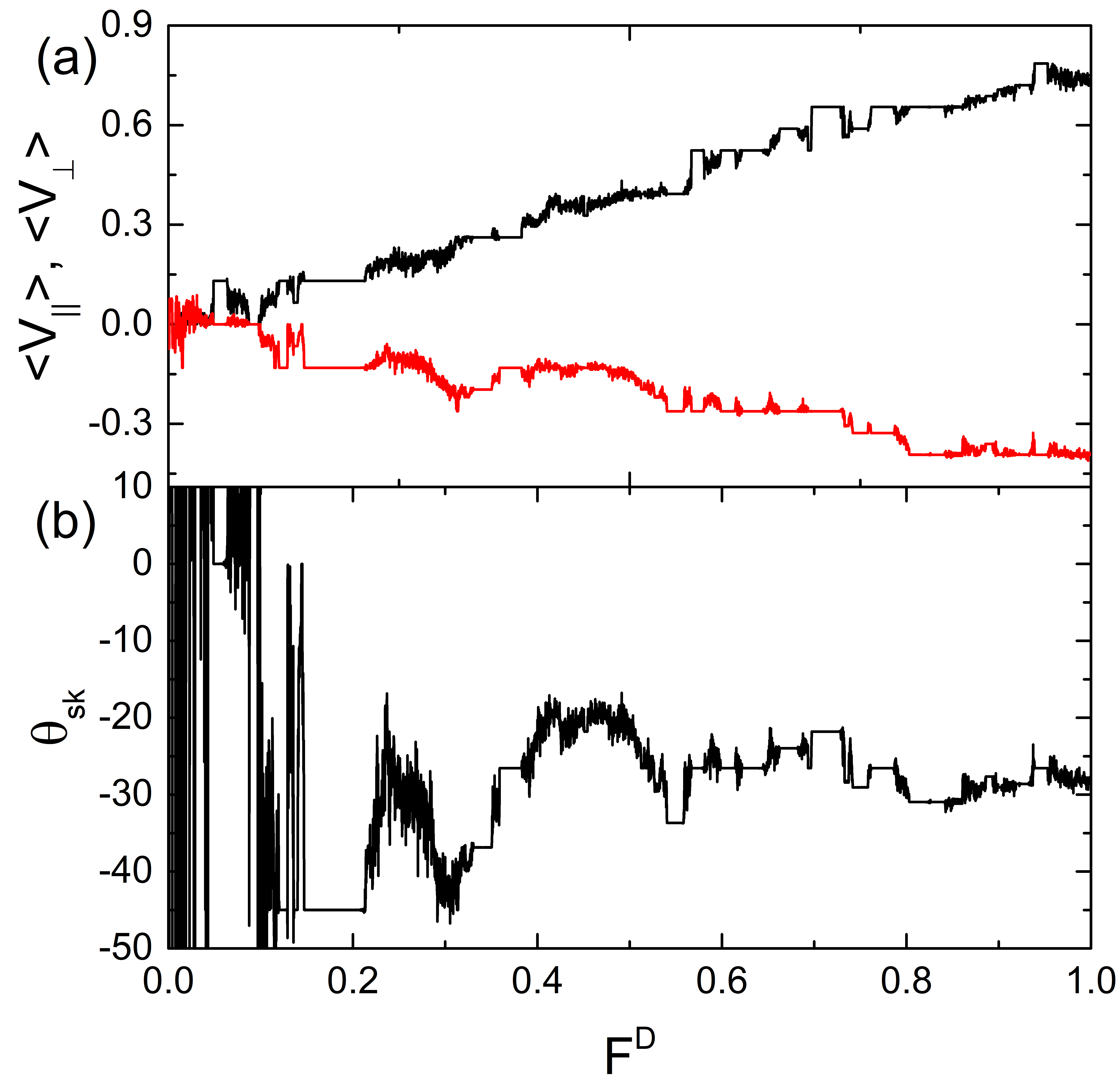
In Fig. 5(a) we plot and versus for a system with and , while in Fig. 5(b) we show the corresponding versus curve. Here, . The number of locking steps is higher than for samples with lower intrinsic skyrmion Hall angles, and we observe a series of jumps in . The jumps primarily appear for , while has a more oscillating behavior for . The inset of Fig. 5(b) shows over the range , highlighting the large number of locking steps that accompany a decrease in the magnitude of . As is increased further, gradually approaches the intrinsic value . In Fig. 6(a) we plot the skyrmion trajectory for the system in Fig. 5 at , where a pinned orbit occurs in which the skyrmion encircles two obstacles during each ac drive cycle. In Fig. 6(b) at , and is finite, giving . This is an example of absolute transverse mobility in which the skyrmion translation is strictly perpendicular to the applied dc drive. The interval of over which transverse mobility occurs is small, but it can be extended by varying other parameters as we demonstrate later. At in Fig. 6(c), the motion is locked to and the skyrmion completes a loop around an obstacle during every ac cycle. In Fig. 6(d) at , the trajectory is still locked to but the shape of the orbit has changed. At in Fig. 6(e), and the skyrmion translates a distance of in the direction and in the direction during each ac drive cycle. In Fig. 6(f), the trajectories at are one example of the many possible phase locking orbits that the system exhibits.
In general, the locking steps arise due to a combination of effects. The first is the directional locking associated with the drive dependence of the skyrmion Hall angle that occurs in the presence of pinning and in the absence of ac driving Reichhardt15a . Steps in occur at prominent locking angles that match the symmetry directions of the underlying obstacle lattice. The second effect is the Shapiro or phase locking steps that appear due to the locking of the ac drive frequency with the periodicity of the velocity component induced by the motion of the skyrmion over the periodic substrate Reichhardt15b . Since the skyrmion is moving in both the and directions, there are two different velocity frequencies that can resonate with the ac drive frequency in order to create the Shapiro steps, providing additional possible ways in which phase locking can occur. The combined effect of the directional locking and the Shapiro steps accounts for the large number of phase locking steps that appear in the velocity-force curves under combined dc and ac driving. Many of these different phase locking effects compete with one another, producing frustration effects where, under certain driving conditions, the skyrmion can lock to multiple phase locked orbits for the same , causing the skyrmion to jump between the different orbits and producing the chaotic regimes in the velocity-force curves.
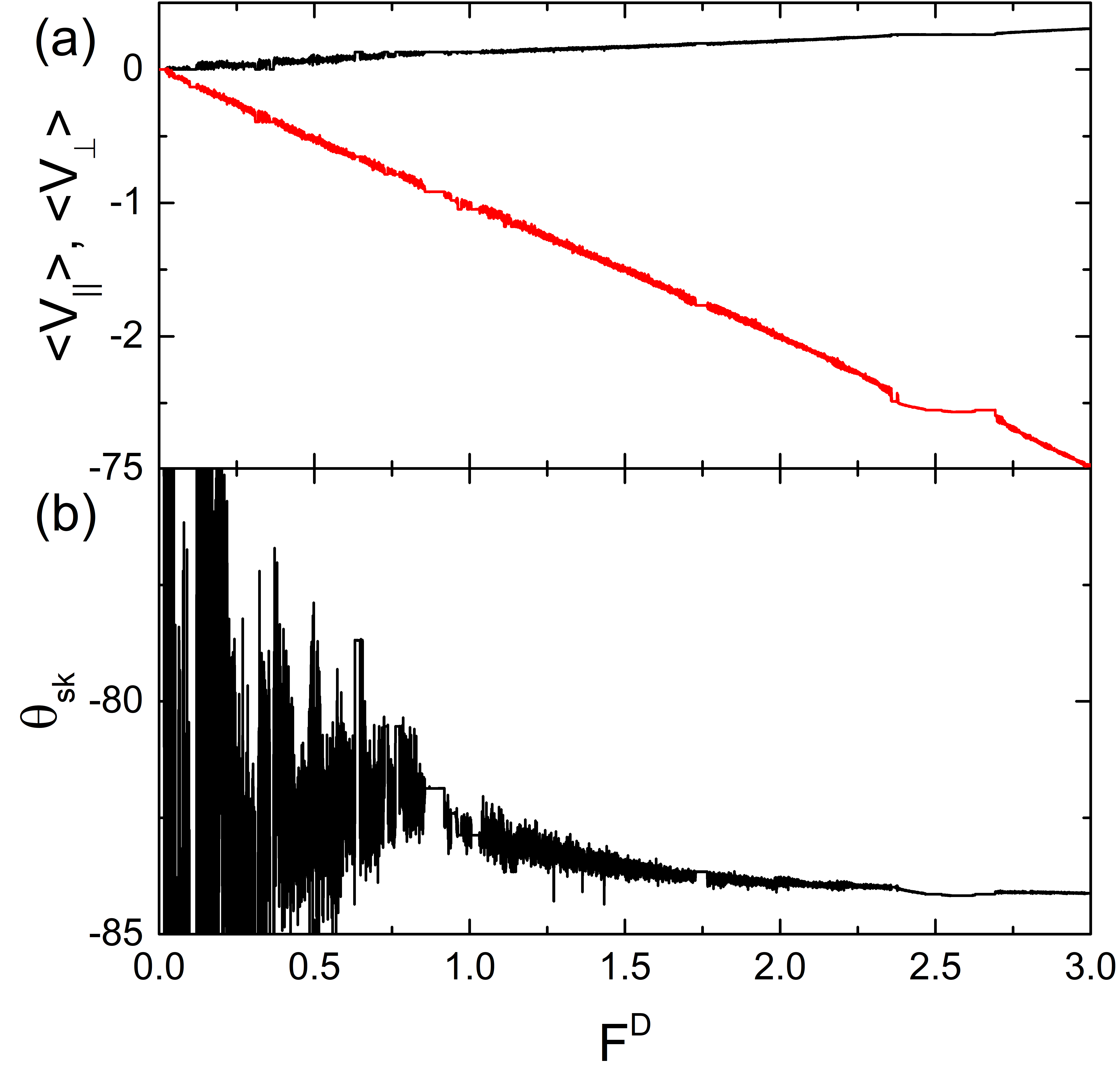
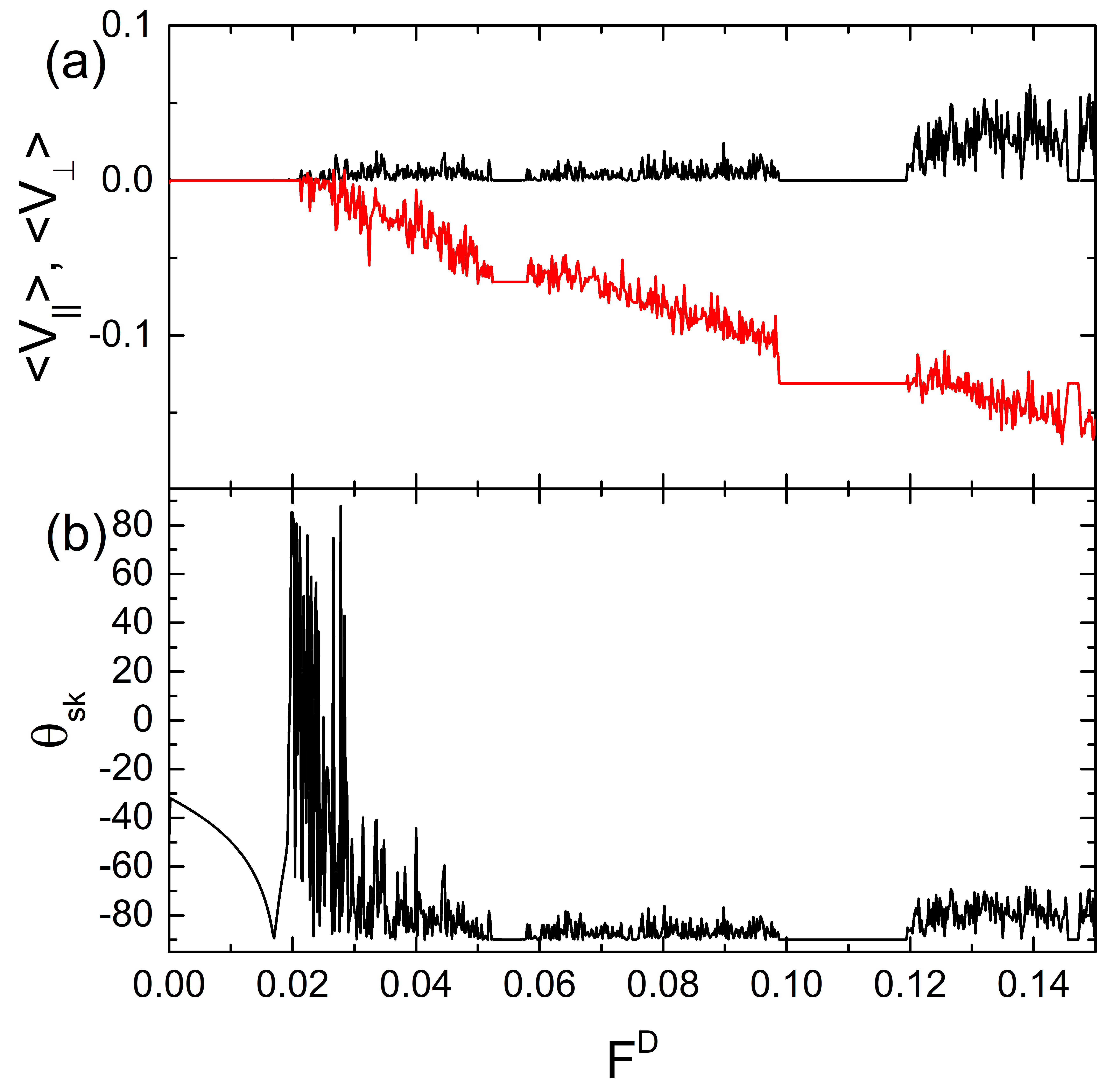
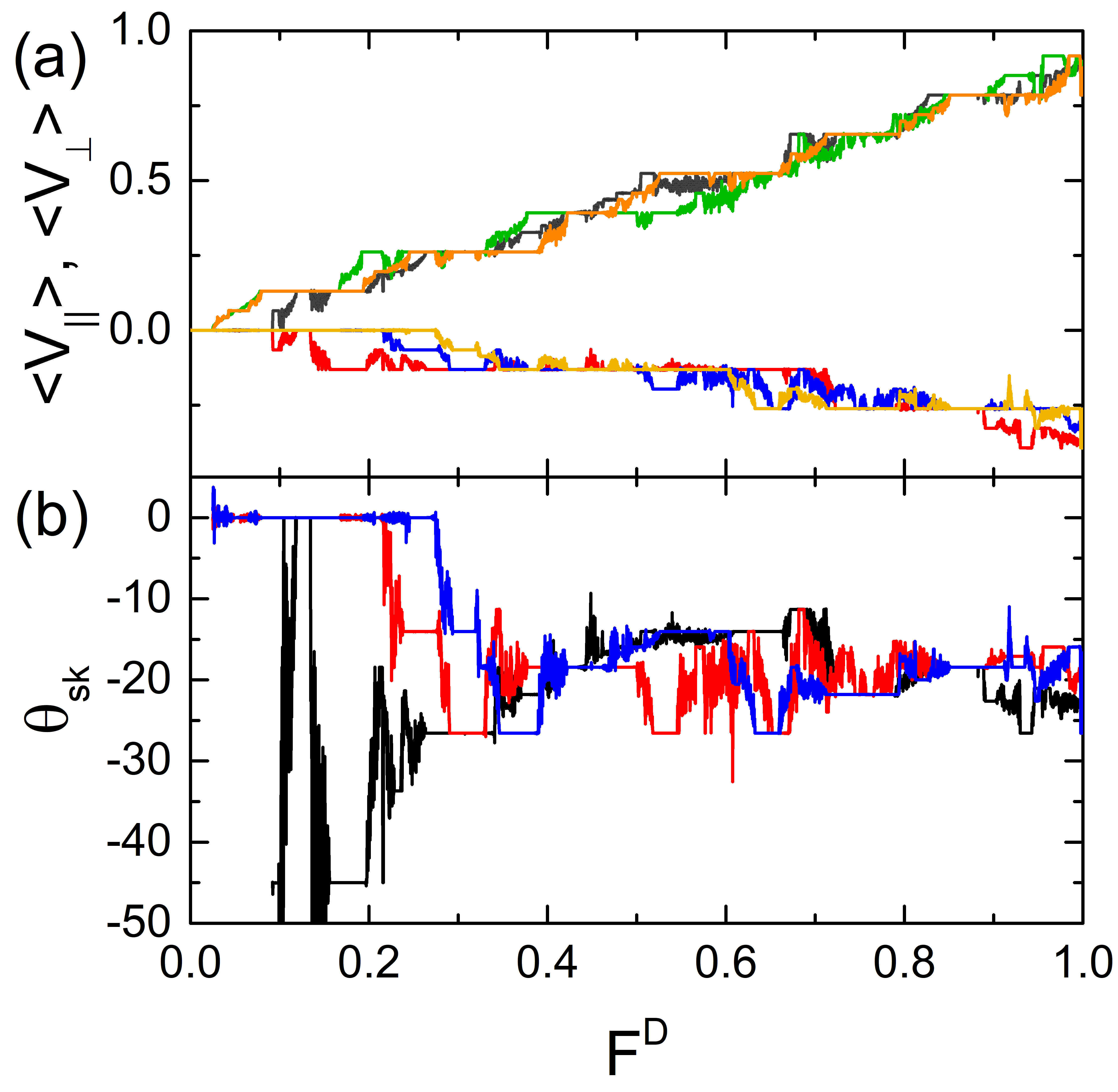
In Fig. 7(a) we plot and versus and in Fig. 7(b) we show the corresponding versus for a system with and , where . The windows of disordered motion are now larger, but there are still some steps in the velocity-force curves corresponding to different locking phases. In Fig. 8 we show a blow up of the velocity-force curves from Fig. 7 over the range . At low , there is a pinned region with . For higher , we find a regime in which while the magnitude of is increasing with increasing , which is an example of transverse mobility. In Fig. 8(b), the corresponding versus shows that there is an interval over which the Hall angle is close to . In Fig. 9(a) we show the skyrmion trajectory for the system in Fig. 8 at in the pinned phase, where the skyrmion encircles four obstacles in a single ac drive cycle. The radius of the pinned orbit increases with increasing Magnus force because the Magnus term effectively magnifies the ac driving amplitude. At in Fig. 9(b), we illustrate the transverse mobility regime where the skyrmion moves in the negative direction and encircles two obstacles during every ac drive cycle. In Fig. 9(c) at , the motion is locked to and the skyrmion translates a distance in the direction and in the direction during every ac drive cycle, giving .
4 Varied ac Drive Amplitude
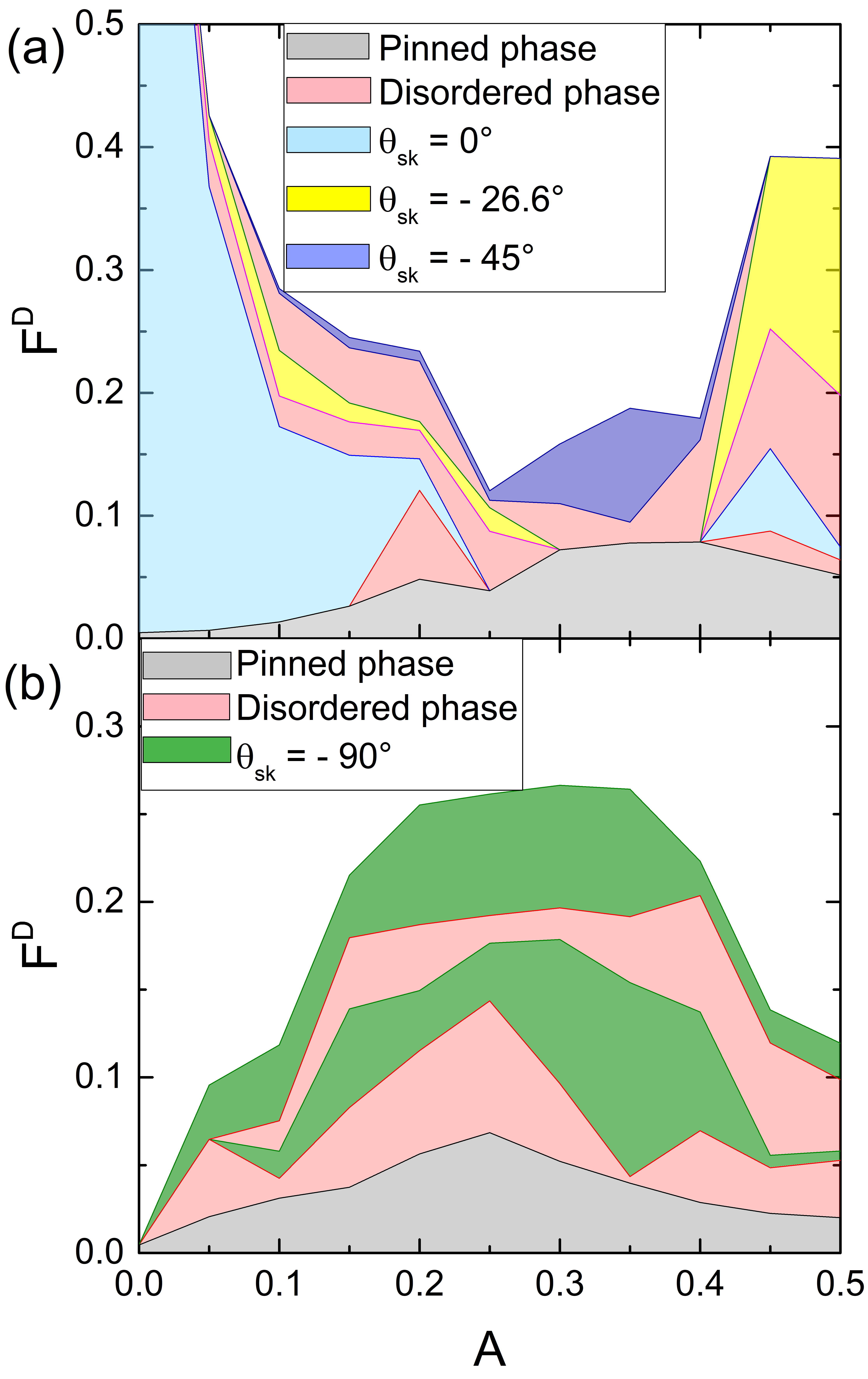
We next consider the effect on the velocity-force curves of varying the ac drive amplitude over the range to for a fixed driving frequency. Due to the very large number of different locking effects that arise, we summarize the results for only a few selected locking phases and disordered phases. In Fig. 10(a) we plot a dynamic phase diagram as a function of dc drive versus ac drive amplitude for the system in Fig. 2 with and . We highlight only the pinned phase, disordered phase, locking, locking, and locking. When , the system is in the pinned phase for and the phase for . As increases above , the system jumps to different locking phases (not shown). When increases, the width of the pinned phase grows until it reaches a maximum near . The locking phase is absent for , which coincides with the window in which the locking phase reaches its largest extent. Disordered regions appear between the different locking phases. For , the skyrmion orbit is small enough that the skyrmion is not able to encircle any obstacles, while for , the orbit begins to encircle a single obstacle. For (not shown), we find a series of pinned phases in which the skyrmion encircles one, two, four, and then nine obstacles.
In Fig. 10(b) we plot the dynamic phase diagram as a function of versus for the system in Figs. 7 and 8 with . We highlight only the pinned phase, the disordered phase, and the regime of absolute transverse mobility with . The maximum extent of the pinned phase occurs for , which also corresponds to the ac drive at which the transverse mobility reaches its largest extent. There are two distinct windows of traverse mobility that are associated with two different types of skyrmion orbits. When , the skyrmion does not encircle any obstacles, while for larger it encircles four obstacles. The reduction in the extent of the pinning and transverse mobility regions for larger is the result of the larger orbit generated by the ac driving, with the skyrmion jumping to an orbit that encircles obstacles for .
These results indicate that the transverse mobility is most prominent for higher values of where the intrinsic Hall angle is the largest.
4.1 Two Different ac Amplitudes and Skyrmion Hall Angle Reversal
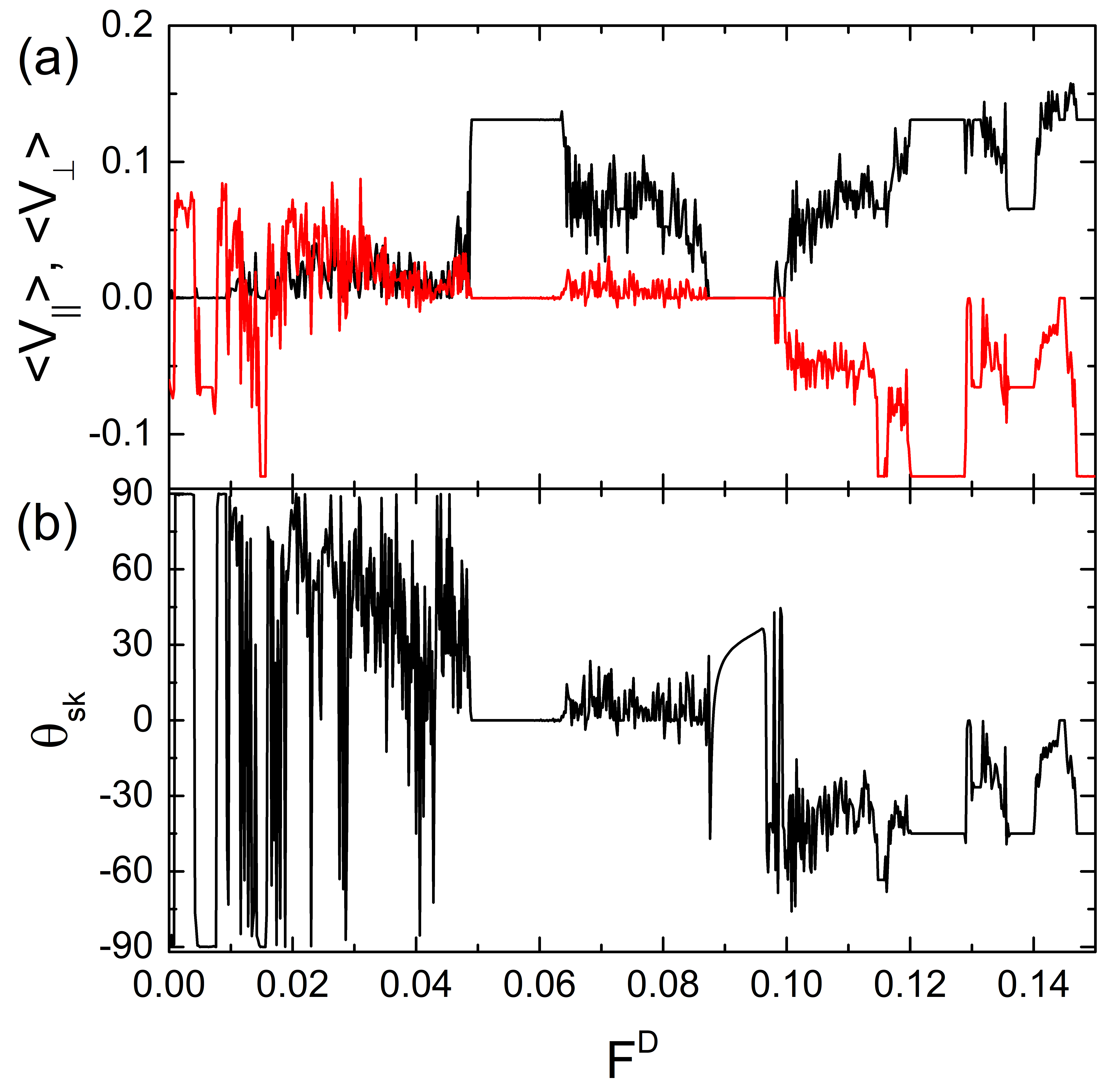
We next consider the case where the ac drive amplitudes are different in the two directions, . In Fig. 11 we plot , , and versus for a system with , , and . Here there is an extended region over which the system locks to followed by a gradual decline to for higher drives while a variety of locking steps and disordered regions appear. In Fig. 12(a) we show and versus for the same system as in Fig. 11 but zoomed in over the range . At low , there is an extended region over which the motion is locked to the -direction. The system has a reentrant pinned region near where . Figure 12(b) shows the corresponding versus curve. For , the skyrmion Hall angle is oscillatory and undergoes repeated reversals from positive to negative values. The finite value of in the pinned region near results from the undefined calculation that occurs when both the parallel and perpendicular velocities are zero. In Fig. 13(a) we illustrate the skyrmion trajectories for the system in Fig. 12 at where transverse mobility occurs. The skyrmion is moving in the positive direction, giving a positive skyrmion Hall angle. In Fig. 13(b) at , the motion is locked in the -direction and the skyrmion encircles two obstacles during every ac drive cycle. Figure 13(c) shows the pinned orbit at , where the skyrmion encircles two obstacles but does not translate. In Fig. 13(d) at , the motion is locked to .
In Fig. 14(a) we show a zoom of and versus for the system in Fig. 12 over the range , and in Fig. 14(b) we show the corresponding . The system passes though a series of locked phases that are associated with transverse mobility, but there are also repeated reversals of the Hall angle with increasing . After each reversal, the system locks to a different orbit. Another interesting feature is that at , the skyrmion has a finite velocity in the negative -direction. This motion, which occurs under only the ac drive without a dc drive, represents a type of ratchet effect. In overdamped systems, similar ratchet effects can occur for a particle on a periodic substrate that is subjected to biharmonic ac drives Reichhardt03 ; Speer09 . The ratchet effect occurs when enough symmetries are broken in a nonequilibrium system. The circular ac drive breaks a chiral symmetry, but in the absence of a substrate asymmetry, the ac orbit must itself be spatially asymmetric in order to produce the ratchet effect. A simple circular ac drive with does not give rise to a ratchet effect. In the skyrmion system, the Magnus force combined with the dc driving can produce asymmetric orbits, as illustrated for the pinned phase in Fig. 13(c). The ratchet effects that occur at will be explored more fully in a future work. In general, the ratchet effects are more relevant at lower , whereas for high dc drives the Shapiro step and directional locking effects dominate the behavior.
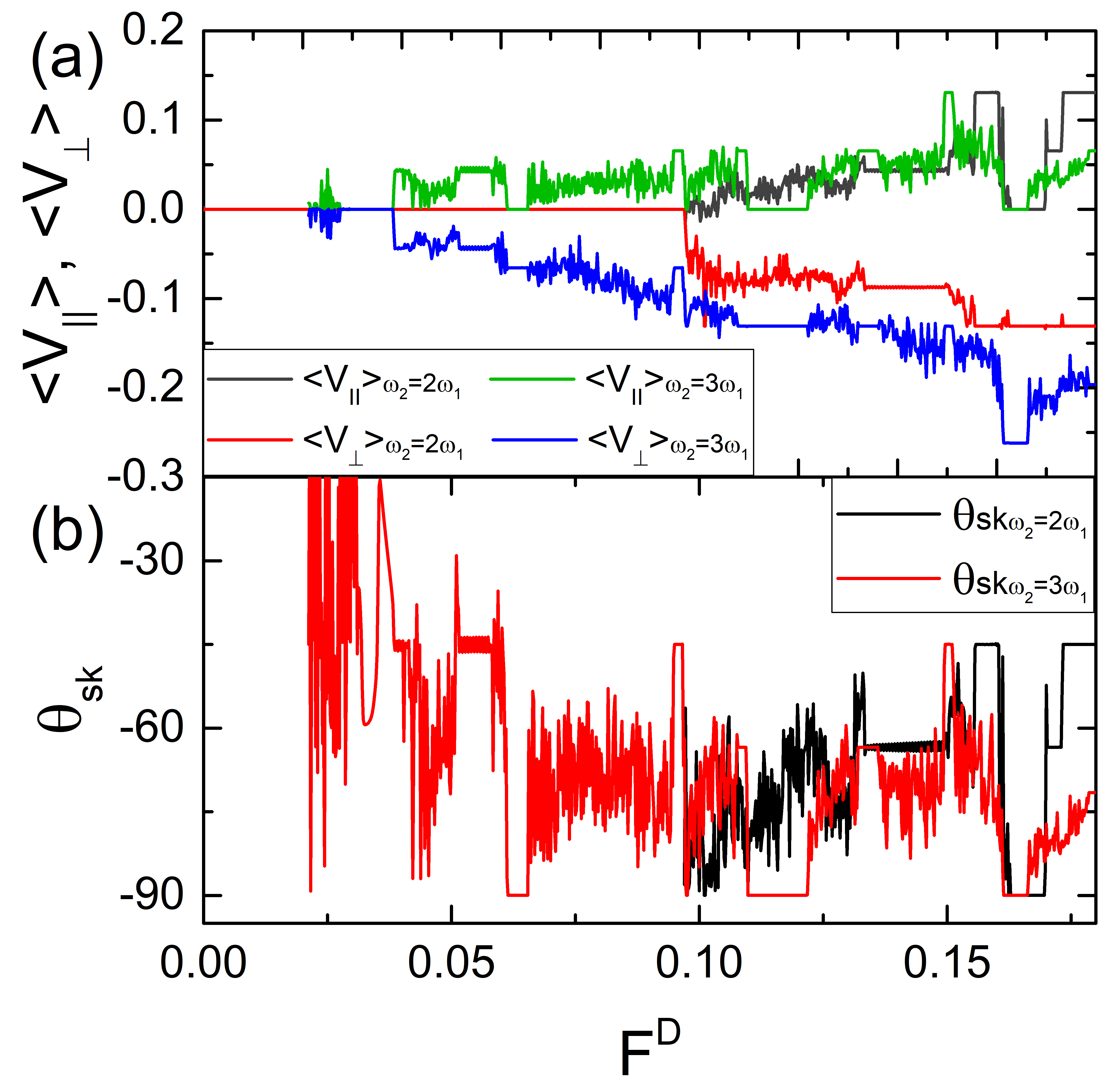
We next consider the effect of holding the ac drive amplitudes fixed at but varying the ac drive frequencies so that . In Fig. 15(a), we plot and for systems with , and at , , and , while in Fig. 15(b) we show the corresponding versus curves. We observe several trends. Certain locking phases occur for all three values of ; however, the width of the locked phases varies as varies. When , the system locks to at lower drives and then gradually approaches the intrinsic Hall angle. In Fig. 16(a) we illustrate the skyrmion trajectory for the sample at , where the skyrmion is locked to and performs a double loop during each ac drive cycle. Figure 16(b) shows the trajectory at , where the skyrmion is moving at .
In Fig. 17(a) we plot and versus for a system with and . When , there is an initial pinned phase at low . The system locks to over several drive intervals, and there are also several regions in which absolute transverse mobility occurs with as shown in the plot of versus in Fig. 17(b). When , the pinned region extends out to larger drives, and there are also several drive intervals at which . These results show that the transverse mobility can be enhanced by varying the ac drive frequencies.
5 Discussion
In this work, we neglected temperature; however, thermal effects can be important in certain skyrmion systems. Thermal fluctuations can wash out directional phase locking, but in some cases they can also induce other types of phase locking effects Mali20 . Experiments that could be performed in this system include direct imaging of skyrmions and measurements of changes in the topological Hall effect. Another route for further exploration would be to examine noise fluctuations Diaz17 in order to observe the emergence of narrow band signals associated with phase locking. It has already been shown experimentally that such measurements are possible in skyrmion systems Sato19 . In the locked phases, the skyrmion motion should be periodic and produce a large narrow band noise signal, while in the disordered regions this signal will be reduced or lost. It would also be interesting to explore the effect of the internal modes of the skyrmions Chen19 ; Chen20 , which could induce additional oscillating signals that might produce different types of phase locking. We have focused only on the case of a single skyrmion; however, if lattices of skyrmions interact with 2D periodic arrays, we expect that additional collective effects would occur that would depend on the filling factor or the number of skyrmions relative to the number of pinning sites. Slightly away from commensurate fillings, at which the number of skyrmions is an integer multiple of the number of pinning sites, soliton like states can appear which could themselves exhibit Shapiro steps and other phase locking phenomena, similar to what has been observed in colloidal and superconducting vortex systems with periodic substrate arrays. The additional Magnus force that is present in the skyrmion system could induce new types of dynamics that do not occur in overdamped systems.
6 Summary
We examined a skyrmion interacting with a 2D periodic array of obstacles under an applied dc drive and biharmonic ac drive, and find a rich variety of nonlinear dynamical effects due to the presence of the Magnus force and the velocity dependence of the skyrmion Hall angle. A biharmonic ac drive alone creates a circular skyrmion orbit in the absence of obstacles or a dc drive. Under only dc driving and in the presence of the periodic obstacles, the skyrmion passes through a series of directional locking phases due to the velocity dependence of the skyrmion Hall effect. When a finite biharmonic ac drive is included, we find that the velocity-force curves show a series of jumps and locking intervals in which the skyrmion motion locks to specific symmetry directions of the substrate. Within these locking phases, the skyrmion can encircle multiple obstacles during each ac drive cycle. We also observe regimes in which the skyrmion motion is disordered and the motion is not locked to a fixed direction. We find that the locking phases can be associated with both increases and decreases in the skyrmion Hall angle. Many of the locking phases are reentrant and recur repeatedly for increasing dc drive. In general, as the Magnus force increases, the skyrmion encircles a larger number of obstacles during each ac drive cycle, and for large Magnus forces, we observe a series of absolute transverse mobility phases in which the skyrmion moves at exactly with respect to the dc driving direction. We find reentrance in both the transverse mobility and the pinning phase. We show that it is possible to have oscillations in the transverse mobility where the skyrmion Hall angle switches between and . We also find that the transverse mobility can be enhanced when the two ac drives have different amplitudes or different frequencies so that the driving is no longer circular.
This work was supported by the US Department of Energy through the Los Alamos National Laboratory. Los Alamos National Laboratory is operated by Triad National Security, LLC, for the National Nuclear Security Administration of the U. S. Department of Energy (Contract No. 892333218NCA000001). N.P.V. acknowledges funding from Fundação de Amparo à Pesquisa do Estado de São Paulo - FAPESP (Grant 2018/13198-7).
7 Authors contributions
All the authors were involved in the preparation of the manuscript. All the authors have read and approved the final manuscript.
References
- (1) K. Harada, O. Kamimura, H. Kasai, T. Matsuda, A. Tonomura, V.V. Moshchalkov, Science 274, 1167 (1996)
- (2) C. Reichhardt, C.J. Olson, F. Nori, Phys. Rev. Lett. 78, 2648 (1997)
- (3) J.I. Martín, M. Vélez, A. Hoffmann, I.K. Schuller, J.L. Vicent, Phys. Rev. Lett. 83, 1022 (1999)
- (4) C. Reichhardt, C.J.O. Reichhardt, Phys. Rev. B 78, 224511 (2008)
- (5) J. Gutierrez, A.V. Silhanek, J. Van de Vondel, W. Gillijns, V.V. Moshchalkov, Phys. Rev. B 80, 140514 (2009)
- (6) I.A. Sadovskyy, Y.L. Wang, Z.L. Xiao, W.K. Kwok, A. Glatz, Phys. Rev. B 95, 075303 (2017)
- (7) J.Y. Ge, V.N. Gladilin, J. Tempere, J.T. Devreese, V.V. Moshchalkov, Nature Commun. 9, 2576 (2018)
- (8) P.T. Korda, M.B. Taylor, D.G. Grier, Phys. Rev. Lett. 89, 128301 (2002)
- (9) M.P. MacDonald, G.C. Spalding, K. Dholakia, Nature (London) 426, 421 (2003)
- (10) T. Bohlein, J. Mikhael, C. Bechinger, Nature Mater. 11, 126 (2012)
- (11) A. Vanossi, N. Manini, E. Tosatti, Proc. Natl. Acad. Sci. (USA) 109, 16429 (2012)
- (12) J. Hasnain, S. Jungblut, C. Dellago, Soft Matter 9, 5867 (2013)
- (13) D. McDermott, J. Amelang, C.J.O. Reichhardt, C. Reichhardt, Phys. Rev. E 88, 062301 (2013)
- (14) P. Tierno, F. Sagues, T.H. Johansen, T.M. Fischer, Phys. Chem. Chem. Phys. 11, 9615 (2009)
- (15) J. Loehr, D. de las Heras, A. Jarosz, M. Urbaniak, F. Stobiecki, A. Tomita, R. Huhnstock, I. Koch, A. Ehresmann, D. Holzinger et al., Commun. Phys. 1, 4 (2018)
- (16) X. Cao, E. Panizon, A. Vanossi, N. Manini, C. Bechinger, Nature Phys. 15, 776 (2019)
- (17) R.L. Stoop, A.V. Straube, T.H. Johansen, P. Tierno, Phys. Rev. Lett. 124, 058002 (2020)
- (18) J. Tekić, O.M. Braun, B. Hu, Phys. Rev. E 71, 026104 (2005)
- (19) A. Vanossi, N. Manini, M. Urbakh, S. Zapperi, E. Tosatti, Rev. Mod. Phys. 85, 529 (2013)
- (20) S. Shapiro, Phys. Rev. Lett. 11, 80 (1963)
- (21) A. Barone, G. Paterno, Physics and Applications of the Josephson effect (Wiley, New York, 1982)
- (22) P. Martinoli, O. Daldini, C. Leemann, E. Stocker, Sol. St. Commun. 17, 205 (1975)
- (23) L. Van Look, E. Rosseel, M.J. Van Bael, K. Temst, V.V. Moshchalkov, Y. Bruynseraede, Phys. Rev. B 60, R6998 (1999)
- (24) C. Reichhardt, R.T. Scalettar, G.T. Zimányi, N. Grønbech-Jensen, Phys. Rev. B 61, R11914 (2000)
- (25) O.V. Dobrovolskiy, J. Supercond. Novel Mag. 28, 469 (2015)
- (26) M.P.N. Juniper, A.V. Straube, R. Besseling, D.G.A.L. Aarts, R.P.A. Dullens, Nature Commun. 6, 7187 (2015)
- (27) T. Brazda, C. July, C. Bechinger, Soft Matter 13, 4024 (2017)
- (28) C. Reichhardt, A.B. Kolton, D. Domínguez, N. Grønbech-Jensen, Phys. Rev. B 64, 134508 (2001)
- (29) V.I. Marconi, A.B. Kolton, D. Domínguez, N. Grønbech-Jensen, Phys. Rev. B 68, 104521 (2003)
- (30) C. Reichhardt, C.J. Olson, Phys. Rev. B 65, 100501 (2002)
- (31) R. Guantes, S. Miret-Artés, Phys. Rev. E 67, 046212 (2003)
- (32) C. Reichhardt, C.J. Olson Reichhardt, Phys. Rev. E 68, 046102 (2003)
- (33) D. Speer, R. Eichhorn, P. Reimann, Phys. Rev. Lett. 102, 124101 (2009)
- (34) R. Chacón, A.M. Lacasta, Phys. Rev. E 82, 046207 (2010)
- (35) A.K. Mukhopadhyay, B. Liebchen, P. Schmelcher, Phys. Rev. Lett. 120, 218002 (2018)
- (36) C. Reichhardt, C.J. Olson, Phys. Rev. B 65, 174523 (2002)
- (37) P. Tierno, T.H. Johansen, T.M. Fischer, Phys. Rev. Lett. 99, 038303 (2007)
- (38) A. Soba, P. Tierno, T.M. Fischer, F. Saguès, Phys. Rev. E 77, 060401 (2008)
- (39) P. Ao, D.J. Thouless, Phys. Rev. Lett. 70, 2158 (1993)
- (40) H. Yabu, H. Kuratsuji, Found. Phys. 27, 1585 (1997)
- (41) A.J. Groszek, D.M. Paganin, K. Helmerson, T.P. Simula, Phys. Rev. A 97, 023617 (2018)
- (42) V.S. Pribiag, I.N. Krivorotov, G.D. Fuchs, P.M. Braganca, O. Ozatay, J.C. Sankey, D.C. Ralph, R.A. Buhrman, Nature Phys. 3, 498 (2007)
- (43) M. Bolte, G. Meier, B. Krüger, A. Drews, R. Eiselt, L. Bocklage, S. Bohlens, T. Tyliszczak, A. Vansteenkiste, B. Van Waeyenberge et al., Phys. Rev. Lett. 100, 176601 (2008)
- (44) J. Wiersig, K.H. Ahn, Phys. Rev. Lett. 87, 026803 (2001)
- (45) M. Khoury, A.M. Lacasta, J.M. Sancho, A.H. Romero, K. Lindenberg, Phys. Rev. B 78, 155433 (2008)
- (46) B.C. van Zuiden, J. Paulose, W.T.M. Irvine, D. Bartolo, V. Vitelli, Proc. Natl. Acad. Sci. (USA) 113, 12919 (2016)
- (47) M. Han, J. Yan, S. Granick, E. Luijten, Proc. Natl. Acad. Sci. (USA) 114, 7513 (2017)
- (48) C. Reichhardt, C.J.O. Reichhardt, Phys. Rev. E 100, 012604 (2019)
- (49) S. Yazdi, J.L. Aragones, J. Coulter, A. Alexander-Katz (2020), arXiv:2002.06477
- (50) S. Mühlbauer, B. Binz, F. Jonietz, C. Pfleiderer, A. Rosch, A. Neubauer, R. Georgii, P. Böni, Science 323, 915 (2009)
- (51) X.Z. Yu, Y. Onose, N. Kanazawa, J.H. Park, J.H. Han, Y. Matsui, N. Nagaosa, Y. Tokura, Nature (London) 465, 901 (2010)
- (52) N. Nagaosa, Y. Tokura, Nature Nanotechnol. 8, 899 (2013)
- (53) T. Schulz, R. Ritz, A. Bauer, M. Halder, M. Wagner, C. Franz, C. Pfleiderer, K. Everschor, M. Garst, A. Rosch, Nature Phys. 8, 301 (2012)
- (54) J. Iwasaki, M. Mochizuki, N. Nagaosa, Nature Commun. 4, 1463 (2013)
- (55) S. Woo, K. Litzius, B. Krüger, M.Y. Im, L. Caretta, K. Richter, M. Mann, A. Krone, R.M. Reeve, M. Weigand et al., Nature Mater. 15, 501 (2016)
- (56) J. Tekić, A.E. Botha, P. Mali, Y.M. Shukrinov, Phys. Rev. E 99, 022206 (2019)
- (57) L. Xiong, B. Zheng, M.H. Jin, N.J. Zhou, Phys. Rev. B 100, 064426 (2019)
- (58) C. Reichhardt, D. Ray, C.J.O. Reichhardt, Phys. Rev. B 91, 104426 (2015)
- (59) C. Reichhardt, D. Ray, C.J.O. Reichhardt, Phys. Rev. Lett. 114, 217202 (2015)
- (60) W. Jiang, X. Zhang, G. Yu, W. Zhang, X. Wang, M.B. Jungfleisch, J.E. Pearson, X. Cheng, O. Heinonen, K.L. Wang et al., Nature Phys. 13, 162 (2017)
- (61) K. Litzius, I. Lemesh, B. Krüger, P. Bassirian, L. Caretta, K. Richter, F. Büttner, K. Sato, O.A. Tretiakov, J. Förster et al., Nature Phys. 13, 170 (2017)
- (62) W. Legrand, D. Maccariello, N. Reyren, K. Garcia, C. Moutafis, C. Moreau-Luchaire, S. Coffin, K. Bouzehouane, V. Cros, A. Fert, Nano Lett. 17, 2703 (2017)
- (63) K. Zeissler, S. Finizio, C. Barton, A.J. Huxtable, J. Massey, J. Raabe, A.V. Sadovnikov, S.A. Nikitov, R. Brearton, T. Hesjedal et al., Nature Commun. 11, 428 (2020)
- (64) Y.H. Liu, Y.Q. Li, J. Phys.: Condens. Matter 25, 076005 (2013)
- (65) J. Müller, A. Rosch, Phys. Rev. B 91, 054410 (2015)
- (66) F. Büttner, C. Moutafis, M. Schneider, B. Krüger, C.M. Günther, J. Geilhufe, C.v.K. Schmising, J. Mohanty, B. Pfau, S. Schaffert et al., Nature Phys. 11, 225 (2015)
- (67) J.C. Martinez, M.B.A. Jalil, New J. Phys. 18, 033008 (2016)
- (68) L. González-Gómez, J. Castell-Queralt, N. Del-Valle, A. Sanchez, C. Navau, Phys. Rev. B 100, 054440 (2019)
- (69) A. Salimath, A. Abbout, A. Brataas, A. Manchon, Phys. Rev. B 99, 104416 (2019)
- (70) J. Müller, New J. Phys. 19, 025002 (2017)
- (71) J. Castell-Queralt, L. Gonzalez-Gomez, N. Del-Valle, A. Sanchez, C. Navau, Nanoscale 11, 12589 (2019)
- (72) R. Tomasello, S. Komineas, G. Siracusano, M. Carpentieri, G. Finocchio, Phys. Rev. B 98, 024421 (2018)
- (73) A. Fert, N. Reyren, V. Cros, Nature Rev. Mater. 2, 17031 (2017)
- (74) R. Tomasello, E. Martinez, R. Zivieri, L. Torres, M. Carpentieri, G. Finocchio, Sci. Rep. 4, 6784 (2014)
- (75) D. Prychynenko, M. Sitte, K. Litzius, B. Krüger, G. Bourianoff, M. Kläui, J. Sinova, K. Everschor-Sitte, Phys. Rev. Applied 9, 014034 (2018)
- (76) C. Reichhardt, C.J.O. Reichhardt, Phys. Rev. B 92, 224432 (2015)
- (77) C. Reichhardt, C.J.O. Reichhardt, Phys. Rev. B 95, 014412 (2017)
- (78) J. Feilhauer, S. Saha, J. Tobik, M. Zelent, L.J. Heyderman, M. Mruczkiewicz (2019), arXiv:1910.07388
- (79) N.P. Vizarim, C. Reichhardt, C.J.O. Reichhardt, V.P. A. (2020), arXiv:2001.08835
- (80) D. Stosic, T.B. Ludermir, M.V. Milošević, Phys. Rev. B 96, 214403 (2017)
- (81) I.L. Fernandes, J. Bouaziz, S. Blügel, S. Lounis, Nature Commun. 9, 4395 (2018)
- (82) D. Toscano, S.A. Leonel, P.Z. Coura, F. Sato, J. Mag. Mag. Mater. 480, 171 (2019)
- (83) S. Saha, M. Zelent, S. Finizio, M. Mruczkiewicz, S. Tacchi, A.K. Suszka, S. Wintz, N.S. Bingham, J. Raabe, M. Krawczyk et al. (2019), arXiv:1910.04515
- (84) R.M. Menezes, J.F.S. Neto, C.C.d.S. Silva, M.V. Milošević, Phys. Rev. B 100, 014431 (2019)
- (85) X. Palermo, N. Reyren, S. Mesoraca, A.V. Samokhvalov, S. Collin, F. Godel, A. Sander, K. Bouzehouane, J. Santamaria, V. Cros et al., Phys. Rev. Applied 13, 014043 (2020)
- (86) W. Chen, L. Liu, Y. Ji, Y. Zheng, Phys. Rev. B 99, 064431 (2019)
- (87) W. Chen, L. Liu, Y. Zheng (2020), arXiv:2002.08865
- (88) S.Z. Lin, C. Reichhardt, C.D. Batista, A. Saxena, Phys. Rev. B 87, 214419 (2013)
- (89) B.L. Brown, U.C. Täuber, M. Pleimling, Phys. Rev. B 100, 024410 (2019)
- (90) P. Mali, A. Šakota, J. Tekić, S. Radošević, M. Pantić, M. Pavkov-Hrvojević, Phys. Rev. E 101, 032203 (2020)
- (91) S.A. Díaz, C.J.O. Reichhardt, D.P. Arovas, A. Saxena, C. Reichhardt, Phys. Rev. B 96, 085106 (2017)
- (92) T. Sato, W. Koshibae, A. Kikkawa, T. Yokouchi, H. Oike, Y. Taguchi, N. Nagaosa, Y. Tokura, F. Kagawa, Phys. Rev. B 100, 094410 (2019)