Anodic Decomposition of Surface Films on High Voltage Spinel Surfaces – Density Function Theory and Experimental Study
Abstract
Oxidative decomposition of organic-solvent-based liquid electrolytes at cathode material interfaces has been identified as a main reason for rapid capacity fade in high-voltage lithium ion batteries. The evolution of “cathode electrolyte interphase” (CEI) films, partly or completely consisting of electrolyte decomposition products, has also recently been demonstrated to be correlated with battery cycling behavior at high potentials. Using Density Functional Theory (DFT) calculations, the hybrid PBE0 functional, and the (001) surfaces of spinel oxides as models, we examine these two interrelated processes. Consistent with previous calculations, ethylene carbonate (EC) solvent molecules are predicted to be readily oxidized on the LixMn2O4 (001) surface at modest operational voltages, forming adsorbed organic fragments. Further oxidative decompostion of such CEI fragments to release CO2 gas is however predicted to require higher voltages consistent with LixNi0.5Mn1.5O4 (LNMO) at smaller values. We argue that multi-step reactions, involving first formation of CEI films and then further oxidization of CEI at higher potentials, are most relevant to capacity fade. Mechanisms associated with dissolution or oxidation of native Li2CO3 films, which is removed before the electrolyte is in contact with oxide surfaces, are also explored.
I Introduction
The use of high voltage cathode materials like LiMn1.5Ni0.5O4 spinel (LNMO) can contribute to significant increase in energy densities in lithium ion batteries.ram_spinel ; jow ; gychen2014 ; manthiram15 Energy stored in batteries scale as , where is the voltage difference between anode and cathode. LNMO can operate at 4.7-5.0 V vs. Li+/Li(s). High nickel content layered lithium nickel/manganese/cobalt (NMC) oxides also have the potential to expand the voltage window.
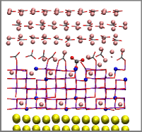
One obstacle facing the deployment of high voltage cathode materials is the apparent anodic instability of organic solvent molecules found in standard electrolytes (Fig 1), such as ethylene carbonate (EC) and dimethyl carbonate (DMC).xu EC and DMC oxidation has been proposed to lead to formation of thin cathode electrolyte interphase (CEI) films.jarry ; borodin_nature ; shkrob2017 ; kanno1 ; kanno2 ; ram_spinel ; oh ; cei_pt ; song ; edstrom ; aurbach01 ; aurbach99 ; novak While the existence of CEI films on cathode surfaces has long been confirmed at modest voltages,edstrom ; aurbach01 ; aurbach99 ; novak questions remain about the origin of CEI species.crosstalk ; crosstalk1 Although extensive spectroscopic and imaging studies have been conducted, the structure and function of CEI on cathode oxide material surfaces remain poorly understood. To complicate matters, transition metal ion dissolution from cathode oxide surfacesram06 and surface phase transformation of layered cathode oxides to form rock saltsdoeff ; interfacetobulk can occur at the same time. Protective coating has been applied with some success.ald0 ; ald1 ; ald2 ; ald3 ; ald4 ; ald5 Electrolytes tailored for high voltages can also circumvent this problem,borodin_nature ; shkrob2017 ; sulfone often at the cost of higher electrolyte viscosity and material expense.
(a) 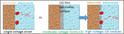
(b) 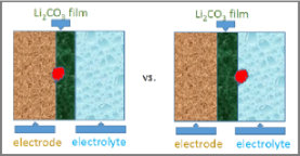
There is increasing experimental evidence that CEI components on cathode oxides are not static; they continue to evolve and/or become further oxidized as cycling proceeds to high voltages.novak ; oh ; matsui ; shendillon1 ; shendillon3 ; amatucci1 ; sargita ; ma This finding is not limited to the cathode side; evolution of SEI physical properties and chemical composition on anode surfaces has also been reported.anode_sei1 ; anode_sei ; batt ; perla Recent differential and online electrochemical mass spectroscopy (DEMS, OEMS) measurements have proven extremely useful for correlating gas release with voltage changes.novak2016 ; gasteiger2018 ; gasteiger2017 ; gasteiger2015 ; gasteiger2014 ; abruna ; janek2016 ; behm The onset of CO2 release from LNMO cells has been reported to be 4.6 to 5.5 V, except for open circuit and first-cycle contributions. CO2 release from layered NMC occurs at lower potentials and has been linked to reactive oxygen release.gasteiger2018
Regarding theoretical modeling, anion-mediated EC oxidation has been predicted to occur in bulk solutions at about 5 V potentials.borodin1 ; borodin17 EC is also predicted to undergo a one-step CO2 release reaction on LNMO (001) surfaces.tateyama However, there is substantial computational evidence that EC and DMC molecules already react with cathode oxide surfaces at more modest voltages,leung1 ; leung2 ; borodin2015 ; giordano1 ; giordano2 ; musgrave1 ; tebbe ; morgan ; bal19 ; li17 ; evenstein ; intan19 ; benedek ; evenstein especially on the surfaces of nickel-free manganese spinels (LiMn2O4, or LMO) which do not normally operate beyond 4.3 V. Strictly speaking, the predicted reactions are interfacial. Long range electron transfer into the liquid electrolyte is not yet predicted; instead direct contact between electrolyte and oxide surfaces is required.note1 These predictions are inconsistent with the view that high voltages are needed to oxidize the electrolyte.
Based on these computational and experimental findings, we adopt an alternative view of high voltage cathode interfacial reactions which has already been suggested for oxidation on Pt surfacescei_pt (Fig. 1a). (1) Solvent molecules in standard organic battery electrolyte first react with cathode oxide surfaces at modest voltages during charging. This occurs even on non-high-voltage materials like LixMn2O4. The oxidation generates adsorbed fragments which, to some extent, “passivates” surface reaction sites. (2) At higher voltages during charging, these CEI products become oxidized and are removed, releasing CO2 gas and leading to uncontrolled further electrolyte decomposition. We argue that the latter event is more responsible for rapid capacity fade (Fig. 1a).
In this work, solvent decomposition products previously predicted to adsorb on LMOleung1 ; leung2 constitute our “CEI” model components. Until these species desorb, dissolves, and/or are themselves oxidized, they should sterically passivate cathode surfaces. We focus on these organic fragments, and omit inorganic CEI components like LiF and LiwPxOyFz, related to PF decomposition. Such inorganic species are presentedstrom ; aurbach01 ; aurbach99 ; zhang2019 ; zhao2019 but neither release CO2 gas nor have been predicted to be oxidized at any reasonable voltages. Indeed, PF decomposition products have been suggested to partially passivate LNMO.novak2016
We apply Density Functional Theory calculations to illustrate the hypothesis (Fig. 1a). We adopt the (001) surfaces of LMO and high voltage spinel LNMO as model systems, and compute the thermodynamics and kinetics associated with degradation reactions. First we re-examine the initial EC oxidation stepsleung1 using the hybrid PBE0 functional,pbe0 which is generally more accurate for reaction barrierspbe_barrier ; wtyang than the DFT+U methoddftu1 widely used in the literature,leung1 ; leung2 ; borodin2015 ; giordano1 ; giordano2 ; musgrave1 ; tebbe ; morgan ; bal19 ; li17 ; evenstein ; intan19 ; benedek but is far more computationally costly. Next we consider the further oxidation of these initial products on LNMO, and show that lower Li and higher Ni contents, which correspond to higher voltages, are needed to lower the reaction barriers sufficiently to activate further reactions that release CO2. Due to the computational cost, PBE0 is only used to examine the key reaction steps. One key finding is that DFT+U can significantly underestimate reaction barriers compared to PBE0, yielding qualitative changes in mechanistic interpretations. Online electrochemical mass spectroscopy (OEMS) measurements are also conducted to support the theoretical results.
Other cathode interfacial evolution phenomena are related to the above discussions. First, the native Li2CO3 film covering most as-synthesized cathode oxide materials must somehow disappear or be ruptured before the elcetrolyte can react with them. It is widely accepted that native Li2CO3 films readily form on cathode oxide surfaces upon exposure to CO2 in air after synthesis.lbl Li2CO3 is known to be oxidized to yield CO2 at 4.2 Vlbl ; luntz or above.gasteiger2013 The carbonate content on CEI films on layered NMC has indeed been reported to fluctuate as cycling continues.matsui ; shendillon1 ; shendillon3 ; amatucci1 ; luntz Some studies suggest Li2CO3 dissolves due to reactions with LiPF6 degradation products like HF.amatucci1 However, Li-air battery studies, which do not involve PF that generates HF, also report Li2CO3 oxidation.luntz ; gasteiger2013 Using the DFT+U method and storage condition experiments, we perform exploratory studies to investigate whether oxidative reactions at the liquid electrolyte/Li2CO3 interface occur more readily than at the Li2CO3/LNMO (001) interface (Fig. 1b). Another interesting phenomenon is one version of “cross-talk” where SEI fragments diffuse from the anode to the cathodecrosstalk ; crosstalk1 and become oxidized.sargita Cross-talk products have variable structures,crosstalk1 and they will not be considered herein. However, the principles and methods used in this work can also apply to study this phenomenon.
II Methods
We estimate mean reaction rates using the standard transition state theory rate equation
| (1) |
where is the activation energy, =1012/s is a standard kinetic prefactor, and is the thermal energy at room temperature. Any step in the proposed reaction mechanisms is considered favorable if it is exothermic (0) and if is less than one hour – which translates into 1 eV.batt Eq. 1 assumes T=0 K and ignores entropy which is small in most cases. As will be discussed, in a few relevant cases gas phase translational or vibrational entropic effects are added post-processing.
and are computed using T=0 K static ultrahigh vacuum (UHV) condition DFT calculations, conducted using periodically replicated simulation cells and the Vienna Atomic Simulation Package (VASP) version 5.3.vasp1 ; vasp1a ; vasp2 ; vasp3 A 400 eV planewave energy cutoff and a 10-4 eV convergence criterion are enforced. Antiferromagnetic ordering is imposed on LixNi0.5Mn1.5O4 and LixMn2O4.
Most DFT calculations herein apply the Perdew-Burke-Ernzerhof (PBE) functionalpbe with the Hubbard (DFT+U) augmentation.dftu1 The and values associated with DFT+U depend on the orbital projection scheme and DFT+U implementation details; here 4.84 eV, 5.96, and 3.30 eV for Mn, Ni, and Co in accordance with the iterature.zhou ; persson14 ; liverpool1 ; islam Co-based materials are discussed only in the S.I. The PBE functional that underlies DFT+U calculations tends to underestimate reaction barrierspbe_barrier because of localization errors.wtyang The hybrid PBE0 functional, generally considered more accurate than PBE for barriers,pbe_barrier is applied to key reaction steps as spot checks.pbe0 Although fewer in number, these PBE0 calculations constitute the main results in this work. See the S.I. for rationale for choosing PBE0 over other hybrid functionals. In slab geometry DFT+U calculations, the standard dipole correction is applied.dipole It is found that this correction is on the order of meV, and it is omitted in PBE0 calculations.
Reaction barriers () are computed using the climbing image nudged elastic band (NEB) method.neb PBE0-based NEB calculations require far more ionic steps than DFT+U NEB. The reason is that, in the relevant oxidative reactions, protons and are transferred simultaneously. The (spatial) radius of convergence associated with PBE0 NEB is small because the being transfered is more localized than in DFT+U predictions. Therefore good initial guesses are needed to converge PBE0 NEB. Using DFT+U NEB configurations as guesses routinely fails to yield PBE0 barriers.
222 and 221 Brillouin zone sampling schemes are adopted for LMO and LNMO bulk and surface unit cells. The DFT+U lattice constants for LMO and LNMO are predicted to be 8.40 Å and 8.30 Å, respectively. PBE0 simulation cells are assumed to have the same cell dimensions. 11 surface cells are created by exposing (001) surfaces.lmo111 ; persson14 ; persson13 ; vitaly The resulting slabs have LinNi4Mn16O40 or LinMn20O40 stoichiometries and no net dipole moment normal to the surface. The slight reduction in the Ni/Mn ratio in our LNMO surface models, compared to the canonical LixNi0.5Mn1.5O4, is the result of using a fairly thin slab.
For the 11 (001) surface cells used, PBE0 is up to 100 times more costly than DFT+U for each ion step. Therein lies the advantage of using a small surface cell: the PBE0 functional can be applied more readily. Furthermore, the energies of all configurations with different Ni positions can be enumerated (at least when using the DFT+U method). With (i.e., under synthetic conditions), it is most energetically favorable to have one Ni on each surface and two Ni in the interior. To check system size effects, some DFT+U calculations associated with the oxidation of EC fragments apply 12 surface supercells along with 211 Brillouin sampling. These results, and justification for using a single adsorbed molecule at T=0 K to model anodic decomposition, are discussed in the S.I.
DFT+U-based vibrational frequency calculations are conducted to confirm that one of the configurations predicted to be a transition state (TST) indeed has only one unstable mode. The frozen phonon method is applied, with only the EC fragment allowed to move. In other words, oxide ions are assumed to be infinitely heavy. The vibrational contribution to the free energy difference between initial and transition states is estimated using a harmonic approximation,
| (2) |
where =initial or TST, =30 or 29 in the two cases respectively, is the th vibrational frequency in the EC fragment, and is Planck’s constant.
Calculations on Li2CO3/LNMO interfaces apply 13 LNMO surface supercells along with 211 Brillouin sampling. More details are provided in the S.I. Reactions between Li2CO3 films and EC molecules apply 221 Brilloin zone zampling, 8.3410.0228 Å3 simulation cells with 16 Li2CO3 units, and 4 Li removed from the surface.
The net electronic spin on each transition metal ion is examined to determine their charge states. Mn(II), Mn(III), and Mn(IV) are identified as Mn ions which exhibit net spins of 4.6, 4.0, and 3.3 (all to within 0.3 unit), as reported by the VASP code using its default PAW orbital settings. For added verification, the maximally localized Wannier orbitial methodwannier is applied to locate the center of all occupied orbitals within 0.3 Å of each transition metal ion. By counting the number of occupied -Wannier orbitals centered around each Mn/Ni, the charge state can be unambiguously assigned.
Regarding experiments: for making the composite electrodes, a uniform slurry was prepared by mixing 84% LNMO, 6% CMC, and 10% C65. The contents were thoroughly mixed using Thinky Mixer (ARV-310/ARV-310LED) at 2000 rpm and 40 kPa for 3 minutes. The prepared slurry was then coated on a clean and polished Al foil using a doctor’s blade adjusted for 60 m thickness. The coated sheet of aluminum foil was then heated at 100oC followed by rolling to ensure complete removal of trapped air or solvent. Vacuum dried electrodes with 12 mm diameter were used for the OEMS study.
For online electrochemical mass spectrometry, the OEMS cells were assembled using Li (14 mm diameter) as anode and LNMO composite electrode (12 mm diameter) as cathode. 2 poly-propylene separators (29 mm diameter) were used between the two electrodes with 100 L of LP30 (1M LiPF6 in EC:DMC (1:1)) electrolyte. The cell was connected to OEMS (HPR-40, Hiden analytical) using a micro-capillary inlet with a sample rate of 12 L/min. The galvanostatic charge/discharge was carried out using VSP- potentiostat (Bio-logic Science instruments) in a potential window of 3.5 V to 5.0 V at a rate of C/10. For the in-operando measurements of the evolved gases as a function of applied potential in the real-time frame, Mid mode was selected for H2 (m/z = 2), CO2 (m/z = 44), and CO and C2H4 (m/z = 28) gases.
III Results and Discussions
III.1 Revisiting EC oxidation on LMO using DFT/PBE0
(e) 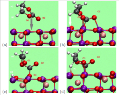
Our previous computational work,leung1 ; leung2 using the DFT+U method, has shown that ethylene carbonate (EC) decomposition occurs readily on LMO (001) and (111). In particular, 40% charged LMO (Li0.6Mn2O4) already oxidizes EC molecules on its (001) surface. The rate-determining, oxidative step releases =-2.0 eV. The reaction barrier is predicted to be only =0.56 eV. According to Eq. 1, a reaction with this small occurs in millisecond time scales. Thus Li0.6Mn2O4, which should operate below 4.3 V, is predicted to rapidly oxidize EC molecules. Higher voltages are not needed. The more accurate PBE0 mehthod has also been used to calculate .leung1 However, PBE0 reaction barriers () have not been previously reported.
Fig. 2 describes new PBE0 predictions computed using the climbing image nudged elastic band method (NEB).neb First Fig. 2a depicts an intact EC on LMO (001) surface. Fig. 2b-d depict the initial, final, and barrier configurations associated with the rate-determining oxidative step in the initial decomposition of EC molecules. Two and a H+ are transferred. is eV, which is only 0.25 eV less exothermic than the DFT+U value.leung1 at the barrier top (Fig. 2d) is found to be 1.05 eV higher in energy than Fig. 1b. This PBE0 is 0.49 eV larger than DFT+U value, in accordance with our expectation that PBE0 barriers are generally higher.pbe_barrier This PBE0 value should be more accurate.pbe_barrier 1.05 eV is still consistent with a fast degradation reaction at room temperature, especially because the large zero point energy (ZPE) correction associated with proton motion has so far been neglected. ZPE contribution at T=300 K can be estimated using DFT+U configurations, DFT+U frozen phonon calculations which yield a single unstable vibrational mode at the transition state, and Eq. 2. We find that ZPE lowers (or more appropriately , the free energy barrier) by 0.16 eV, to only 0.89 eV. This value is consistent with 4 reactions per hour (Eq. 1), well within battery time scales. We conclude that CEI products readily form on moderate voltage LMO (001).
Given the cost of PBE0 barrier calculations, we have not performed the same two , one H+ transfer calculation on LNMO (001). Since LNMO operates at higher voltages, and should yield more exothermic, faster reactions than corresponding ones on LMO, it is reasonable to assume the reactions of Fig. 2 also readily occur on LNMO (001) at the same Li-content.
III.2 Further Oxidation on LMO and LNMO: DFT+U Predictions
As discussed in Ref. leung1, , efforts to break other bonds in this partially oxidized EC fragment (Fig. 2c) have yielded endothermic reactions. Hence this fragment has been assumed to persist during battery charging. However, a hitherto unexamined pathway proves favorable when using the DFT+U method. We stress, particularly to experimentalist readers, that more accurate PBE0 calculations presented in the next section suggest that DFT+U overestimates reactivities. Nevertheless, it is useful to first report DFT+U predictions.
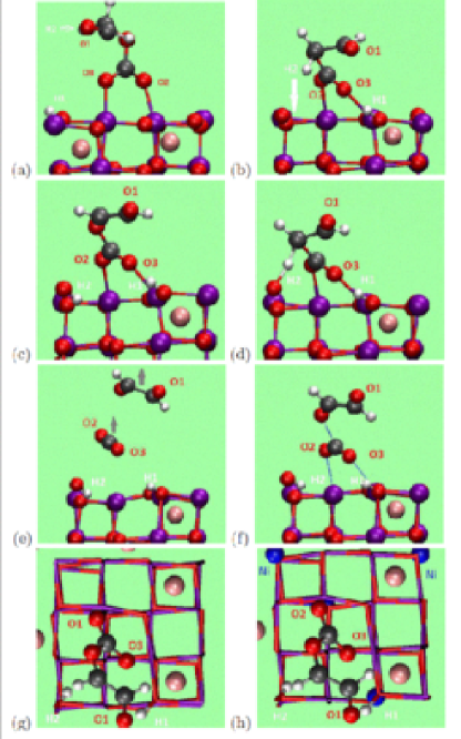
The Fig. 3a configuration spontaneously emerges from Fig. 2c in finite temperature DFT+U-based molecular dynamics simulations,leung1 and involves lifting one O2- anion out of the LMO surface. Static DFT+U calculations predict that it is 0.10 eV more favorable than Fig. 2c. We rotate this organic fragment so one of its H-atoms faces the oxide surface, remove one more Li to partially offset the implicit voltage decrease due to transfer of from EC to the oxide, and use the resulting configuration (Fig. 3b) as the re-starting point.
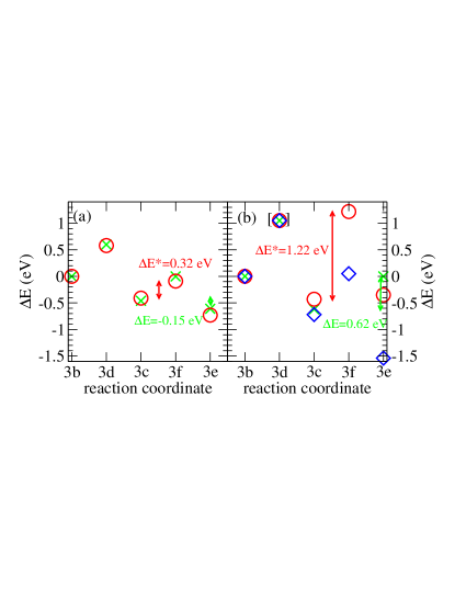
The next favorable step involves the transfer of a second H+ and an to the LMO surface (Fig. 3c). It is exothermic by =-0.46 eV using the DFT+U method (Fig. 4a). The DFT+U transition state (Fig. 3d) exhibits =+0.60 eV relative to Fig. 3b; this value is similar to that in the proton transfer step (Fig. 2d) when using DFT+U.leung1
Once this second hydrogen is transferred, the cleavage of the bond between the carbonyl carbon and an oxygen originally in the EC 5-member ring becomes favorable by =-0.15 eV relative to Fig. 3c according to DFT+U. Breaking this bond leads to the release of both a CO2 and a glyoxal (C2H2O2) molecule (Fig. 3e). Without the prior H-atom transfer step, CO2 elimination would have been accompanied by the release of a CHOCH2O radical, which is less energetically favorable, although a similar reaction appears favorable on LNMO,tateyama not LMO. It results in a 4-coordinated Mn(II) ion in Fig. 3e. The DFT+U-predicted barrier configuration (Fig. 3f) exhibits =0.46 eV relative to Fig. 3c, and has a 1.95 Å C-O bond length. C2H2O2 is known to be a polymerizing agent. It is likely to react either with the oxide surface or other EC molecules in the solvent, and is not expected to be detected after cycling.
DFT+U predicted EC fragment configurations on LNMO (001) are similar to those on LMO (001), and only one configuration is depicted (Fig. 3h). The only qualitative difference with LMO is that the 4-coordinated Mn in the final configuration on LNMO (Fig. 3e for LMO) remains a Mn(III); a nickel ion is reduced instead of a Mn(III) following oxidation of the organic fragment. The final step =+0.32 eV is lower than the corresponding LMO value (Fig. 4). Because the surface Ni introduces heterogeneity with respect to the EC binding site, we have translated the organic fragment in Fig. 3h about the diagonal in the surface cell containing the surface transition metal ions, and find that the configuration depicted is within 0.03 eV of the most stable among 8 choices we have considered.
The main problem with these DFT+U results is that the predicted and for reactions on LNMO surfaces are similar to those on LMO (Fig. 4a). Both oxidation steps subsequent to the LNMO equivalent of Fig. 3c are exothermic, and the average reaction times are much less than one hour. With all adsorbed organic fragments removed from their surfaces, LMO and LNMO should continuously react with solvent molecules and evolve CO2 at LMO operating potentials ( V). Experimentally, CO2 release is observed with LNMO at high voltage, but not with LMO at lower voltages after the first cycle.novak2016 ; gasteiger2018 ; gasteiger2017 ; gasteiger2015 ; gasteiger2014 ; abruna ; janek2016 ; behm DFT+U fails to distinguish LMO spinel and high-voltage LNMO spinel. Doubling the size the the simulation cell and adding more EC molecular fragments does not resolve this discrepancy between modeling and experiments (S.I.). The absence of molecular fragments on the cathode oxide at intermdediate voltages also seems inconsistent with two apparent CO2 onset potentailsnovak2016 (see Sec. III.4 below).
III.3 Further Oxidation on LMO and LNMO: PBE0 Predictions
The PBE0 method is next applied to key reaction steps to distinguish LNMO from LMO. The PBE0-predicted configurations are qualitatively similar to those in Fig. 3, and are depicted only in a few cases. But the energetics are substantially different (Fig. 4b).
First we revisit the transition between configurations Fig. 2c and Fig. 3a, which does not involve electron transfer. At this Li0.6Mn2O4 stoichiometry, DFT+U predicts =-0.10 eV. In contrast, the PBE0 functional predicts that =+0.16 eV. The PBE0 starting and ending configurations are depicted in Fig. 5a-b. It is reasonable to assume that the PBE0 value is more accurate. However, for the purpose of modeling further oxidizing reactions, we should remove more Li atoms to partially offset the transferred from EC to the LMO slab so as to maintain high voltages. Next we eliminate the Li directly coordinated to the surface O2- anion being dragged by the EC fragment off the surface (labeled “O” in Fig. 5c) to yield a Li0.5Mn2O4 stoichiometry. Now the equilivalent of Fig. 5b, but with one less Li, becomes exothermic (=-0.25 eV, not show in Fig. 5) relative to Fig. 5c, suggesting that this step should proceed. The overall Li-removal from Fig. 5a yields a +4.70 V equilibrium voltage if one takes into account lithium metal cohesive energy. (Here “equilibrium” means “electrochemical equilibrium”;leung3 see Fig. 7b below.) Thus a 4.70 V potential appears necessary for further EC oxidation on LMO. By comparison, this requirement is found to be only 4.33 V in DFT+U calculations.
The next deprotonation step (Fig. 3b Fig. 3c) is predicted to be exothermic using both DFT+U and PBE0 functionals (Fig. 4a-b). Since this is another proton transfer, we assume that the PBE0 is not dissimilar to the computed in Fig. 2d for that H-transfer (1.05 eV, bracketed in Fig. 4b), and omit this step from PBE0 consideration.
Instead we focus on the final step. For Li0.5Mn2O4, PBE0 predicts that the Fig. 3c Fig. 3e reaction, associated with CO2 and C2H2O2 release, exhibits =0.62 eV. This is far more endothermic than the DFT+U prediction (Fig. 4a). We speculate that the DFT+U parameter for Mn is fitted to Mn(III)/Mn(IV) solid state electrochemistry and may overestimate the stability of the Mn(II) found in Fig. 3.
Fig. 5d depicts the product of the CO2 release reaction on Li0.5Ni0.5Mn1.5O4, instead of LMO, at the same Li content. While the EC fragment configuration superficially resembles that on LMO surfaces, the presence of Ni makes this reaction far less endothermic (=0.08 eV Fig. 4). CO2 release should be accompanied by the typical favorable entropy of 0.4-0.5 eV at T=300 K at estimated gas pressure of 0.1 atm.,ma which offsets the 0.08 eV endothermicity. In fact, all steps of further EC oxidation we have examined so far with the PBE0 method (Fig. 3, Fig. 5) are more favorable on LNMO (001) than LMO (001) slabs at the same 50% Li content (Fig. 4a). Just by considering energetic differences, the PBE0 functional (unlike DFT+U) already distinguishes oxidation on LNMO from that on LMO.

Next we examine the kinetics associated with CO2 release on LNMO. The predicted at the PBE0 transition state (Fig. 5e) is larger than the DFT+U value by a factor of 3.5 (Fig. 4). Whereas the DFT+U is consistent with a fast reaction, the PBE0 value of =1.22 eV suggests that the organic fragment shown in Fig. 3d should persist over beyond battery operation time scales on Li0.5Ni0.5Mn1.5O4 at T=300 K. (Note that the Fig. 5e transition state does not involve proton transfer, and a large zero point correction is not expected.) We have not repeated the similar reaction on LMO surface because LMO is expected to be even less oxidative than high-voltage LNMO at the same Li content. It is perhaps not surprising that this complex transition state proves problematic for the DFT+U functional. The unusual reaction involves the simultaneous transfer of , breaking of a C-O covalent bond, and the removal of two oxygen-surface metal coordination. In Fig. 5e, the C-O bond distance is 1.71 Å, which is 0.24 Å shorter than the 1.95 Å predicted using DFT+U. More conventional reactions, such as that C-O bond cleavage reaction in CO, exhibit which are less sensitive to choice of hybrid or non-hybrid DFT functional.batt
For CO2 release to occur, the gas molecule must not re-coordinate to the oxide surface. In the PBE0 NEB barrier calculation, we accidentally come across a configuration where the released CO2 adsorbs via another surface O, reconstituting a CO motif (Fig. 5f). This configuration is 0.49 eV more favorable than Fig. 5e at zero temperature. Thus, even with the gas entropy gained at T=300 K, CO2 release from the (001) surface of Li0.5Ni0.5Mn1.5O4 is arguably barely favorable.
Finally, we examine PBE0 predictions at higher equilibrium voltages. We lower the Li-content to 20% (Li0.2Ni0.5Mn1.5O4) (not shown in figures), which should raise the equilibrium cathode voltage. With this change in Li-content, the blue diamonds in Fig. 4b indicate that the last two steps of the reaction are now both exothermic, =-0.72 and -0.82 eV, respectively. The final, CO2-releasing step now exhibits a much lower =+0.77 eV instead of the +1.22 eV at . According to Eq. 1, CO2 release occurs in sub-second time scales at . Furthermore, the Fig. 5f-like CO2-adsorption configuration appropriate to 20% Li content exhibits a weak CO2 binding energy of =-0.36 eV, compared to -0.49 eV at . In other words, as Mn and Ni cations acquire larger charges, O2- anions coordinated to them exihbit weaker covalent bonds with CO2 molecules. This will not retain CO2 on the surface because of the 0.4 eV entropy gain upon gas release at T=300 K at 0.1 atm.ma
In summary, the more accurate PBE0 method predicts that CO2 release is not energetically favorable on LMO (001) surfaces at 50% Li-content. Even on LNMO (001) at the same Li-content, which should represent a higher equilibrium potential than 4.3 V, CO2 release remains energetically and kinetically hindered. Only at lower Li-content (20%, which corresponds to an even higher equilibrium voltage) does CO2 release become fast. The partially oxidized EC fragment is now completely eliminated from the surface (Fig. 5c). Cleared of adsorbed species, the surface can now continuously react with solvent molecules (Fig. 1). Unlike PBE0, DFT+U fails to predict this two-step behavior or to distinguish between LMO and LNMO.
We have not computed the precise CO2 release onset voltage. This is partly because the electronic voltageleung3 is not readily specified in polaronic conductors like LMO and LNMO (see Sec. III.5 below). Other CEI components have been proposed;jarry one of them is examined in the S.I., and found to react at moderate Li-content without releasing CO2.
III.4 OEMS Measurements
To support the theoretical calculations with experimental proofs, we carried out in-operando analysis of gaseous evolution as a function of applied potential using online electrochemical mass spectrometry (OEMS) of LNMO in 1 M LiPF6 in EC:DMC (1:1). The observed evolution of H2, CO2, and C2H4 during galvanostatic charge/discharge is depicted in Fig. 6a.
(a) 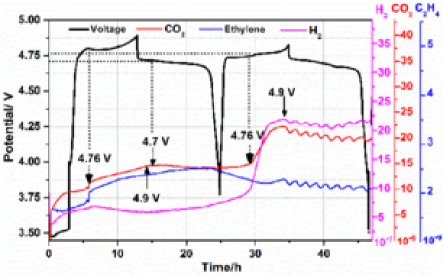
(b) 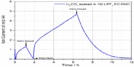
The evolution of C2H4 (=28) at the beginning of first charge is likely associated with the SEI formation at the anode side through reductive decomposition of ethylene carbonate from the electrolytic solution.behm We assigned the evolution trend at =28 to ethylene; however, partial contribution from CO cannot be eliminated. By carefully looking at the CO2 evolution, it can be seen that CO2 starts evolving in the OCV period which can be attributed to the spontaneous reaction between the electrolyte and the electrode. This evolution attains equilibrium during the rest period. During charge to voltages higher than 4.75 V, another evolution of CO2 is observed. A maximum in the CO2 evolution was observed at 4.9 V. It is important to note that in OEMS studies, the system is not washed with inert gas during measurements. This fact enables us to continuously measure in-operando the volatile components in the battery cell, without changing its composition and without stopping cascades of reactions that take place. However, due to this unique approach, remaining gas species are constantly detected (e.g. CO2); hence our discussion always focuses on increase/decrease in evolution and local maxima/minima. During the discharge, when the lithiation level of the LNMO increases and the potential goes below 4.7 V, the release of CO2 is reduced.
The onset of CO2 evolution in the second cycle during the initiation of the second plateau at 4.75 V further confirms the validity of the calculated results; the evolution of CO2 from CEI decomposition occurs mainly at lower Li-content and higher voltage. Note also that our calculations focus on the EC molecule; other electrolyte species present in Fig. 6a, such as DMC, may yield more gas products during CEI formation at lower voltages. H2 also exhibited similar pattern of evolution which indicates close involvement of H+ in the degradation of electrolyte and evolution of CO2. This may also in accordance to the predicted transfer of H+ and electron in the EC decomposition, with the caveat that the contribution of anode side to the H2 formation cannot be differentiated. We apply OEMS with a half cell (lithium counter/reference electrode). While OEMS has obvious advantages, our set-up is arguably not well-suited to pinpoint the source of gases. At least one recent of modification of DEMSbehm seems able to differentiate anode and cathode gas contributions. That work also identifies H2, CO, and CO2 products from the cathode.
Next we address the question of how LNMO surfaces can become exposed to the liquid electrolyte despite the fact that as-synthesized cathode oxide materials tend to be covered with native Li2CO3 films. We perform experiments where Li2CO3 particles are soaked in electrolyte with/without LiPF6. These experiments are performed under storage conditions, without applied voltages. We find that Li2CO3 dissolves in electrolyte solution as well as in pure DMC solvent (in absence of LiPF6 salt) – although the latter is much-suppressed. The dissolution is qualitatively consistent with previous studies.kanno1 ; aurbach00 In the video included in the S.I., the left vial is with 0.1 g Li2CO3 in 20 mL of LP30 electrolyte solution, and the right vial has the same amount of Li2CO3 in 20 mL DMC (no LiPF6). In DMC the Li2CO3 settles down immediately (swirling motion of particles can be seen), whereas it remains suspended for much longer in the presence of LiPF6 (LP 30) indicating more gas bubbles adsorbed to Li2CO3 there, and more chance for dissolution. In neither cases do we see complete dissolution of the Li2CO3, which is likely in excess. This finding suggests that whether native Li2CO3 films on oxide surfaces are removed upon soaking in the electrolyte depend on the initial film thickness and electrolyte composition, including impurities present. Fig. 6b depicts OEMS response of Li2CO3 soaked in LP30 solution; it confirms that CO2 is evolved as a dissolution product.
III.5 Li2CO3 Reaction on LNMO surfaces (DFT+U)
The next two subsections consider oxidation of inorganic Li2CO3 films.lbl They suggest alternative mechanisms of Li2CO3 removal prior to LNMO surfaces reacting with the liquid electrolyte, and complement our work on organic CEI components.
In the S.I., we argue that oxidation of Li2CO3 should initiate at interfaces rather than start from the bulk. Here we first consider the interface between its Li2CO3 (0001)li2co3_1 ; li2co3_2 and LNMO (001). In brief, we find that, to the extent the predicted and permit oxidation reactions, they are consistent with the release of triplet O2 gas, not CO2 gas (Fig. 7a). This is at variance with experimental results.lbl Hence we only highlight one aspect of the results and leave most details to the S.I.
(a) 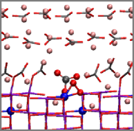
 (b)
(b)
The interface between LNMO (001) and Li2CO3 (Fig. 7a) is Li-deficient, and is likely “metallic.” Fig. S3 in the S.I. confirms the interfacial region has no band gap. Due to this metallic behavior, the electronic voltage () can be readily computed as the LNMO work function modified by its interface with Li2CO3 via the Trasatti relation,trasatti86 ; leung3 ; note2 provided that the electrolyte contribution is neglected. The computed and the voltage based on Li-insertion energetics must match to ensure that simulation cells containing interfaces are at “equilibrium,” not at overpotential conditions. We obtain an electronic voltage of =4.56 V. This value is reasonably close to the 4.75 V found by adding/subtracting Li-atoms. In other words, the model system is not at a significant overpotential. A more general way to compute , even when the electrode has a band gap, is to place an inert metallic electrode underneath.leung3 Upon adding a Au (001) “current collector” (Fig. 7b), is found to an almost indistinguishable 4.58 V. Therefore the metallic nature of the thin interface between LNMO and Li2CO3 should be sufficent for establishing the electronic potential. The of the reaction associated with CO reaction to form O is also very similar to the slab model without the Au slab. This dovetails with our experience that redox reactions on cathode surfaces, which involve discrete changes in occupancies of transition metal ion -orbitals at orbital energies below the Fermi level (S.I.), are not sensitive to ,leung3 unlike reactions on graphitic anodes.leung4 Therefore we have not made further modifications of the interfaces to bring closer to 4.75 V.
There is no metallic character to the LNMO slabs in the previous sections. The cost of PBE0 calculations there makes adding a metallic “current collector” beneath the LNMO (001) difficult, and this impedes effort to calculate . Along with the small cell sizes, this is one reason we have not reported CO2 release onset voltages.
III.6 Reaction between Li2CO3 and Solvent Molecules
Finally, we explore electrolyte oxidative reactions on the outer, partially delithiated Li2CO3 (0001) surface. The PBE functional is applied. As no transition metal ion is present in this section, DFT+U and PBE are equivalent.
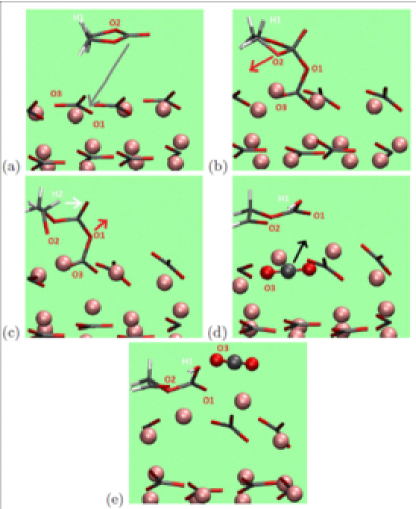
Fig. 8a depicts the (0001) surface with a single physisorbed EC molecule. There should be 8 Li+ on each layer of Li2CO3 in the simulation cell periodically replicated in the lateral dimensions. The top layer has half its Li atoms removed to qualitatively mimic high voltage conditions. The simulation cell remains charge-neutral.
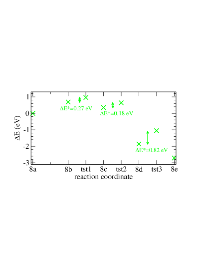
We explore a reaction mechanism similar to that for EC oxidation on LMO (001) (Fig. 2).leung1 In Fig. 8b, the EC is chemisorbed with a bent molecular geometry. This is endothermic by =+0.69 eV (Fig 9). Such a configuration change should exhibit no barrier.leung1 The carbonyl carbon atom is now 4-coordinated. Fig. 8c depicts a subsequent configuration with a broken C-O bond, opening the EC 5-member ring and restoring 3-coordination to what was the carbonyl C-atom. The reaction is exothermic by -0.33 eV compared with the bent configuration (Fig. 8b), but endothermic by +0.35 eV relative to physisorption (Fig. 8a). The barrier is =0.+27 eV relative to Fig. 8b (+0.96 eV relative to Fig. 8a).
The next step is postulated to involve the transfer of a ethylene proton to a nearby oxygen group, in accordance with EC oxidation on oxide surfaces.leung1 Unlike LMO or LNMO (001), O atoms on the Li2CO3 (0001) surface are far away from all protons. When an H-atom is moved from an EC fragment C atom to a surface CO group and the configuration is optimized, we find that the proton spontaneous migrates to an oxygen atom on the ROCO group on the EC fragment instead (Fig. 8d). Simultaneously, a C-O bond is broken, yielding a CO2 on the Li2CO3 surface. This H-transfer step is accompanied by transfer (oxidation) and is overall oxothermic, =-1.86 eV, relative to physisorption. The barrier is =0.18 eV relative to Fig. 8c. In Fig. 8e, the CO2 lodged on the surface is released alongside an additional =-0.84 eV with a local =+0.82 eV barrier. Overall, the highest activation energy among these steps is 0.96 eV. These reactions at the electrolyte/Li2CO3 interface yield more favorable and than at the LNMO/Li2CO3 interface (S.I.).
This reaction pathway represents an alternative to that suggested in Ref. mahne2018, , namely that singlet O2 is released during oxidationwhich then attacks the liquid electrolyte. We stress that this section represents an exploratory plausibility demonstration. We have not exhaustively explored other mechanisms, nor have we applied the PBE0 functional to check . The precise voltage/lithium content relation for this reaction has not been determined. Despite these caveats, this section suggests that EC reactions with surface-delithiated Li2CO3 to release CO2 are viable. Even accounting for possible DFT+U errors, sufficiently high voltage will likely make the EC/LixCO3 reaction sufficiently favorable to occur in one-hour time scales, just like it does for EC fragment oxidation on LNMO surfaces.
III.7 Further Discussions
The further oxidation of our model CEI products involves the simultaneous transfer of H+ and . The role of proton transfer in enabling oxidation of organic components has been emphasized in the presence of counter ions and at multiple battery interfaces;borodin1 ; leung1 ; leung2 ; borodin2015 ; giordano1 ; giordano2 ; musgrave1 ; tebbe ; morgan ; bal19 ; li17 its importance cannot be overstated. One product of our predicted oxidative decomposition is C2H2O2, known to be a polymerizing agent. This appears consistent with polymeric CEI species routinely reported on cathode surfaces,edstrom ; aurbach01 ; aurbach99 although other mechanisms can lead to polymers.
Oxidation of organic molecules and fragments on cathode oxide surfaces inject electrons into transition metal ions therein. To offset this electrochemical reduction and to maintain a constant potential, Li atoms should be removed (with Li+ diffusing into the electrolyte). Ideally, the grand canonical Monte Carlo (GCMC) technique should be combined with DFT calculations for this purpose; so far DFT-based MC is in its infancy.sugino
We propose a multi-step electrolyte oxidation pathway (Fig. 1a), which is also suggested for oxidation on Pt surfaces.cei_pt Electrolytes with fluorinated solvent molecules exhibits increased anodic stability.borodin_nature ; shkrob2017 This behavior is not inconsistent with our hypothesis, because CEI formed from fluorinated molecules should also be more stable against oxidation than CEI formed from standard organic battery electrolytes. This hypothesis is not inconsistent with Ref. tateyama, , which predicts a one-step release of CO2 from intact EC molecules adsorbed on a pristine LNMO (001) surface. Such a direct CO2 release route could take place in a voltage regime where all organic CEI products have been oxidized and removed from LNMO surfaces.
The reported voltage onset associated with CO2 release varies in the literature. He et al.,novak2016 Michalak et al.,janek2016 and Xu et al.gasteiger2014 have reported CO2 release below 5.0 V (4.8 V, 4.6 V, and 4.8 V respectively), while Jusys et al.behm and Jung et al.gasteiger2017 have reported 5.0 V and 5.4 V, respectively. Our reported OEMS results are meant to be a check on this issue. We report 4.75 V (Fig. 6), which is in alignment with Refs. novak2016, ; janek2016, ; gasteiger2014, . The differences may arise from charging rates, anode choices,abraham electrolytes impurities,metzger2016a temperatures, and the initial surface termination of cathode oxide materials. Interestingly, high-Ni content layered NMC materials are reported to release CO2 at much lower voltages than LNMO.gasteiger2017 In another report,novak2016 DMC is found to be more reactive than EC on LNMO. Our calculations have focused on LNMO (001) due to the small cell size that permits PBE0-based calculations, and on EC because we have performed previous studies.leung1 ; leung2 In the future, extending our method to DMC, NMC, counter-ions, ond the (111) facet will give interesting comparisons.
CO release hve been reported at elevated voltages. CO cannot emerge from the mechanism investigated herein, and will be considered in the future.
IV Conclusions
We have applied the hybrid PBE0 DFT functional to compute the energetics and kinetics associated with key steps of interfacial oxidation of model cathode electrolyte interphase (CEI) components on high voltage spinel (LixNi0.5Mn1.5O4 or LNMO) (001) surfaces. Our model CEI components are partially oxidized ethylene carbonate (EC) molecules from previous computational studies.leung1 At moderate Li-content (=0.5), the oxidative reaction barrier is too high. At much lower Li-content (=0.2) which corresponds to higher equilibrium voltages, decreases, and the oxidative reaction occurs within 1-hour battery charging time scales. This leads to removal of adsorbed organic fragments from this surface and release of CO2 molecules. The precise onset voltage cannot yet be determined. Spinel oxides not doped with Ni, i.e., LixMn2O4 (LMO), exhibits reaction energies () far less favorable towards CO2 release compared with LNMO.
We also apply the DFT/PBE0 method to re-examine oxidation kinetics of intact EC molecules on LMO (001) surfaces at 40% charge (=0.6). and for the key oxidative step are predicted to be -1.75 eV and 1.05 eV, respectively, to yield adsorbed species which are the CEI components discussed in the last paragraph. This 1.05 eV barrier is much lower than the for a subsequent CEI oxidation reaction at similar Li-content (=0.5), and is further reduced by zero point corrections.
From these predictions, our PBE0 calculations are consistent with a two-step process. First EC solvent molecules are oxidized at modest voltages and Li-contents. The partially decomposed EC fragment remains on the LMO and LNMO (001) surfaces, covering up the reactive transition metal ion sites. At sufficiently high voltages on LNMO (001), these fragments are oxidized, releasing CO2 gas and clearing the surface for further, uncontrolled reactions with the liquid electrolyte. LMO likely behaves similarly at sufficiently high voltages, but we have not demonstrated this expliclty. Fluoride- and phosphorus-containing CEI products have not been considered in this work.
The widely applied DFT+U method, based on the PBE functional, is useful for predicting qualitative oxidative mechanisms. However, unlike PBE0, it predicts and which are favorable for oxidation of both EC and adsorbed, partially decomposed EC fragments – even at the modest equilibrium potentials associated with Li0.5Mn2O4. This does not appear to agree our online electrochemical mass spectroscopy (OEMS) measurements and those of other groups. This strongly suggests that hybrid DFT functionals should be used to spot-check electrolyte oxidation predictions. Nevertheless, we have used the more economic DFT+U method for an exploratory investigation of oxidation of native Li2CO3 films on cathode oxides. We conclude that oxidation of Li2CO3 is more likely to first occur on the outer Li2CO3 surface in contact with liquid electrolytes, than on its inner surface in contact with cathode oxide materials.
All DFT/PBE0 calculations of the model slabs without Li2CO3 films yield a band gap. Hence there are no delocalized “surface states” – the redox-active states are simply -orbitals localized on surface Mn and Ni transition metal ions. Higher voltages yield more Ni(IV), Ni(III), and Mn(IV) cations and accelerate organic CEI degradation reactions. Two general conclusions that can be drawn from our specific PBE0 functional calculations are: PBE0 is probably more accurate than DFT+U when applied to Mn(II)/Mn(III) redox couple. PBE0 predicts higher reaction barriers associated with C-H and C-O bond-breaking, especially in reactions that releases CO2.
This comparative study on EC, organic CEI component, and Li2CO3 oxidation highlights the importance of multi-step reactions, and emphasizes the need to examine the oxidation of CEI/surface films, not just intact solvent molecules. Differentiating CEI and solvent oxidation events under high voltage conditions should lead to new insights that inform cathode passivation strategies.
Supplementary Material
See supplementary material for simulation cell size effects; the reactions of Li2CO3 on LNMO (001); reactions between EC molecules and other oxide surfaces; oxidation of other proposed CEI components, rationale for using PBE0; rationale for single molecule slab models; optimized PBE0 configurations; and a video showing the reaction between Li2CO3 and liquid electrolytes under storage conditions.
Acknowledgements
We thank Shen Dillon for careful reading of an early draft, and Angelique Jarry, Dale Huber, Jacob Harvey, Katharine Harrison, Christine James, and Yue Qi for useful discussions. MN would like to acknowledge the Funding of Israel science foundation (Grant no. 2028/17 and 2209/17) and support of Planning Budgeting Committee/ISRAEL Council for Higher Education (CHE) and Fuel Choice Initiative (Prime Minister Office of ISRAEL), within the framework of Israel National Research Center for Electrochemical Propulsion (INREP). KL was supported by Nanostructures for Electrical Energy Storage (NEES), an Energy Frontier Research Center funded by the U.S. Department of Energy, Office of Science, Office of Basic Energy Sciences under Award Number DESC0001160. Sandia National Laboratories is a multimission laboratory managed and operated by National Technology and Engineering Solutions of Sandia, LLC, a wholly owned subsidiary of Honeywell International, Inc., for the U.S. Department of Energy’s National Nuclear Security Administration under contract DE-NA0003525. This paper describes objective technical results and analysis. Any subjective views or opinions that might be expressed in the paper do not necessarily represent the views of the U.S. Department of Energy or the United States Government.
References
- (1) A. Manthiram, K. Chemelewski, and E.-S. Lee. Energy Environ. Sci. 7, 1339 (2014).
- (2) T.R. Jow, J.L. Allen, O. Borodin, S.A. Delp, and J.L. Allen. TMS 2014 Supp. Proc. 853 (The Minerals, Metals, and Materials Society, 2014).
- (3) H. Duncan, B. Hai, M. Leskes, C.P. Grey, and G.Y. Chen. Chem. Mater. 26, 5374 (2014).
- (4) Z. Moorhead-Rosenberg, A. Huq, J.B. Goodenough, and A. Manthiram. Chem. Mater. 27, 6934 (2015).
- (5) Xu, K. Chem. Rev. 104, 4303 (2014).
- (6) A. Jarry, S. Gottis, Y.-S. Yu, J. Roque-Rosell, C. Kim, J. Cabana, J. Kerr, and R. Kostecki. J. Am. Chem. Soc. 137, 3533 (2015).
- (7) X. Fan, L. Chen, O. Borodin, X. Ji, J. Chen, S. Hou, T. Deng, J. Zheng, C. Yang, S.-C. Liou, K. Amine, K. Xu, and C. Wang Nature Nanotech. 13, 715 (2018).
- (8) C.-C. Su, M. He, P.C. Redfern, L.A. Curtiss, I.A. Shkrob, and Z.C. Zhang. Energy Environ. Sci. 10, 900 (2017).
- (9) M. Hirayama, H. Ido, K.S. Kim, W. Cho, K. Tamura, J. Mizuki, and R. Kanno. J. Am. Chem. Soc. 132, 15268 (2010).
- (10) M. Hirayama, N. Sonoyama, M. Ito, M. Minoura, D. Mori, A. Yamada, K. Tamura, J. Mizuki, and R. Kanno. J. Electrochem. Soc. 154, A1065 (2007).
- (11) J.-W. Song, C.C. Nguyen, H. Choi, K.-H. Lee, K.-H. Han, Y.-J. Kim, S. Choy, and S.W. Song, J. Electrochem. Soc. 158, A458 (2011).
- (12) There are questions about how much Li2CO3 exists in the CEI. K. Edström, T. Gustafsson, and J.O. Thomas. Electrochem. Acta, 50, 397 (2004).
- (13) M. Moshkovich, M. Cojocaru, H.E. Gottlieb, and D. Aurbach. J. Electroanal. Chem. 497, 84 (2001).
- (14) D. Aurbach, B. Markovsky, M.D. Levi, E. Levi, A. Schechter, M. Moshkovich, and Y. Cohen, Y. J. Power Sources 81-82, 95 (1999).
- (15) T. Yoon, D. Kim, K.H. Park, H. Park, S. Jurng, J. Jang, J.; Ryu, J.H.; Kim, J.J.; Oh, S.M. J. Electrochem. Soc. 161, A519 (2014).
- (16) T. Yoon, T. Lee, J. Soon, H. Jeong, S. Jurng, J.H. Ryu, and S.M. Oh. J. Electrochem. Soc. 165, A1095 (2018).
- (17) F. Simmen, A. Hintennach, M. Horisberger, T. Lippert, P. Novák, C.W. Schneider, A. Wokaun. J. Electrochem. Soc. 157, A1026 (2010).
- (18) S. Fang, D. Jackson, M.L. Dreibelbis, T.F. Kuech, and R.J. Hamers. J. Power Sources, 373, 184 (1028).
- (19) R. Sahore, F. Dogan, and I.D. Bloom. Chem. Mater. 31, 2884 (2019).
- (20) W. Choi and A. Manthiram, J. Electrochem. Soc. 153, A1760 (2006).
- (21) F. Lin, I.M. Markus, D. Nordlund, T.-C. Weng, M.D. Asta, H.L. Xin, and M.M. Doeff. Nat. Commun. 5, 3529, (2014) and references therein.
- (22) L. Zou, Z. Liu, W. Zhao, H. Jia, J. Zheng, Y. Yang, G. Wang, G., J.-L. Zhang, and C.M. Wang. Chem. Mater. 30, 7016 (2018).
- (23) Y.S. Jung, A.S. Cavanagh, A.C. Dillon, M.D. Groner, S.M. George, and S.-H. Lee. J. Electrochem. Soc. 157, A75 (2010).
- (24) X.C. Xiao, D. Ahn, Z. Liu, J.-H. Kim, and P. Lu. Electrochem. Commun. 32, 31 (2013).
- (25) J.W. Kim, D.H. Kim, D.Y. Oh, H. Lee, J.H. Kim, J.H. Lee, and Y.S. Jung. J. Power Sources, 274, 1254 (2015).
- (26) L. Baggetto, N.J. Dudney, and G.M. Veith. Electrochim. Acta 90, 135 (2013).
- (27) Y. Kim, N.J. Dudney, M.F. Chi, S.K. Martha, J. Nanda, G.M. Veith and C.D. Liang. J. Electrochem. Soc. 160, A3113 (2013).
- (28) X. Wang, and G. Yushin. Energy Environ. Sci. 8, 1889 (2015).
- (29) J. Alvarado, M.A. Schroeder, M. Zhang, O. Borodin, E. Gobrogge, M. Olguin, M.S. Ding, M. Gobet, S. Greenbaum, Y.S. Meng, and K. Xu. Materials Today 21, 341 (2018).
- (30) M. Matsui, K. Dokko, and K. Kanamura. J. Electrochem. Soc. 157, A121 (2010).
- (31) C.-Y. Tang, K. Leung, R.T. Haasch, and S.J. Dillon. ACS Appl. Mater. Interfaces 9, 33968 (2017).
- (32) C.Y. Tang, Y. Ma, R.T. Haasch, J.-H. Ouyang, and S.J. Dillon. J. Phys. Chem. Lett. 8, 6226 (2017).
- (33) Z.W. Lebens-Higgins, S. Sallis, N.V. Faenza, F. Badway, N. Pereira, D.M. Halat, M. Wahila, C. Schlueter, T.-L. Lee, W. Yang, C.P. Grey, G.G. Amatucci, and L.F.J. Piper. Chem. Mater. 30, 958 (2018).
- (34) H.-J. Peng. Ph.D Thesis, https://doi.org/10.3929/ethz-a-010793448
- (35) Y. Ma, L .Feng, C.-Y. Tang, J.-H. Ouyang, and S.J. Dillon. J. Electrochem. Soc. 165, A3084 (2018).
- (36) Z. Zhou, P. Lu, C. Delacourt, R. Qiao, K. Xu, F. Pan, S.J. Harris. Chem. Commun. 54, 814 (2018).
- (37) G.M. Veith, M. Doucet, J.K. Baldwin, R.L. Sacci, T.M. Fears, Y. Wang, and J.F. Browning. J. Phys. Chem. C, 119, 20339 (2015).
- (38) K. Leung, F. Soto, K. Hankins, P.B. Balbuena, and K.L. Harrison. J. Phys. Chem. C, 120, 6302 (2016).
- (39) F. Soto, Y. Ma, J. Martinez de la Hoz, J. Seminario, P.B. Balbuena. Chem. Mater. 27, 7990 (2015).
- (40) F.L. Zhang, T.T. Geng, F.F. Peng, D.N. Zhao, N.S. Zhang, H.M. Zhang, and S.Y. Li. ChemElectroChem 6, 731 (2019).
- (41) D.N. Zhao, S.N. Song, X.S. Ye, P. Wang, J. Wang, Y. Wei, C.L. Li, L.P. Mao, H.M. Zhang, and S.Y. Li. Appl. Sur. Sci. 491, 595 (2019).
- (42) M. He, L. Boulet-Roblin, P. Borel, C. Tessier, P. Novák, C. Villevielle, and E.J. Berg. J. Electrochem. Soc. 163, A83 (2016).
- (43) R. Jung, P. Strobl, F. Maglia, C. Stinner, and H.A. Gasteiger, H.A. J. Electrochem. Soc. 165, A2869 (2018).
- (44) R. Jung, M. Metzger, F. Maglia, C. Stinnner, and Gasteiger, H.A. J. Phys. Chem. Lett. 8, 4820 (2017).
- (45) M. Metzger, C. Marino, J. Sicklinger, D. Haering, and H.A. Gasteiger. J. Electrochem. Soc. 162, A1123 (2015).
- (46) M. Xu, N. Tsiouvaras, A. Garsuch, H.A. Gasteiger, and B.L. Lucht. J. Phys. Chem. C 118, 7363 (2014).
- (47) H. Wang, E. Rus, T. Sakuraba, J. Kiluchi, Y. Kiya, H.D. Abruna. Anal. Chem. 86, 6197 (2014).
- (48) B. Michalak, B.B. Berkes, H. Sommer, T. Bergfeldt, T. Brezesinski, and J. Janek. Anal. Chem. 88, 2877 (2016).
- (49) Z. Jusys, M. Binder, J. Schnaidt, and R.J. Behm. Electrochim. Acta 314, 188 (2019).
- (50) L. Xing, O. Borodin, G.D. Smith, and W. Li. J. Phys. Chem. A 115, 13896 (2011).
- (51) O. Borodin, X. Ren, J. Vatamanu, A.v.W. Cresce, J. Knap, and K. Xu. Acc. Chem. Res. 50, 2886 (2017).
- (52) Y. Okuno, K. Ushirogata, K. Sodeyama, G. Shukri, and T. Tateyama. J. Phys. Chem. C 123, 2267 (2019).
- (53) K. Leung. J. Phys. Chem. C 116, 9852 (2012).
- (54) M. Kumar, K. Leung, D.J. Siegel. J. Electrochem. Soc. 161, E3059 (2014).
- (55) O. Borodin, M. Olguin, C.E. Spear, K.W. Leiter, J. Knap. Nanotechnology 26, 354003 (2015).
- (56) L. Giordano, P. Karayaylali, Y. Yu, F. Maglia, S. Lux, and Y. Shao-Horn. J. Phys. Chem. Lett. 8, 3881 (2017).
- (57) T.M. Ostergaard, L. Giordano, I.E. Castelli, F. Maglia, B.K. Antonopoulos, Y. Shao-Horn, and J. Rossmeisl. J. Phys. Chem. C 122, 10442. (2018).
- (58) J.L. Tebbe, T.F. Fuerst, C.B. Musgrave. ACS Appl. Mater. Interfaces 8, 26664 (2016).
- (59) J.L. Tebbe, T.F. Fuerst, and C.B. Musgrave, C.B. J. Power Soures 297, 427 (2015).
- (60) S. Xu, G. Luo, R. Jacobs, S. Fang, M.K. Mahanthappa, R.J. Hamers, and D. Morgan. ACS Appl. Mater. Interfaces 9, 20545 (2017).
- (61) L. Huai, Z. Chen, and L. Li. ACS Appl. Mater. Interfaces 9, 36377 (2017).
- (62) X. Qin, P.B. Balbuena, M. Shao. J. Phys. Chem. C 123, 14449 (2019).
- (63) E. Evenstein, Rosy, S. Haber, H. Sclar, L. Houlen, K. Leung, M. Leskes, and M. Noked. Energy Storage Mater. 19, 261 (2019).
- (64) N.N. Intan, K. Klyukin, V. Alexandrov. ACS Appl. Mater. Interfaces 11, 20110 (2019).
- (65) R. Benedek. J. Phys. Chem. C 121, 22049 (2017).
- (66) Such CEI formation behavior would be distinct from lithium ion battery anodes where parasitic reactions responsible for formation and evolution of solid-electrolyte-interphase surface films often involve long-range electron transfer, and can occur away from electrode surfaces.
- (67) C. Adamo and V. Barone. J. Chem. Phys. 110, 6158 (1999).
- (68) G. Tian, Y. Mo, J. Tao. Computation 5, 27 (2017).
- (69) A.J. Cohen, P. Mori-Sanchez, W.T. Yang. Science 321, 792 (2008).
- (70) S.L. Dudarev, G.A. Botton, S.Y. Savrasov, C.J. Humphreys, and A.P. Sutton. Phys. Rev. B 57, 1505 (1998).
- (71) S.E. Renfrew and B.D. McCloskey. J. Am. Chem. Soc. 139, 17853 (2017).
- (72) N. Mahne, S.E. Renfrew, B.D. McCloskey, S.A. Freunberger. Angew. Chem. Int. Ed. 57, 5529 (2018).
- (73) A.C. Luntz, and B.D. McCloskey. Chem. Rev. 114, 11721 (2014).
- (74) S. Meini, N. Tsiouvaras, K.U. Schwenke, M. Piana, H. Beyer, L. Lange, and H.A. Gasteiger Phys. Chem. Chem. Phys. 15, 11478 (2013).
- (75) G. Kresse, and J. Furthmüller. Phys. Rev. B 54, 11169 (1996).
- (76) G. Kresse and J. Furthmüller. Comput. Mater. Sci. 6, 15 (1996).
- (77) G. Kresse and D. Joubert. Phys. Rev. B 59, 1758 (1999).
- (78) J. Paier, M. Marsman, and G. Kresse. J. Chem. Phys. 127, 024103 (2007).
- (79) J.P. Perdew, K. Burke, and M. Ernzerhof. Phys. Rev. Lett. 77, 3865 (1996).
- (80) F. Zhou, M. Cococcioni, C.A. Marianetti, D. Morgan, and G. Ceder. Phys. Rev. B 70, 235121 (2004).
- (81) J.-H. Kim, A. Huq, M.F. Chi, N.P.W. Pieczonka, E. Lee, C.A. Bridges, M.M. Tessema, A. Manthiram, K.A. Persson, and B.R. Powell. Chem. Mater. 26, 4377 (2014).
- (82) Other DFT+U implementations have been applied to spinel LMO; see I. Scivetti and G. Teobaldi. J. Phys. Chem. C 119, 21358 (2015).
- (83) M.S. Islam and C.A.J. Fisher, C.A.J. Chem. Soc. Rev. 43, 185 (2014).
- (84) J. Neugebauer and M. Scheffler. Phys. Rev. B 46, 16067 (1992).
- (85) G. Henkelman, B.P. Uberuaga, and H. Jonsson. J. Chem. Phys. 113, 9901 (2000).
- (86) The (111) surface should be most prominent, and reconstructed (111) surface models have been devised.persson14 ; persson13 ; vitaly Direct contact betweeh molecules and transition metal ions on the (111) surface will first require creation of oxygen vacancies. The (001) surface, which requires a smaller simulation cell and is commensurate with Li2CO3 lattice constants, is adopted herein for ease of computation.
- (87) E. Lee, K.A. Persson. Chem. Mater. 25, 2885 (2013).
- (88) N.N. Intan, K. Klyukin, V. Alexandrov. J. Electrochem. Soc. 165, A1099 (2018).
- (89) N. Marzari and D. Vanderbilt. Phys. Rev. B, 56, 12847 (1997).
- (90) D. Aurbach, K. Gamolsky, B. Markovsky, G. Salitra, Y. Gofer, U. Heider, R. Oesten, and M. Schmidt, M. J. Electrochem. Soc. 147, 1322 (2000).
- (91) K. Leung and A. Leenheer. J. Phys. Chem. C 119, 10234 (2015).
- (92) Y. Duan and D.C. Sorescu. Phys. Rev. B 79, 014301 (2009).
- (93) S. Shi, Y. Qi, H. Li, and L.G. Hector. J. Phys. Chem. C 117, 8579 (2013).
- (94) The potential should technically also depends on the outer interface between Li2CO3 and the polymeric CEI on top of it, as well as the polymeric CEI/liquid electrolyte interface. The structures of these highly complex interfaces are unknown, and they are neglected herein.
- (95) S. Trasatti. Pure Appl. Chem. 58, 955 (1986).
- (96) K. Leung. Phys. Chem. Chem. Phys. 17, 1637 (2015).
- (97) M.-T. F. Rodrigues, K. Kalaga, S.E. Trask, I.A. Shkrob, D.P. Abraham. J. Electrochem. Soc. 165, A1697 (2018).
- (98) M. Metzger, B. Strehle, S. Solchenbach, and H.A. Gasteiger. J. Electrochem. Soc. 163, A1219 (2016).
- (99) S. Kasamatsu and O. Sugino. J. Phys. Condens. Mat. 31, 085901 (2019).
- (100) D. Qian, Y. Hinuma, H. Chen, L.-S. Du, K.J. Carroll, G. Ceder, C.P. Grey, and Y.S. Meng. J. Am. Chem. Soc. 134, 6096 (2012).