Octagonal Family of Monolayers, Bulk and Nanotubes
Abstract
A new class of tetragonally symmetric 2D octagonal family of monolayers (o-MLs) has emerged recently and demands understanding at the fundamental level. o-MLs of metal nitride and carbide family (BN, AlN, GaN, GeC, SiC) along with C and BP are computationally designed and their stability and electronic structure are investigated. These binary o-MLs show mixed ionic and covalent bonding with the hybridized p states dominating the electronic structure around the Fermi level. Geometric and structural similarity of o-C and o-BN has been exploited to form patterned hybrid o-MLs ranging from metallic to insulating phases. Stacking of zigzag buckled o-MLs results in stable body centered tetragonal (bct)-bulk phase that is suitable for most materials from group IV, III-V and II-VI. Vertically cut chunks of o-BN and o-C bulk or stacking of o-rings, unlike rolling of hexagonal (h)-ML, provide a plausible way to form very thin o-nanotubes (o-NT). Confined and bulk structures formed with an octagonal motif are of fundamental importance to understand the underlying science and for technological applications.
I Introduction
Two-dimensional (2D) monolayers (MLs) are at extreme technological limits for next generation applications. Flat and planar structures have properties and functionalities that can exploit new avenues for research and technological applications. With the technological advent, tremendous interest has emerged in their synthesis and in engineering their properties for applications in electronics, energy storage, high mechanical strength materials and so on. These 2D MLs and their patterned hybrids and multilayered assemblies (graphitic BN, transition metal monochalcogenides and dichalcogenides, silicene, phosphorene) have also gained importance for advanced strain driven technologies (straintronics and twistronics) because of their inherent crystallographic and electronic structural differences. Novoselov et al. (2012); Meunier et al. (2016); Pereira et al. (2009); Naumis et al. (2017) Such 2D materials are reported to show versatile physical phenomena ranging from quantum Hall effect fractal spectrum, reversal of Hall effect, external dielectric environment driven fluctuations in local Coulomb interaction, anomalous spin-orbit torque, etc. on one hand, while applications in 2D electronic devices, spin-polarization switches via strain, giant pseudo-magnetic fields, giant 2D band-piezoelectric effect by biaxial-strain, and so forth on the other. Dean et al. (2013); Liu et al. (2013); Diniz et al. (2017); Ong and Reed (2012); Levy et al. (2010); Xiaomu et al. (2015); Raja and Zhao (2019); Wang and Wang (2019) This demands advancement towards fundamental understanding of existing materials and exploring new possibilities of 2D materials having different structural forms. Predictions of new phases of 2D materials can provide impetus for obtaining exotic properties and possibilities to overcome present synthesis challenges.
Various approaches have been developed to predict new possible allotropes of confined structures based on evolutionary studies, however most of them require considerable computation. De et al. (2011) We have reported octagonal ZnO (o-ZnO) ML through high coordinated cluster assembly route as the next stable plane after the most stable hexagonal ML (h-ML). Gaikwad et al. (2017) This higher coordination fundamental approach provides use of passivating ligands mimicking the bulk-like environment, and demands comparatively less expensive computational process using the ground state geometries of small-sized bare clusters (Xn or AnBn for atom elemental cluster of species X or atom stoichiometric cluster of compound AB). These cluster geometries can be used as building blocks to predict new stable geometries of 2D materials. The geometries of 2D allotropes using pentagons and hexagons as unit building blocks are known and have been studied for various electronic and mechanical properties. Sahin et al. (2009); Zhang et al. (2015a) Pentagons in such works are inspired by the synthesis of pure pentagon based C20 cage and Cairo pentagonal tiling resulting in T12-carbon. The possibility of C in octagonal ML (o-ML) form has also been reported, Liu et al. (2012); Sheng et al. (2012) however the geometry has been chosen differently.
It is known that group IV, III-V and II-VI materials adopt either cubic zinc blende or hexagonal wurtzite crystallographic structures in three dimensions. Many of these have been reported to form hexagonal two-dimensional monolayers. We have formed, for scientifically important group of materials, o-MLs using cluster assembly route. Out of a large pool of investigated materials, ZnO, C, BN, SiC, GeC, AlN, GaN and BP have shown the possibility to form stable o-MLs. Most of the o-MLs of various materials, proposed in the present study, are known to have hexagonal 2D allotropes as their ground state. Topsakal et al. (2009); Sahin et al. (2009) Our preliminary calculations for the o-MLs of BAs, AlP, MoS, CdO, CdS, CdTe, CN, CuO, GaAs, GaP, InN, CdTe, LaN and LaO have not shown dynamical stability. Some recent reports have suggested that o-MLs of N, P, B, As, Sb, BAs and AlP are possible stable structures. Zhang et al. (2015b); Brown and Shuford (2016) however our phonon dispersion calculations suggest that those are dynamically unstable planes. To further investigate fundamental aspect of evolution, we have formed bulk phases by stacking respective stable o-MLs. This body centered tetragonal (bct)-bulk phase is found to be stable for all proposed o-MLs. The most stable and experimentally easy to cleave o-MLs of C and BN are further exploited to form nanotubes and they appeared to be dynamically stable and show metallic and semiconducting nature respectively.
II Computational details
Density functional theory (DFT) Hohenberg and Kohn (1964); Kohn and Sham (1965) based first principles calculations are performed using Vienna ab-initio simulation package (VASP). Kresse and Hafner (1993, 1994); Kresse and Furthmüller (1996a, b) Plane augmented wave (PAW) method Blöchl (1994) as implemented in VASP is used with exchange-correlation energy functional proposed by Perdew, Burke and Ernzerhof (PBE) within the generalized gradient approximation (GGA). Perdew et al. (1996, 1997) A 15151 mesh of -points is used for primitive cell (8 atoms) of h- and o-MLs while 771 and 551 sized meshes are used for 221 (32 atoms) and 331 (72 atoms) supercells of o-MLs of BN containing defects and/or dopants respectively. For the bulk structures and nanotubes, 151515 and 119 -point meshes are used respectively. In all calculations vacuum of at least 18 Å is maintained along the z-direction for planar structures (in the xy-planes) while along x- and y-directions for nanotubes (oriented along z-direction). The electronic energy and ionic forces are converged up to 10-4 eV and 10-3 eV/Å respectively for all calculations.
The vibrational spectra calculated at and phonon dispersion spectra of respective unit cells, using Phonopy code Togo and Tanaka (2015), are used as a first filter to explore the stability of o-ML structures. After that a 3 3 1 supercell is used for phonon dispersion calculations for planes and 113 supercell is used for nanotubes to confirm the dynamical stability and to calculate thermal properties and phonon partial density of states.
Cohesive energy (Ec) of a given ML is calculated using Eq. (1), where E is the total energy of o-XY with atoms of X and Y species. EX and EY are energies of isolated X and Y type of atoms respectively. Ec/ is the cohesive energy per pair (Ec/XY) and is twice Ec/atom. Positive value of Ec indicates stable o-ML structure formation.
Substitutional energy (Esub) to substitute atoms of species Y by species T is calculated using Eq. (2). The term E refers to the energy of the structure with substitution of atoms of species T for species Y, whereas E is the energy of pristine structure. More positive values of Esub represent comparatively higher stability of the substituted structure. Cleavage energy with respect to respective o-bulk phase is defined by Eq. (3), where the terms Eo-ML and Eo-bulk refer to the respective total energy per XY pair of o-ML and o-bulk phase. The o-bulk phase is the optimized structure obtained after stacking o-MLs.
| (1) | |||||
| (2) | |||||
| (3) |
III Results and Discussion
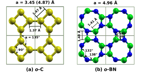
2 2 1 supercells of o-MLs of C and BN are shown in Fig. 1. Similar to h-ML structure, the o-ML structure is a 3 coordinated planar structure. o-BN can be viewed as the structure formed out of combination of passivated cluster geometries obtained from ground state geometries of B2N2 and B4N4 clusters. All the reported o-MLs in this work are designed using cluster assembly route as reported in our earlier work. Gaikwad et al. (2017) The planar structure of o-ML of C belongs to P4/mmm (123) while that of BN belongs to P4/mbm (127) tetragonal space group. As evident from Figs. 1 (a) and (b), o-ML of C is a more symmetric structure. o-ML structure can be viewed as the structure formed out of planar arrangement of octagonal rings (passivated cluster geometry of C8 separated by 1.47 Å in case of o-C and that of B4N4 separated by 1.48 Å in case of o-BN). The bond angles inside the octagonal region are not exactly 135∘ and those inside the square region are not exactly 90∘ for o-BN, as is the case for o-C. These facts generate asymmetry in the crystal structures of various binary compounds and restrict the choice of elements.
| System | Ec/XY | Eclv/XY | Eg | a | d | |
|---|---|---|---|---|---|---|
| (eV) | (eV) | (eV) | (Å) | (Å) | (in degree) | |
| Graphene | 15.98 | 0.02111 The cleavage energy of graphene is with respect to the graphite structure | 0.00 | 2.47 | 1.43 | 120.0 |
| C | 14.95 | 0.14 | 0.00 | 4.87222 The lattice parameter of o-ML of C is defined in terms of 8 atom tetragonal unit cell while the primitive cell lattice parameter is 3.45 Å | 1.37, 1.47 | 135.0 |
| SiC | 11.48 | 1.16 | 4.06 | 6.09 | 1.75, 1.81 | 132.8-137.2 |
| GeC | 9.32 | 1.08 | 1.72 | 6.45 | 1.84, 1.92 | 134.8-135.2 |
| BN | 13.57 | 0.08 | 4.13 | 4.96 | 1.41, 1.48 | 132.2-137.8 |
| AlN | 10.16 | 1.11 | 2.86 | 6.16 | 1.76, 1.83 | 133.1-136.9 |
| GaN | 7.64 | 0.93 | 1.82 | 6.42 | 1.83, 1.91 | 134.9-135.1 |
| BP | 9.41 | 0.98 | 0.79 | 6.35 | 1.82, 1.89 | 134.8-135.2 |
The stability of these structures is studied by investigating structural, energetic and dynamical stability. Table 1 lists the Ec per pair, optimized lattice parameter (refer to SI for typical graph for o-GaN), bond lengths and bond angles of respective stable o-MLs. Here in the table and at other places in this report, results for graphene have been included for comparison. These results agree with the corresponding results published earlier in the literature. ¿From the table it is clear that among all planes, o-ML of BN is the next stable structure after C and it has bond lengths close to graphene. Among each family of carbide and nitride, stability decreases and bond length increases with increasing Z. o-ML of GaN has least Ec although it has comparable Z and lattice parameter with GeC. This can be attributed to asymmetric sp2 hybridization in GaN. Table 1 lists the respective cleavage energy per pair (Eclv/XY) of various o-MLs from their respective o-bulk structures. Lower cleavage energy of 0.14 eV and 0.08 eV for o-MLs of C and BN from respective bulk structures suggests strong possibility of experimental cleavage.
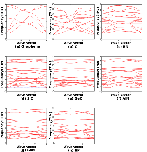
The calculated phonon dispersion spectrum for graphene is shown in Fig. 2 (a). The lower frequency modes are acoustic (ZA, TA, LA) modes while higher frequency modes are optical (ZO, TO, LO) modes. The calculated degenerate LO and TO modes of graphene at are around 1600 cm-1, which are in agreement with previously reported theoretical and experimental values. Sahin et al. (2009); Lee and Martin (1997); Narasimhan and de Gironcoli (2002); Yan et al. (2008) The phonon dispersion spectra of o-MLs of C, BN, SiC, GeC, AlN, GaN and BP are shown in Figs. 2 ((b)-(h)), while respective partial density of states (PDOS) contributed by the constituent atoms can be found in SI. To include large wavelength modes of phonons, a 3 3 1 unit cell is chosen in all cases. It shows minor soft phonon modes in some cases. The imaginary frequencies around point and their extent for acoustic modes can be an artifact of limited accuracy of the calculations. It is known that for 2D confined systems the bending branch ZA can easily become soft and hence may show imaginary frequencies, this however contributes negligibly to the thermal conductivity. Klemens (2001) The soft phonon modes causing instability in the o-ML structures reflect the stress induced in the o-ML. These may be related to significantly different hybridization of deep lying electronic states as well as the electronic states lying near the Fermi energy, in comparison to the stabilization mechanism in respective bulk structures, as will be discussed in subsection III.1. As a result, such o-MLs show significantly different properties. Structures, which show soft phonons, are expected to be more stable in multilayer form. It is indeed reported earlier for o-ZnO. Gaikwad et al. (2017)
All the o-MLs of binary materials belong to tetragonal space group P4/mbm (127) and symmetry of the structure demands crossing of ZA and OA modes at symmetry points K and X resulting in degenerate states along K - X path. Among the o-MLs studied, C and BN are the most stable. o-MLs of SiC and GeC are dynamically stable and those of AlN and GaN show soft phonons. The phonon dispersion spectra for unit cell of o-ML for various materials are provided in supporting information. It is seen that o-MLs of BN, AlN, GaN, BP, GeC, SiC, C are stable. However, for long wavelengths, o-MLs of BP and GaN show soft phonons (Figs. 2 (g) and (h)). Recently, o-ML of GaN and its bulk structure are reported to show no soft phonons (calculated using SIESTA code). The reported optimized bond lengths are marginally greater than those found in the present work but the cohesive energy per atom found in present work suggests a structure more stable than reported earlier. Camacho-Mojica and López-Urías (2015) In the present work, initial guess for geometry is chosen based on trial run of respective passivated clusters. Initial guess is critical since optimization process is complex and difficult due to shallow minimas in the potential energy surface. The phonon dispersion spectrum of o-ML of GaN primitive cell (refer SI) is qualitatively in agreement with the previous reports Camacho-Mojica and López-Urías (2015), however calculations of phonon spectra using 3 3 1 supercell shows soft phonons governed by ZA modes as shown in Fig. 2 (g). The phonon PDOS plots of o-MLs of C, SiC and GeC (refer to SI) clearly show that the induced softening of ZA is caused by heavier atoms and it increases with atomic number. Similar results can be seen for nitride family (refer SI). Since the force constant increases with atomic number, the lighter elements contribute dominantly to the high frequency modes. The structures which are not stable at longer wavelength phonon modes can become more stable if defects are introduced to restrict the propagation of modes.
It is to be noted that structures containing the lighter first row elements (B, N, O) prefer to form more stable planar o-MLs. Similar observations are reported for hexagonal structures and other carbon allotropes. Sahin et al. (2009) The elements having s and p valence states can comparatively easily form planar bonds and therefore form stable o-MLs. Non-planar hybrid states of p, d or f may give rise to dangling bonds. One way to overcome this problem is by inducing buckling in the structure, which allows such z-directional states to form bonds and hence increase the stability of the structure. However, in o-ML structure, the geometrical flexibility of such buckling is restricted to few choices. One possibility corresponds to buckling of alternate pairs of atoms along z-axis in opposite directions by equal amount leading to bulk T-carbon or bct-C4 structure. Umemoto et al. (2010) Another possibility is zigzag buckling of alternate atoms of octagon (4 up and 4 down), known as bct-C8 structure. It amounts to stacking of two planes which are mirror images of each other to form bilayer. It may lead to a bulk phase as discussed in subsection III.3. The same bulk phase can be obtained by stacking nanotubes as explained in subsection III.4.
Both, planar and buckled o-Ge and o-Si are energetically stable but are dynamically unstable. Surprisingly, these octagonal planar structures, though consisting of single type of atoms from group IV, show inherent ionicity.
With increase in the atomic number the force constant decreases, which is compensated by stronger bonding and decrease in the bond length. This is confirmed by the observed variation in the phonon DOS with atomic number. However, with increase in atomic number the ionic radius increases which demands higher lattice parameter for stability, particularly at the square part of o-MLs. Since these criteria cannot be fulfilled by transition metals (higher Z, presence of z-directional states and higher ionic radius) they do not form stable o-MLs. However, we argue that two or more layered assemblies of such materials can lead to displacive phase transition led stable structures. Indeed this is observed in our previous reported work on o-ZnO. Gaikwad et al. (2017) The bulk form T-carbon or Haeckelite structures can be useful in this direction.
Thermal properties viz. Helmholtz free energy, entropy and specific heat of various o-MLs are calculated and are incorporated in supporting information. It is evident that the crossover of specific heat with entropy shifts to higher temperature with the stability of the structure as reflected by respective Ec. It may be noted that with increase in atomic number, the crossover temperature decreases. Thus the stability inferred from Ec, phonon dispersion plots and atomic numbers of constituent materials agree with the decrease in the crossover temperature.
III.1 Electronic structure of o-MLs
Figure 3 depicts the electronic band structure of o-MLs. The electronic structures of graphene and o-ML of C and BN agree with respective previous reports. Liu et al. (2012); Brown and Shuford (2016); Shahrokhi et al. (2017) The band structures show that states around Fermi energy are principally constituted by the p states, in particular the states, of the constituent elements. The strength of the bonding and antibonding, and , states depends on the distance between the parent atoms. If one of the element in the structure is from the first row, size of the atom is small and therefore strong bonds exist in the system. In ionic materials, the states mostly lie on the same atom, the degeneracy of states is lifted and the valence and conduction bands separate giving finite band gap. Charge transfer and hence ionicity decreases with increasing Z. Thus hybridization of states plays a dominant role and changes with Z and size of atom resulting in different electronic properties.

The Dirac cone of graphene is shifted towards lower energy for o-C and this results in metallic nature. All other structures show a finite band gap in the range of 4 to 0.8 eV as shown in Table 1. BN, SiC, GeC and BP show direct band gap while AlN and GaN show quasi-direct band gap. GeC, AlN and GaN have band gap in the visible range and hence can be promising candidates for photo-electronic applications. Furthermore, with introduction of impurities, defects or doping and stacking of layers, the band gap is likely to decrease and can be tuned; in particular the large band gap (4 eV) of BN and SiC is interesting. o-ML of C is energetically the most stable and shows large number of conducting states at Fermi energy in comparison to graphene (Figs. 3 (a) and (b)). This makes o-ML of C a preferable candidate for applications wherein higher conductivity is required. On the other hand, large stability (evident from Ec, phonon dispersion spectrum and thermal properties) and in-built band gap makes o-ML of BN an excellent candidate for applications wherein large band gap is required. Moreover, considering the nearly equal binding energy and lattice parameter of o-ML of C and BN, the band gap of o-ML of BN can be further tuned by C doping and is discussed in subsection III.2.
Charge density plots and Bader charge analysis of o-MLs confirm strong covalent nature of o-C and ionic nature of o-BN. o-BN is ionic because B, with low electronegativity, prefers to donate three valence electrons (QB = +3) while N accepts average charge (QN) of -3e. The N sites of octagonal geometry are less symmetric compared to graphene-like hexagonal structure and have either -2.89e or -3.11e charge on alternate near neighbor N atoms. We ascribe this asymmetry to asymmetric bonding of p states in the xy-plane. As expected o-C is covalently bonded but there is a small charge transfer on alternate near neighbors. This may likewise be due to asymmetric sp2 bonding (refer to SI for details). However, mention may be made that each C8 ring is overall neutral. The actual value of charge transfer may be in error as is well-known for graphene. theoretical chemistry code forum (2011) We have seen similar charge transfer in graphene and o-C but o-C being less symmetric, we expect some ionicity in bonding. To verify further, we have investigated ionicity of dynamically unstable o-Si and o-Ge. As expected, both o-MLs show partial ionicity in bonding. Similar to o-C, Ge shows small charge transfer on alternate atoms and is covalently bonded, while o-Si is highly ionic with charge transfer as high as 1.3e. Although o-Si is dynamically unstable, the calculated ionicity, as high as ZnO, makes it important for hydrogen storage and water splitting applications and needs attention. Camacho-Mojica et al. have shown in their work on hexagonal and Haeckelite GaN that the charge transfer between Ga and N is not much different in the two cases. Camacho-Mojica and López-Urías (2015) We therefore expect the same to hold for the o-MLs studied in this work.
III.2 Hybrid o-MLs of BNC
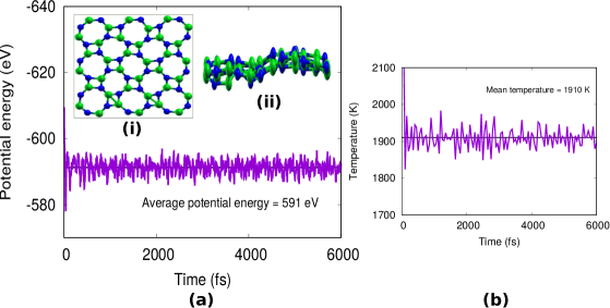
To investigate thermal stability of o-ML of BN, an ab-initio canonical ensemble MD simulation using Nos-Hoover thermostat, as implemented in VASP, is performed. A 3 3 1 (72 atom) supercell of o-ML of BN is used. The thermal stability is seen up to 1900K, wherein the temperature of the system is varied in steps of 100K to save the computational efforts. The o-ML of BN is simulated for 6 ps in steps of 1 fs at 1900K. The final structure is found to be distorted but the basic skeleton of the structure remains the same as shown in insets (i) and (ii) of Fig. 4 (a). Variation of potential energy (in eV) and mean temperature (in K) of the system with time (in fs) are shown in Figs. 4 (a) and (b) respectively. The average potential energy is -591 eV amounting to 0.50 eV per BN pair higher than the planar structure of o-BN. On ionic relaxation of the distorted structure, it forms symmetric planar structure. Thus, phonon and ab initio MD calculations indicate that o-BN possesses very high thermodynamical stability. Stacking of o-MLs is possible due to van der Waals bonding.
BNC hybrid structures are potential candidates as intercalation material for Li-ion batteries. We have therefore studied various possible 2D octagonal structures of BN and C. Three types of doping viz., substitutional, interstitial and adsorption are possible for monolayer. The stability of o-ML of BN is investigated for various doping and defect studies and results are discussed in supporting information. Considering all the types of doping and defects, it is clear that o-ML of BN has very high structural stability and hence it can be synthesized experimentally. Higher structural open space and inhomogeneity compared to h-ML should promote o-ML of BN to be a potential candidate for hydrogen storage applications, gas sensing and dielectric materials applications. It is found that doping of C is energetically favorable only as substitutional doping of C8 octagonal ring. Ci et al. have experimentally investigated h-BNC. Ci et al. (2010) Their results indicate two different band gaps for the hybrid structure corresponding to h-BN and graphene and they have concluded that the two phases are thermodynamically immiscible separating in 2D domains. Larger domains are preferred via decrease in total interfacial domain energy. Experimentally observed structure is kinetically stabilized through non-equilibrium growth process. Theoretical calculations by Yuge depicted strong preference for neighboring B-N and C-C bonds while B-C and C-N bonds are not favored. Yuge (2009) No B-B and N-N bonds are formed. These experimental and theoretical results are for h-BNC and our results for o-BNC are similar. The preference for substitution of octagonal rings suggests agglomeration tendency. Indeed, such agglomeration of C is experimentally observed. Ci et al. (2010) Covalent bonding in case of o-ML of C and ionic bonding in case of BN also play dominant role in doping preference and will be discussed subsequently.
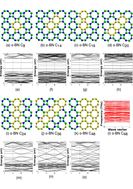
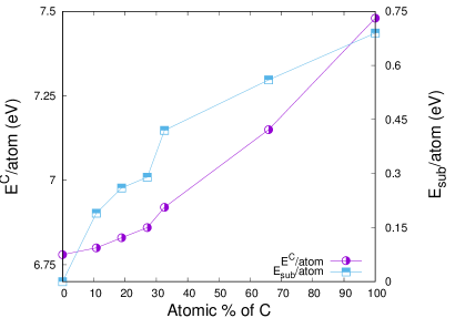
The lattice parameters and bond lengths of o-MLs of C and BN are close to each other, hence it is expected that the two can accommodate each other easily without leaving strain in patterned hybrid assemblies. o-ML of BN is substitutionally doped with the units of C8 rings. The substitution of atomic % of C is varied from 0-100 and minimum energy geometries thus formed are shown in Figs. 5 (a-d) and (i-k). As expected, the C rings can be easily accommodated. Dynamic stability of all the hybrid assemblies is confirmed. To illustrate, phonon spectra of o-BN-C48 hybrid is shown in Fig. 5 (l); it has no negative frequencies and conforms the stability of hybrid structure. Figure 6 depicts the variation of cohesive energy (Ec) and substitutional energy (Esub) per C atom on substitution of C rings. The Ec per atom is found to monotonically increase with concentration of C. For pristine BN, the value is 6.78 eV and it increases till 7.48 eV for o-ML of C. Substitutional energy per C is also found to increase with concentration of C and it is highest for o-ML of C. This increase in stability can be ascribed to covalent bonding of C-C atoms. The concentration of C also influences the band gap (Eg) of the hybrid assemblies (4.13 eV for o-BN to metallic nature for o-C) as shown in Table. 2. The patterns shown in Fig. 5 indicate that for concentration below 30% (up to o-BN-C20), the C rings are confined and this confinement leads to appearance of discrete p states of C in the forbidden region of o-BN. For higher percentages, the structures have translational symmetry in one direction. Of these, o-BNC36 shows the least gap because of incomplete BN rings.
The effect of C loading on electronic structure of o-BNC hybrid assemblies is seen in the band structures incorporated in Figs. 5 (e) to (h) and (m) to (o). The deep lying bands around -18 eV (not shown here) are mostly contributed by and states of N. For pristine BN, valence band (VB) states, from -1 eV to -8 eV, are composed of hybrid p- states of B and N, whereas conduction band (CB) states are dominated by hybrid states of states of N and s states of B. For hybrid assemblies, the bands near the Fermi level (in the gap region of o-BN) are mostly contributed by states of electrons in C rings and this contribution increases with C loading. Larger size of octagonal ring in comparison to hexagonal ring and interaction with interfacial BN states hinders the delocalization of states of C and reduces the band gap to 1.64 eV for o-BN-C8 (Fig. 5 (e)). For the o-ML of BNC hybrids with more than 30% C substitution (o-BN-C36 and o-BN-C48), translational symmetry along one direction (ribbons) diminishes the band gap. The band gap of the hybrid structures is seen to depend on the number of B-C and N-C bonds in addition to number of C rings. The states in the forbidden region are governed by delocalized states of C rings and interfacial B-C or N-C hybridized states. The charge density plots for hybrid assemblies are shown in supplementary information.
| Eg | QB | QN | Q | QC | Q | Q | |
|---|---|---|---|---|---|---|---|
| -BN | 4.13 | 3.0 | -3.0 | - | - | - | - |
| C8 | 1.64 | 3.0 | -2.98 | -2.82 | -0.09 | 0.64 | -0.82 |
| C14 | 1.18 | 3.0 | -2.97 | -2.79 | -0.07 | 0.51 | -0.65 |
| C16 | 0.92 | 3.0 | -2.97 | -2.87 | -0.05 | 0.55 | -0.22 |
| C20 | 1.19 | 3.0 | -2.95 | -2.75 | -0.07 | 0.54 | -0.68 |
| C24 | 1.07 | 3.0 | -2.96 | -2.84 | -0.04 | -0.80 | 0.72 |
| C36 | 0.16 | 3.0 | -2.84 | -2.48 | -0.08 | 0.60 | -0.78 |
| C48 | 0.60 | 3.0 | -2.91 | -2.82 | -0.02 | -0.73 | 0.52 |
| -C | - | 0.15 | -0.15 | - | - | - | - |
Substitutional doping of C rings in BN makes C atoms of the ring to adopt some ionic nature which varies with the environment namely the arrangement and number of rings. In all the hybrid and pristine structures, B atoms donate electrons and possess charge QB equal to +3e. In case of substitution of C8 ring, average charge QN on N atoms varies from -2.82 to -3.02e with an average value of -2.98e. The least charge is on N atoms at the interface which are connected to C atoms. Interestingly, C8 ring does not remain neutral because of the presence of B and N atoms. Further the ionicity increases with higher confinement. The C atoms connected to B atoms possess 0.64e average charge while those connected to N atoms show -0.82e charge. Overall average charge is -0.72e per C8 ring rather than being neutral in pristine o-C. The difference in charge transfer among C atoms (each C atoms possess either +0.64e or -0.82e) is due to the fact that, each interface C atom is triply coordinated with two carbon atoms and the third atom is either B or N of the host.
Substitution of C8, C14, C16 and C20 rings are two dimensionally confined systems. Among them, substitution of C14 and C20 form diagonally confined hybrid structures while C16 is axial substitution as shown in Figs. 5 (b), (d) and (c) respectively. In case of o-BNC16 system, a large variation is seen in charge transfer to/from C atoms connected to N atoms; one of the C atoms has charge 0.66e while for others it varies from -0.6 to -0.71e. For this system the charge transfer from C to N atoms is also seen to be least namely -0.22e. o-BN-C16 is the only system that has a complete square of C atoms that too is confined. When the substitution of C rings is in the form of infinite strips as shown in Figs. 5 (i) and (k), the average charge on C atoms which are connected to interfacial B and N atoms is reversed in sign, as shown in Table 2. It is worth mentioning that there is a large variation in the charges on individual C atoms from -0.8 to 0.72e. In case of o-BNC48 doping, the situation is almost reversed and it can be perceived as single octagonal strip of B4N4 rings substituted in o-C, as shown in Fig. 5 (k). Similar to that of o-BNC24 system, the values of Q (-0.73e) and Q (0.52e) are reversed in sign. However, the respective values of Q and Q are uniform for each atom, as shown in Table 2. This is compensated by variation in the charge of non interfacial C atoms from 0.52 to -0.73e with most of the C atoms covalently bonded. For the system with substitution of infinite strip along diagonal, that is in the case of o-BNC36 system, the interface N atoms are least ionic and also contain non-complete rings of BN. Hence it is not energetically favored as reflected by cohesive energy per atom. The charge density plots suggest that no large charge agglomeration happens at the interface of C - BN rings. Due to higher difference in electronegativity of C and B in comparison to that of C and N, 0.5e of charge is transferred from B to C at interfaces and hence B-C bonds at the interface are more ionic in nature than N-C bonds. Although there is large variation in charge transfer to individual atom depending on the environment, the average charge on each of B, N and C atoms does not vary much.
III.3 Body centered tetragonal structure of o-bulk
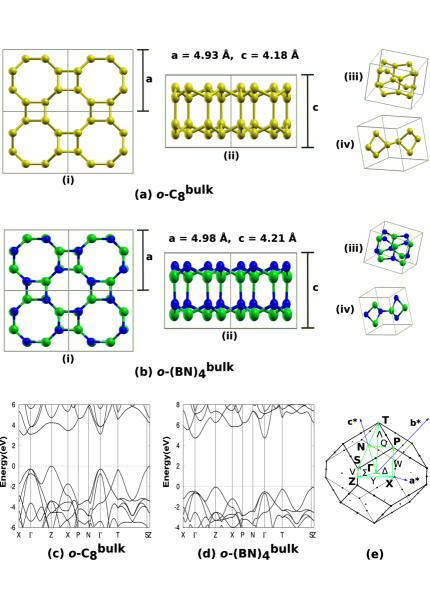
As discussed earlier, two types of buckling are possible in the stacked o-MLs and these generate two possible bulk phases of bct-carbon; one with buckling of pairs of carbon atoms (bct-C4) Umemoto et al. (2010); Liu et al. (2012) and other with the zigzag buckling of carbon atoms (bct-C8), henceforth referred to as o-C. The bct-C8 phase is also known as Haeckelite Camacho-Mojica and López-Urías (2015); Brown and Shuford (2016) bulk structure. Both the phases are from tetragonal family. A third bulk structure bcc-C8 has been reported in the literature Liu et al. (2008); Johnston and Hoffmann (1989). We have found that the total energy per carbon atom of o-C is 0.11 eV lower than that of bcc-C structure. The body centered tetragonal structures of o-C and o-(BN) belong to I4/mcm (140) and I4cm (108) group respectively. The zigzag buckling scheme in the form of octagonal structure (16 atoms) for carbon and boron nitride are shown in Figs. 7 (a) and (b) while primitive cells (consisting of 8 atoms) are shown in (a) (iii) and (b) (iii) respectively. The bct-C4 phase of carbon atom is well documented Umemoto et al. (2010); Liu et al. (2012) and has been a matter of interest due to its ability to form stable o-ML structure. Liu et al. (2012) On similar lines, o-C and respective monolayer phases have been reported for various B and Al pnictogen (X8Y8, X = B, Al ; Y = N, P, As, Sb) and GaN. Brown and Shuford (2016); Camacho-Mojica and López-Urías (2015) In the present work, we have investigated bct-bulk (o-C) phase of carbon which to the best of our knowledge has not been reported in the literature. Our preliminary studies indicate that all the stable 2D o-ML structures reported in the present work form stable bct-bulk phase. We would like to point out that the converse is not true in general namely, known stable bct-bulk phase of binary compounds (from III-V and II-VI groups) may not result in stable 2D structures. Brown et. al and Camacho-Mojica et. al have reported stable bulk-bct phases and respective 2D monolayers of B and Al pnictogen and GaN respectively, but our work demonstrates that not all corresponding 2D layers are dynamically stable. Brown and Shuford (2016); Camacho-Mojica and López-Urías (2015) We therefore envisage that layered assemblies of o-MLs of materials from IV, III-V and II-VI groups are experimentally realizable.
Table 3 lists the Ec per pair and structure parameters of bct-bulk phase of C and BN. Similar parameters are enlisted for Lonsdaleite and diamond phase of carbon for comparison. A difference of 0.29 eV/atom between Lonsdaleite and o-C suggests experimentally plausible synthesis. The respective bulk phases of C and BN show slightly smaller lattice parameters compared to their 2D o-MLs (Table 1).
| System | Ec/XY (eV) | a (Å) | c (Å) | Eg (eV) |
|---|---|---|---|---|
| Diamond | 15.70 | 3.56 | - | 4.11 |
| Lonsdaleite | 15.66 | 2.50 | 4.14 | 3.28 |
| o-C | 15.09 | 4.06 | 4.06 | 3.12 |
| o-(BN) | 13.65 | 4.11 | 4.11 | 4.78 |
| o-C | 14.47 | - | 4.21 | 0.00 |
| o-(BN) | 13.17 | - | 4.24 | 1.83 |
III.4 Nanotubes of o-monolayers
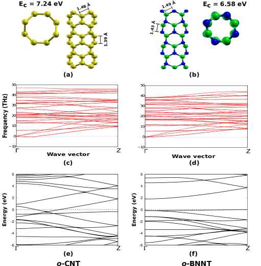
Stacking of units of o-MLs and structural buckling along z-direction can result in formation of nanotubes. Hence, synthesis of such nanotubes is possible in high pressure compression of o-MLs. Nanotubes of C (o-CNT) and BN (o-BNNT) thus formed, along with the values of Ec are shown in Figs. 8 (a) and (b). The phonon dispersion spectra of o-CNT and o-BNNT (Figs. 8 (c) and (d)) confirm the dynamical stability of these NTs. The diameters of o-CNT and o-BNNT are 3.6 Å and 3.57 Å respectively. It may be noted that the smallest radius reported for stable CNT (obtained by rolling of graphene) is greater than 2 - 4 Å. Qin et al. (2000) The bond lengths for o-NTs are not identical along zigzag and armchair directions. The bond lengths of o-CNT and o-BNNT along zigzag direction are 1.48 Å and 1.49 Å, while along armchair direction are 1.39 Å and 1.43 Å respectively. Interestingly, the average bond lengths of o-CNT and o-BNNT are 1.43 Å and 1.46 Å respectively, comparable to respective average bond lengths of h-MLs (1.43 Å and 1.45Å). If strains of +3.212 %, -3.212% and +3.928%, -1.426 % are applied for graphene and h-BN lattices and the sheets are rolled to form NTs, bond lengths along armchair and zigzag directions turn out to be comparable to respective o-NTs, as mentioned above. The calculated strain energies to deform the sheets (difference of total energy of strained and unstrained structure per atom) for h-MLs of C and BN are quite small viz., 0.05 eV/atom and 0.04 eV/atom respectively. However, rolling of sheet to form NTs is large as is discussed below. We have estimated the formation energies for these two processes. The formation energy is calculated as per atom difference in the energies of respective o-MLs and nanotubes and is a measure of energy required for stacking and buckling of o-MLs. On the other hand, in case of nanotubes formed by rolling h-ML, this formation energy corresponds to rolling of respective MLs to form nanotubes. For BNNT, the calculated formation energies per atom are 0.20 eV and 0.52 eV with respect to o-ML and h-ML of BN respectively. For CNT these values are 0.24 eV and 0.75 eV with respect to o-ML and h-ML of C respectively. Comparatively small values of formation energy for o-CNT and o-BNNT suggest strong possibility of experimental synthesis of such nanotubes by stacking and compressing respective o-MLs. Considering the calculated formation energy of rolling of respective strained h-MLs, it is obvious that a large amount of energy is to be supplied for rolling of respective h-MLs to form extremely small nanotubes. The o-NTs reported in this work can be considered as single strip thick zigzag nanotubes of h-MLs of C and BN. Hence, to obtain NTs of smaller radius, stacking of buckled o-MLs seems to be a plausible way.
Electronic structures of o-CNT and o-BNNT, incorporated in Figs. 8 (e) and (f) respectively, show that o-BNNT is semiconducting while o-CNT is semi-metallic. At such extremely small sizes, the band gap of 1.83 eV of o-BNNT is exciting for various applications. Respective charge density and Bader charge analysis show that bonding in o-BNNT is ionic in nature and is covalent in o-CNT. The site projected angular momentum decomposed density of states (refer supporting information) and patterns of charge transfer of o-CNT and o-BNNT match with the corresponding o-MLs. These extremely thin NTs are important for fundamental studies due to many factors such as confinement, ionic BNNT versus covalent CNT, large electric fields that they can generate, etc.
III.5 Conclusions
A class of tetragonally symmetric 2D o-ML family is proposed as the possible stable planar structures after h-ML family. Among large pool of investigated materials from group II-VI, III-V and IV elements, seven materials (BN, GaN, AlN, C, SiC, GeC, BP) (we have previously shown that o-ZnO is possible Gaikwad et al. (2017)) have shown possible stable structure of o-MLs. Six of these o-MLs belong to P4/mbm (127) and more symmetric o-C belongs to P4/mmm (123) tetragonal space group. Energetic, dynamic and thermal stability of these o-MLs along with the electronic structures and bonding are discussed. We propose that those o-MLs which show soft phonons can stabilize in the form of multilayer assemblies. Electronic structure of o-MLs show that hybrid p-states dominate near the Fermi level and resulting band gap varies from 4.13 eV to metallic nature. Most of the o-MLs have direct/quasi-direct band gap in visible/IR/UV region. o-MLs being comparatively less symmetric with large open volume are potential candidates for dielectric, hydrogen storage and optoelectronic applications. The doping and/or defect studies suggest substitutional doping of C8 rings in o-BN is favorable. Nearly equal lattice parameters of o-MLs of C and BN favor formation of hybrid assemblies. The structural stability, energetics and variation in electronic structure of hybrid assemblies are discussed.
Buckling and stacking of o-MLs leads to stable new bulk phases. Among few possibilities of buckling, the zigzag buckling between interlayers of o-C leads to bct-C8 or o-C phase of carbon (space group I4/mcm (140)) with 3.12 eV indirect band gap. The high band gap (4.78 eV) o-BN phase of boron nitride belongs to body centered tetragonal structure and I4cm (108) space group. Similar to BN, other reported binary o-ML materials also show stable o-bulk phase. The cleavage energy of o-MLs of o-C and o-BN from their respective bulk-phase are within experimentally realizable range.
Stable octagonal nanotubes namely o-CNT and o-BNNT are metallic and semiconducting (band gap 1.83 eV) respectively. Such NTs can be realized by stacking an octagonal ring on its mirror image or by cutting single column chunk of respective o-bulk. These NTs are limiting cases of plausible nanotube formation and can not be formed by rolling MLs.
This work demonstrates the significance of octagonal geometry, possibility of existence of octagonal structures and a need to understand the electronic structure of such systems. Moreover, octagonal and other haeckelite structured monolayers can be designed by assembling the geometries of passivated clusters obtained from ground state geometries of very small clusters. Additional computational efforts to understand the underlying science and experimental realization of these structures are warranted.
Acknowledgements.
Authors would like to acknowledge DST Nanomission Council, Government of India for financial support through a major research project (DST/NM/NS-15/2011(G)).References
- Novoselov et al. (2012) K. Novoselov, V. Falko, L. Colombo, P. Gellert, M. Schwab, and K. Kim, Nature 490, 192 (2012).
- Meunier et al. (2016) V. Meunier, A. G. Souza Filho, E. B. Barros, and M. S. Dresselhaus, Rev. Mod. Phys. 88, 025005 (2016).
- Pereira et al. (2009) V. M. Pereira, A. H. Castro Neto, and N. M. R. Peres, Phys. Rev. B 80, 045401 (2009).
- Naumis et al. (2017) G. G. Naumis, S. Barraza-Lopez, M. Oliva-Leyva, and H. Terrones, Rep. Prog. Phys. 80, 096501 (2017).
- Dean et al. (2013) C. Dean, L. Wang, P. Maher, C. Forsythe, F. Ghahari, Y. Gao, J. Katoch, M. Ishigami, P. Moon, M. Koshino, T. Taniguchi, K. Watanabe, K. Shepard, J. Hone, and P. Kim, Nature 497, 598 (2013).
- Liu et al. (2013) Z. Liu, L. Ma, G. Shi, W. Zhou, Y. Gong, S. Lei, X. Yang, J. Zhang, J. Yu, K. Hackenberg, A. Babakhani, J. Idrobo, R. Vajtai, J. Lou, and P. Ajayan, Nat. Nanotechnol. 8, 119 (2013).
- Diniz et al. (2017) G. Diniz, E. Vernek, and F. Souza, Physica. E Low. Dimens. Syst. Nanostruct. 85, 264 (2017).
- Ong and Reed (2012) M. Ong and E. Reed, ACS Nano 6, 1387 (2012).
- Levy et al. (2010) N. Levy, S. Burke, K. Meaker, M. Panlasigui, A. Zettl, F. Guinea, A. Castro Neto, and M. Crommie, Science 329, 544 (2010).
- Xiaomu et al. (2015) W. Xiaomu, T. He, X. Weiguang, S. Yi, M. Wen-Tian, A. Mohammad, X. Qian-Yi, Y. Yi, X. Jian-Bin, and R. Tian-Ling, NPG Asia Mater. 7, e154 (2015).
- Raja and Zhao (2019) A. Raja and X. Zhao, Nature Nanotechnology 14, 832 (2019).
- Wang and Wang (2019) W. Wang and T. Wang, Nature Nanotechnology 14, 819 (2019).
- De et al. (2011) S. De, A. Willand, M. Amsler, P. Pochet, L. Genovese, and S. Goedecker, Phys. Rev. Lett. 106, 225502 (2011).
- Gaikwad et al. (2017) P. Gaikwad, P. Pujari, S. Chakroborty, and A. Kshirsagar, J. Phys. : Cond. Matt. 29, 335501 (2017).
- Sahin et al. (2009) H. Sahin, S. Cahangirov, M. Topsakal, E. Bekaroglu, E. Akturk, R. T.Senger, and S. Ciraci, Phys. Rev. B 80, 155453 (2009).
- Zhang et al. (2015a) S. Zhang, J. Zhouc, Q. Wang, X. Chend, Y. Kawazoef, and P. Jena, PNAS 112, 2372 (2015a).
- Liu et al. (2012) Y. Liu, G. Wang, Q. Huang, L. Guo, and X. Chen, Phys. Rev. Lett. 108, 225505 (2012).
- Sheng et al. (2012) X. L. Sheng, H. J. Cui, F. Ye, Q. B. Yan, Q. R. Zheng, and G. Su, J. Appl. Phys. 112, 074315 (2012).
- Topsakal et al. (2009) M. Topsakal, S. Cahangirov, E. Bekaroglu, and S. Ciraci, Phys. Rev. B 80, 235119 (2009).
- Zhang et al. (2015b) Y. Zhang, J. Lee, W.-L. Wang, and D.-X. Yao, Comp. Mater. Sci. 110, 109 (2015b).
- Brown and Shuford (2016) P. A. Brown and K. Shuford, Nanoscale 8, 19287 (2016).
- Hohenberg and Kohn (1964) P. Hohenberg and W. Kohn, Phys. Rev. 136, B864 (1964).
- Kohn and Sham (1965) W. Kohn and L. J. Sham, Phys. Rev. 140, A1133 (1965).
- Kresse and Hafner (1993) G. Kresse and J. Hafner, Phys. Rev. B 47, 558 (1993).
- Kresse and Hafner (1994) G. Kresse and J. Hafner, Phys. Rev. B 49, 14251 (1994).
- Kresse and Furthmüller (1996a) G. Kresse and J. Furthmüller, Comp. Mat. Sci. 6, 15 (1996a).
- Kresse and Furthmüller (1996b) G. Kresse and J. Furthmüller, Phys. Rev. B 54, 11169 (1996b).
- Blöchl (1994) P. E. Blöchl, Phys. Rev. B 50, 17953 (1994).
- Perdew et al. (1996) J. P. Perdew, K. Burke, and M. Ernzerhof, Phys. Rev. Lett. 77, 3865 (1996).
- Perdew et al. (1997) J. P. Perdew, K. Burke, and M. Ernzerhof, Phys. Rev. Lett. 78, 1396 (1997).
- Togo and Tanaka (2015) A. Togo and I. Tanaka, Scr. Mater. 108, 1 (2015).
- Lee and Martin (1997) I. H. Lee and R. M. Martin, Phys. Rev. B 56, 7197 (1997).
- Narasimhan and de Gironcoli (2002) S. Narasimhan and S. de Gironcoli, Phys. Rev. B 65, 064302 (2002).
- Yan et al. (2008) J. A. Yan, W. Y. Ruan, and M. Y. Chou, Phys. Rev. B 77, 125401 (2008).
- Klemens (2001) P. G. Klemens, Int. J. Thermophys. 22, 265 (2001).
- Camacho-Mojica and López-Urías (2015) D. Camacho-Mojica and F. López-Urías, Scientific Reports 17902, 5 (2015).
- Umemoto et al. (2010) K. Umemoto, R. M. Wentzcovitch, S. Saito, and T. Miyake, Phys. Rev. Lett. 104, 125504 (2010).
- Shahrokhi et al. (2017) M. Shahrokhi, B. Mortazavi, and G. Berdiyorove, Solid state Commun. 253, 51 (2017).
- theoretical chemistry code forum (2011) U. theoretical chemistry code forum, “Asymmetric charges in graphene and bug in output,” (2011).
- Ci et al. (2010) L. Ci, L. Song, C. Jin, D. Jariwala, D. Wu, Y. Li, A. Srivastava, Z. F. Wang, K. Storr, L. Balicas, F. Liu, and P. M. Ajayan, Nature Mater. 9, 430 (2010).
- Yuge (2009) K. Yuge, Phys. Rev. B 79, 114109 (2009).
- Liu et al. (2008) P. Liu, H. Cui, and G. Yang, Cryst. Growth Des. 8, 581 (2008).
- Johnston and Hoffmann (1989) R. Johnston and R. Hoffmann, J. Am. Chem. Soc. 111, 810 (1989).
- Qin et al. (2000) L.-C. Qin, X. Zhao, K. Hirahara, Y. Miyamoto, Y. Ando, and S. Iijima, Nature 408, 50 (2000).