Phase-field modeling of \textgamma/\textgamma´´ microstructure formation in Ni-based superalloys with high \textgamma´´ volume fraction
Abstract
The excellent mechanical properties of the Ni-based superalloy IN718 mainly result from coherent \textgamma´´ precipitates. Due to a strongly anisotropic lattice misfit between the matrix and the precipitate phase, the particles exhibit pronounced plate-shaped morphologies. Using a phase-field model, we investigate various influencing factors that determine the equilibrium shapes of \textgamma´´ precipitates, minimizing the sum of the total elastic and interfacial energy. Upon increasing precipitate phase fractions, the model predicts increasingly stronger particle-particle interactions, leading to shapes with significantly increased aspect ratios. Matching the a priori unknown interfacial energy density to fit experimental \textgamma´´ shapes is sensitive to the phase content imposed in the underlying model. Considering vanishing phase content leads to lower estimates of the interfacial energy density, as compared to estimates based on realistic phase fractions of . We consider the periodic arrangement of precipitates in different hexagonal and rectangular superstructures, which result from distinct choices of point-symmetric and periodic boundary conditions. Further, non-volume conserving boundary conditions are implemented to compensate for strains due to an anisotropic lattice mismatch between the \textgamma matrix and the \textgamma´´ precipitate. As compared to conventional boundary conditions, this specifically tailored simulation configuration does not conflict with the systems periodicity and provides substantially more realistic total elastic energies at high precipitate volume fractions. The energetically most favorable superstructure is found to be a hexagonal precipitate arrangement.
© 2020. The manuscript is made available under the license CC-BY-NC-ND 4.0
![]()
I Introduction
Ni-based superalloys have various applications at elevated temperatures, especially in stationary gas turbines and airplane engines. The main strengthening mechanism, which makes these alloys applicable for high temperatures is particle strengthening by coherent precipitations (Paulonis et al., 1969). Apart from the most prominent case, the \textgamma´ strengthening of Ni-based superalloys for turbine blade materials, a series of alloys exist that are mainly strengthened by the tetragonal metastable \textgamma´´ phase. These Nb-containing alloys, such as the well-known IN718, can be cast, forged, machined and welded which renders them ideal candidates for industrial applications.
As IN718 contains up to of the cubic phase \textgamma´, several authors modified its composition in order to increase the volume fraction of \textgamma´´ phase and to get rid of \textgamma´ precipitates while maintaining the composition of the matrix (Kirman and Warrington, 1970; Kusabiraki et al., 1994, 1996, 1999). Table 1 shows the nominal composition of IN718 and a derivative IN718M without \textgamma´ forming elements. Recent studies aim at deliberate co-precipitation of \textgamma´ and \textgamma´´ to exploit ripening inhibiting effects (Detor et al., 2018; Shi et al., 2019) and a dual lattice microstructure (Mignanelli et al., 2017, 2018). IN718 powders also gain importance for additive manufacturing in the industrial environment (Amato et al., 2012; Yap et al., 2015; Strößner et al., 2015; Trosch et al., 2016). It was recently found that alloys containing only one orientational variant of \textgamma´´, a so-called single-variant microstructure, can be used to tailor creep resistant materials (Zhang et al., 2019).
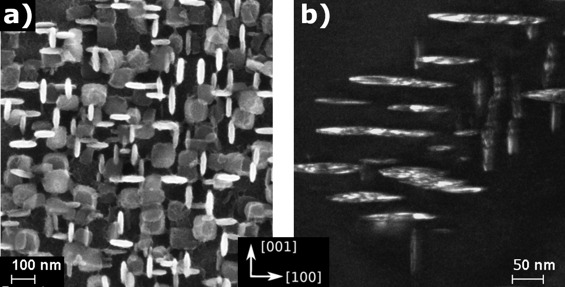
Figure 1a) shows a scanning electron microscope (SEM) image of a \textgamma/\textgamma´´ microstructure in IN718M after homogenization at for . The precipitates are found in the Nb-rich interdendritic region. Table 1 also shows the local composition measured by energy-dispersive x-ray spectroscopy. The precipitates are arranged regularly in three spatial orientations perpendicular to one another and show a plate-shaped morphology. The volumetric \textgamma´´ phase fraction is . Figure 1b) shows a dark-field transmission electron microscope (TEM) image of \textgamma´´ preciptates in IN718M.
| Composition in wt. % | Ni | Cr | Nb | Mo | Fe | Al | Ti |
|---|---|---|---|---|---|---|---|
| IN718 nominal max. | 55.0 | 21.0 | 5.5 | 3.3 | bal. | 0.8 | 1.2 |
| IN718 nominal min. | 50.0 | 17.0 | 4.8 | 2.8 | bal. | 0.2 | 0.7 |
| IN718M nominal | 58.0 | 18.0 | 5.0 | 3.0 | bal. | – | – |
| IN718M measured | 56.8 | 17.6 | 6.6 | 3.2 | 15.8 | – | – |
The shapes and spatial arrangements of coherent misfitting precipitates have been modeled assuming a single precipitate embedded in infinite matrix (Khachaturyan, 1967; Khachaturyan and Airapetyan, 1974; Johnson and Cahn, 1984; Voorhees et al., 1992; Thompson et al., 1994; Thompson and Voorhees, 1999; Li et al., 2004). The influence of elastic inhomogeneity (Schmidt and Gross, 1997) and periodic arrangements of precipitates with higher precipitate volume fractions (Mueller et al., 2000) on precipitate shapes were studied using the boundary integral method. Comparison of simulated precipitate shapes to experimentally observed microstructures can be used to obtain realistic values of the interfacial energy density (Lanteri et al., 1986; Devaux et al., 2008; Holzinger et al., 2019).
The phase-field method is widely considered to be a powerful tool for modeling solidification as well as solid-state phase transformations based on a diffuse description of the phase boundaries (Chen, 2002; Asta et al., 2009; Steinbach, 2009; Wang and Li, 2010; DeWitt and Thornton, 2018). Consistent phase-field modeling of precipitation bases on a thermodynamic functional, which is an integral over a local phenomenological potential energy density. This phenomenological energy density may take into account phase boundary energy, multi-component solute distribution and elastic strain caused by external loads or lattice misfit between the phases. By general variational principles, one can subsequently derive a consistent set of coupled partial differential equations that describes the kinetics of the microstructure evolution in the chosen configuration. The phase-field method is frequently used to study the temporal evolution of \textgamma/\textgamma´ microstructures (Wang et al., 1998; Zhu et al., 2004; Gaubert et al., 2010; Mushongera et al., 2015; Pang et al., 2015; Bhaskar, 2018) as well as \textgamma/\textgamma´´ systems (Zhou et al., 2014; Ji et al., 2016). The variational formulation of the phase-field method makes it a useful tool to determine equilibrium precipitate morphologies (Wang et al., 1991, 1993; Leo et al., 1998; Cottura et al., 2015; Jokisaari et al., 2017; Bhadak et al., 2018) and precipitate interactions (Degeiter et al., 2020). In the scope of this work, we develop a phase-field model to extensively evaluate factors influencing two-dimensional \textgamma´´ precipitate shapes. We consider anisotropic and phase-dependent elastic properties, a tetragonally anisotropic misfit, elastic particle interactions at high volume content as well as an isotropic energy density of the \textgamma/\textgamma´´ interface.
II The \textgamma/\textgamma´´ microstructure in Ni-based superalloys
The ordered phase \textgamma´´ has a body-centered tetragonal (bct) crystallographic structure and is of the stoichiometric type Ni3Nb. In an fcc matrix, it forms distinctive plate-shaped precipitates. The face-centered cubic (fcc) unit cell of the matrix phase \textgamma can be described by a single lattice parameter that is the distance between two atom sites along a direction. The bct unit cell of the \textgamma´´ phase can be made up by two fcc unit cells stacked on top of each other with the central atom site and the corner atom sites being Nb atoms. One can now distinguish two lattice parameters and , the latter being also referred to as the tetragonal axis. The plate normal of the precipitate is always parallel to the direction.
Coherent precipitation of \textgamma´´ in a \textgamma matrix is possible due to the relations
| (1) |
when
| (2) |
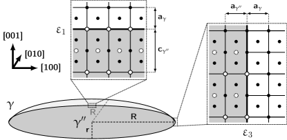
This means that there are three possible orientational variants in which the tetragonal phase can coherently precipitate (see Figure 1) (Slama and Abdellaoui, 2000). Note that Equation (1) states that there is a misfit of the lattice parameters that leads to strains when lattice coherency is kept. Two distinguishable misfit strains and in and direction, respectively, can be found.
Figure 2 shows a schematic drawing of a \textgamma´´ precipitate. The precipitate is depicted as an oblate spheroid with two major and a minor half axis and , respectively. The orientational relations given in Equation (2) are depicted at the interface. To experimentally quantify the shape of \textgamma´´ precipitates one usually takes the aspect ratio that is defined as the ratio or, for non-elliptical precipitates the ratio of the plate diameter to its thickness. Usually, \textgamma´´ precipitates exhibit major radii of less than and reportedly start to lose full coherency at major radii larger than (Cozar and Pineau, 1973; Slama et al., 1997; Devaux et al., 2008; Ji et al., 2016).
II.1 Elastic constants
General elastic behavior is described by the tensor of elasticity . In this work, we use the tensor of elasticity in Voigt notation . This is a reduction to a tensor that is not invariant under rotation. The cubic \textgamma and the tetragonal \textgamma´´ phase both exhibit anisotropic elastic properties due to their crystallographic symmetry. A set of three independent elastic constants is needed to describe cubic anisotropy (, , ) and six are needed for tetragonal anisotropy, respectively (, , , , , ). Isotropic elasticity is described by a set of two independent constants with .
In this work we use experimental data generated by resonance ultrasound spectroscopy (RUS) for polycrystal (isotropic) and single crystal (anisotropic) samples of IN718. We assume that matrix and precipitates in IN718 and IN718M have comparable elastic properties. For the \textgamma´´ phase data from a first-principles study was used (Connétable et al., 2011; Dai and Liu, 2010). This data is valid at , therefore, an estimate about temperature dependence has to be made. Due to the lack of experimental data, we propose to assume the same temperature dependence for all elastic constants considered, as it was already done by Moore et al. (Moore et al., 2016). In this work, we assume a linear temperature dependence of the elastic constants
| , | (3) |
where is the temperature, is an elastic constant at and is the coefficient of temperature dependence. To determine , experimental data for pure Nickel from to room temperature is used (Simmons, 1965; Luo et al., 2011). For higher temperatures, we assume the same temperature dependence as it was determined for a \textgamma´ single crystal (Ni-Al23-Ti1-Ta1) via RUS (Fleck et al., 2018). We find to be . Table 2 shows the extrapolated elastic constants of \textgamma´´ at . Elastic homogeneity is given when matrix and precipitate have the same tensor of elasticity ().
The elastic constants of a single crystal alloy composed of coherent phases can be estimated by a simple rule of mixture
| (4) |
where is an elastic constant of the alloy, is the elastic constant of phase and is the volume fraction of . Knowing the elastic properties for all but one phase and for the alloy itself, it is possible to estimate the tensor of elasticity for the remaining phase. In the case of \textgamma´´ precipitates in a cubic matrix, the three orientational variants appear statistically. The tensor of elasticity of such an alloy maintains cubic symmetry. To find the tensor of elasticity, with cubic symmetry, for a mixture of all three orientation variants of the \textgamma´´ phase, we apply the modified mixture rule
| (5) | ||||
| (6) | ||||
| (7) |
Having estimated the complete tensors of elasticity for the IN718M alloy and the \textgamma´´ phase, the anisotropic tensor of elasticity of the matrix can be calculated using Equation (4) and (7). In Table 2 also a stiffness contrast is given. In the case of anisotropic elasticity, we apply the mixture rule in Equation (7) to compare the respective tensors of elasticity. We report a mean value as the different elastic constants show different stiffness contrasts.
To evaluate the influence of inhomogeneous stiffness of the phases and of crystallographic anisotropy on the precipitate shapes, we use different sets of elastic constants. Phase-independent isotropic elastic properties leave only the anisotropic lattice misfit to determine the precipitate shape. Phase-wise isotropic data allows to observe the influence of elastic inhomogeneity. Individual cubic and tetragonally anisotropic phase data describes the elastic properties of the system in the most comprehensive way.
| elastic constants in GPa | contrast | |||||||
|---|---|---|---|---|---|---|---|---|
| isotropic | homogen.1 | (242) | 120 | 61 | ||||
| matrix3 | (240) | 120 | 60 | |||||
| \textgamma´´ phase4 | (250) | 120 | 65 | |||||
| anisotropic | homogen.1 | 205 | 145 | 90 | ||||
| matrix3 | 200 | 150 | 90 | |||||
| \textgamma´´ phase2 | 220 | 240 | 140 | 120 | 88 | 87 | ||
All evaluations of the elastic moduli of the phases based Equation (4) are dependent on the volume fraction . In this work, we assume a \textgamma´´ volume fraction of which is in accordance with previously reported values (Brooks and Bridges, 1988; Theska et al., 2018) and higher than it was calculated using the Thermo-Calc software with the TCNi8 database.
II.2 Anisotropic lattice misfit
Due to the two distinguishable lattice parameters and in \textgamma´´ and the strict orientation relation of the coherent interface in a \textgamma/\textgamma´´ microstructure the stress-free transformation strain exhibits a tetragonal symmetry. In Voigt notation, this misfit strain tensor of the \textgamma´´ phase is
| (9) |
with the two distinguishable dilatational misfit strains and . Those are calculated from the experimentally determined lattice parameters of the phases via
| (10) |
Note that in the denominator we find only the lattice parameter of the matrix. This is because we define the eigenstrain of the matrix to be zero. The lattice parameters of an IN718 matrix and of the \textgamma´´ precipitates were measured by Slama et al. (Slama et al., 1997; Slama and Abdellaoui, 2000) using X-ray diffractometry (XRD) for samples aged at 953 K and 1023 K after quenching. Lattice parameters were also measured using neutron diffraction (Lawitzki et al., 2019). Measured lattice parameters and corresponding misfit strains are given in Table 3. Other measurements of the lattice parameters in IN718 show similar misfits (Cozar and Pineau, 1973, 1973; Oblak et al., 1974; Chaturvedi and Han, 1983; Kusabiraki et al., 1996; Zhang et al., 2018). Note that the absolute value of is high compared to \textgamma´ precipitates ( (Völkl et al., 1998a)) but similar for both XRD and neutron diffraction. On the other hand, the values of differ strongly. The misfit ratio is one magnitude larger for neutron diffraction measurements than for the XRD measurements.
Both measurements, however, determined the in-situ constrained misfit that is the lattice misfit superimposed by elastic deformation of the material. A more suiting input parameter would be the unconstrained misfit that is the misfit calculated from lattice parameters of strain-free bulk samples of the phases. The unconstrained misfit can notably differ from the constrained misfit (Völkl et al., 1998b; Müller et al., 1993).
| lattice param. in pm | misfit in | ||||||
|---|---|---|---|---|---|---|---|
| source | |||||||
| (Slama et al., 1997; Slama and Abdellaoui, 2000) | 359.5 | 361.4 | 742.1 | 5.29 | 32.1 | 6.1 | |
| (Lawitzki et al., 2019) | 359.8 | 360.0 | 743.8 | 0.56 | 33.6 | 60.0 | |
III Phase-field Modeling of equilibrium precipitate shapes
The phase-field model for the simulation of solid-phase precipitation in multicomponent alloys is based on the following phenomenological potential functional (Plapp, 2011; Mushongera et al., 2015, 2015),
| (11) |
where denotes an abbreviation for the partial derivative with respect to the spacial directions , e.g. . The potential density splits into an interfacial, a bulk elastic contribution and a chemical contribution . The continuous fields describing the evolution of the system are the phase-field , which discriminates between the fcc matrix () and the ordered \textgamma´´ phase () as well as the elastic displacement field , which describes the local distortion of a material point by elastic deformations.
III.1 Interfacial contribution
The interfacial contribution to the potential functional is
| (12) |
where a summation over repeated indices is implied. The phase-field parameter determines the interface width and the parameter corresponds to the interfacial energy density. denotes a calibration factor for the interface energy density, which is calculated via the line integral, , where denotes the direction normal to the interface, and is a phase-field with just one full transition from to . Further, the equilibrium potential is
| (13) |
where the parameter couples to the discretization grid via the numerical grid spacing . This potential has two local minima at and , which correspond to the two distinct phases of the system. In the continuum limit , this potential converges to the usual quartic double-well potential , as .
Figure 3 shows the equilibrium potential for , which will be used throughout this work as well as for the continuum limit . The reason for choosing this potential is to diminish effects from the numerical grid in the phase-field model , according to the ideas around the so-called “Sharp phase-field method” as proposed by Finel et al. (Finel et al., 2018; Fleck et al., 2019).

In conjunction with the formulation of the interfacial contribution, we impose an interpolation function for any elastic and chemical energy density contribution: . This is the minimal polynomial satisfying the necessary interpolation conditions and and also having a vanishing slope at and , to not shift the bulk states in the presence of finite driving forces (Kassner et al., 2001; Fleck et al., 2010). The Allen Cahn-type phase-field evolution equation is
| (14) |
where is the interface mobility that is chosen as high as possible while still guaranteeing stability of the solver. All these equations are solved by finite difference schemes operating on one fixed square grid with an explicit Euler-type time integration.
III.2 Elastic contribution
The elastic contribution to the potential energy density is defined in terms of the phase-dependent elastic properties: the total strain field that is derived from the local displacements , the misfit strain of the precipitate phase, and the phase-dependent elastic constants (Fleck et al., 2018). Specifically the elastic energy density is written as
| (15) |
The phase dependent elastic constants as well as the eigenstrains are interpolated as
| (16) | ||||
| (17) |
where denotes the considered phase and denotes the local phase-field parameter. We interpolate on the level of the elastic parameters, not on the level of the bulk energies to minimize the amount of interfacial excess energy (Durga et al., 2013). A Lagrangian formulation in the small strain approximation is used. The local stress tensor is defined as the partial derivative of the elastic energy density Equation (15) with respect to the strain tensor,
| (18) |
The solution for the elastic displacement field is given by the condition of mechanic equilibrium
| (19) |
In summary, the model requires to solve the full set of coupled partial differential equations of second order, as given by Equation (14) for the phase-field and Equation (19) for the elastic displacements. With regard to the mechanical equilibrium, that is assumed at every time step of the phase-field solver, we perform a Jacobi relaxation.
III.3 Chemical contribution
Realistic microstructure exhibit conserved phase volumes, due to the conservation of mass (Fleck et al., 2018). Here, the preserved phase volume is achieved by the chemical contribution to the potential energy density
| (20) |
which contains an extra time-dependent and homogeneous driving force contribution , such that a volume change of the precipitate phase is prohibited (Fleck et al., 2011). A more sophisticated description of the kinetics of diffusion-limited precipitation, which explicitly involves the chemical diffusion of multiple alloying elements, is also possible (Mushongera et al., 2015; Fleck et al., 2018), but beyond the scope of the present work.
The phase fraction is conserved when
| (21) |
Inserting the right-hand side of phase-field Equation (14) into (21), we obtain the time-dependent homogeneous driving force
| (22) |
where the following abbreviations are introduced:
| (23) | ||||
| (24) |
This method for achieving preserved phase volumes can also be applied to configurations involving more than two phases (Nestler et al., 2008).
III.4 Boundary conditions
All simulations are carried out in rectangular two-dimensional domains. Elastic interactions between neighboring precipitates can be adjusted by changing the domain size with respect to the size of the initial precipitate. For both cubic and tetragonal symmetry, it is sufficient to model one quarter of the particle with respective mirror boundary conditions. Therefore, for every considered spatial dimension exists one mirror boundary and one opposing domain boundary that ensures periodicity (henceforth referred to as the periodic boundary). The phase-field is imposed with no-flux boundary conditions in both cases.
For the elastic displacement fields, standard boundary conditions such as periodic conditions, strain-free conditions or stress-free boundary conditions are not useful. Here, a distinction is required due to the following reasons. If simple stress-free condition are imposed the state of deformation turns non-uniform, and the boundary looses its flatness, which conflicts with the periodicity of the system. Periodic or strain-free conditions conserve periodicity, but do not allow for the misfitting precipitate to change the volume of the simulation domain and/or its aspect ratio, leading to unrealistically high total deformation energies.
Therefore, at the mirror boundaries vanishing normal displacements and vanishing shear strains are imposed, where denotes the elastic displacement field, and denote the direction normal and tangential to the boundary, respectively. At the opposing periodic boundary again vanishing shear strain conditions are imposed. But for the normal displacement, we homogeneously impose , where denotes the average value of all normal displacements at the boundary. Homogeneous normal displacements are required to avoid conflicts with the periodicity of the systems and to not introduce strain artifacts. The average overall normal displacements at the boundary is used to allow for the volume change, which leads to more realistic total deformation energies. This boundary condition has previously been applied to finite-element modeling of misfit stresses (Glatzel and Feller-Kniepmeier, 1989; Probst-Hein et al., 1999; Preußner et al., 2005; Pollock and Argon, 1988) and equilibrium shapes (Mueller et al., 2000) in the \textgamma/\textgamma´ system. Due to these boundary conditions, all opposing domain boundaries stay parallel yet no spurious elastic energy is introduced through artificial volume conservation.
Figure 4a) shows a simulation domain with an aspect ratio of and the imposed boundary conditions for the displacements normal to the boundaries. Modeling a precipitate in a periodic configuration implies an arrangement of the precipitates in a strict long-range order. Specifically, the above boundary conditions imply a superstructure in which the precipitates are arranged in the corners of a cuboidal unit-cell (Mueller et al., 2000) with the distance to each nearest neighbor being twice the domain side lengths. Henceforth this configuration will be referred to as a rectangular superstructure.
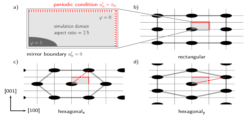
By application of antisymmetric variation boundary conditions at one periodic boundary, one can change the arrangement superstructure (Gurevich et al., 2010). Therefore the tangential strains and the phase-field must be imposed with a point-symmetric operation with respect to a bisecting point of the respective domain boundary. Figure 4b) shows the rectangular superstructure and Figure 4c) and d) show two hexagonal arrangements henceforth referred to as hexagonalx and hexagonaly. The respective bisecting point that is used for the antisymmetry operation is indicated as a red dot. Antisymmetric boundary conditions applied to more than one boundary lead to virtual simulation domains that include more than one precipitate. This state is not represented by the actual simulation domain and renders non-physical solutions.
IV Simulation results and discussion
To determine the shape of coherent \textgamma´´ precipitates we set up phase-field simulations considering the interfacial energy and elastic contributions with constant \textgamma´´ phase fraction. Beginning from an arbitrary precipitate shape the phase-field converges towards the minimum of the total energy. The lower left edge of the domain lies in the precipitates center point with the domain boundaries being parallel to the crystallographic and directions. The observed phase fraction in two dimensions appears higher than the respective three-dimensional phase fraction. Beginning from the discussed initial simulation configuration the system was relaxed for a minimum of iterations. Subsequently the aspect ratio and the total energy contributions were evaluated.
To describe the ratio between interfacial and elastic contribution to the pattern formation we introduce a dimensionless parameter similar to the one presented in (Voorhees et al., 1992) as
| (25) |
where is the elastic energy density scale with the shear modulus of the homogeneous isotropic elastic data provided in Table 2 and the largest misfit strain from Table 3 to make it independent of the misfit ratio . is the isotropic interfacial energy density. The length scale of a particle is defined as and will be used to normalize lengths. denotes the major half axes and the minor half axis of the precipitate, as shown in Figure 2.
IV.1 Variation of anisotropic misfit and elastic constants
To evaluate the influence of the anisotropy of the misfit strains given in Table 3, the simulation domain was chosen to be gridpoints with one quarter of an initial, spherical particle with a gridpoint radius in the bottom left corner. The low phase content together with homogeneous and isotropic elastic material data leaves only the misfit ratio and the interfacial energy density to determine the equilibrium shape. In this configuration the tetragonal symmetry of the misfit strain is the cause of the plate shape of the \textgamma´´ precipitates. There is significant uncertainty about the absolute values of the lattice misfit strain (see Table 3). The misfit strain is fixed to a value of and is varied to examine the influence of the anisotropy of the misfit on the precipitate shape.
Figure 5a) shows the precipitate aspect ratio as determined by the phase-field model as a function of the misfit ratio . At the precipitates are circular with an aspect ratio of . With rising misfit ratio the precipitates show elliptical shapes with an aspect ratio that rises until a plateau is reached. In the plateau region, changes in the misfit ratio do no longer influence the precipitate shape. For all considered values of the plateau is reached at . The misfit data considered in Table 3 lies between and and thus lies inside the plateau region.

In Figure 5a) the simulations are compared to an analytical model for the optimum shape of \textgamma´´ precipitates. The shape is assumed to be a rotational ellipse with an aspect ratio . The elastic energy density is homogeneous inside the precipitate and can be calculated using Eshelby’s solution to the inclusion problem (Eshelby, 1957) as
| (26) |
where and the parameters only depend on the aspect ratio of the ellipsoid (Cozar and Pineau, 1973; Devaux et al., 2008). The optimum aspect ratio is then the aspect ratio that minimizes the sum of elastic energy and interface energy as follows
| (27) |
with and being the surface and volume of an oblate rotational ellipse with major radius and aspect ratio (Cozar and Pineau, 1973). The aspect ratios determined by the phase-field model and by the analytical model are very close and the analytic model shows the same plateau for large misfit ratios.
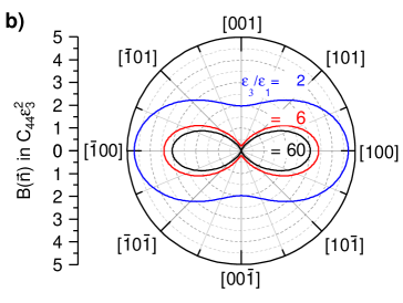
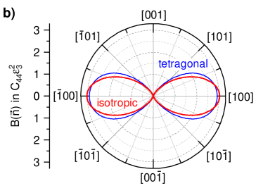
Figure 5b) shows the orientation dependent elastic relaxation function that quantifies soft and hard crystallographic directions independent of the precipitate shape (Khachaturyan, 1967; Morris Jr, 2010; Degeiter et al., 2020). It is defined as
| (31) |
with implied summation over repeated indices. The elastic properties are assumed to be homogeneous and isotropic (see Table 2) and only is varied. For the direction minimizing has been found to be the tetragonal axis () (Wen et al., 1981). Assuming vanishing interfacial energy density the equilibrium precipitate shape is an infinitely extended plate with a () habit plane (Wen et al., 1981; Morris Jr, 2010). Finite interfacial energy contributes significantly to the formation of the experimentally observed shapes by counteracting this strong anisotropy driving force of that is observed for and . For the precipitate aspect ratio is influenced only by and the contribution of is therefore negligible. In Figure 5b), for the anisotropy of is significantly less pronounced and less interfacial energy density is required to counteract to that anisotropy to reach a comparable aspect ratio as shown in Figure 5a).
The two analytical approaches to the tetragonal inclusion problem discussed above both show, qualitatively and quantitatively, that for the formation of plate-shaped precipitates is only driven by . As indicated by the gray area in Figure 5a), the large uncertainty range of the misfit strain ratio for the \textgamma´´ phase fully lies within this limit!
Figure 6 shows the aspect ratio of the precipitates as a function of for a realistic misfit ratio . The aspect ratios of the plate-shaped precipitates increase with increasing as the elastic bulk energy of the system dominates the interfacial part. The precipitate shapes were found to be ellipses with aspect ratios close to the prediction of Equation (26) and (27). The good agreement between the two-dimensional phase-field model and the three-dimensional analytical model in Figure 5a) and 6 suggests that a two-dimensional model is sufficient to describe the aspect ratio of a \textgamma´´ precipitate.
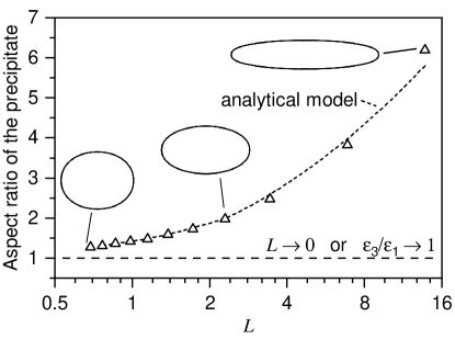
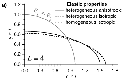
Figure 7a) shows the influence of inhomogeneous elastic properties for precipitate and matrix phase on the precipitate shape as well as the influence of anisotropy of the elastic constants (see Table 2). The simulation configuration is the same as in Figure 5a) with and . For reference, the circular shape of a precipitate with an isotropic misfit () and isotropic homogeneous elasticity is given. In the considered case inhomogeneous elastic properties do not influence the precipitate shapes significantly. Anisotropic elastic properties lead to an elliptical precipitate with a reduced aspect ratio.
Figure 7b) shows the elastic energy density (see Equation (31)) for isotropic and tetragonally anisotropic elastic constants (see Table 2) and . The tetragonal anisotropy of the \textgamma´´ phase leads to the direction being elastically softer than in the isotropic case. For tilted directions orientations changes non-uniformly. The ratio of does not change significantly compared to the ratio with . This qualitative change in the energetics of tilted interfaces leads to the observed shortening of the precipitate when anisotropy of the elastic properties is considered.
We conclude that without elastic interaction the formation of plate-shaped \textgamma´´ precipitate shapes is mainly driven by the tetragonally anisotropic misfit in the system. The aspect ratio of the precipitates depends on the misfit strains and on the interfacial energy density. For realistically high misfit ratios no influence of the absolute value of on the precipitate shape is found. Inhomogeneity of the elastic constants has negligible influence on the precipitate shapes. Anisotropic elastic properties lead to elliptical precipitates with decreased aspect ratios.
IV.2 Precipitate superstructure and particle-particle interaction
A square simulation domain at realistically high phase contents eventually leads to precipitates coagulating. Rectangular simulation domains have to be set up to avoid that. The aspect ratio of the rectangular simulation domains will be discussed as part of the simulation configuration. In the following simulations elastic data of the phases is anisotropic, and (see Table 2 and 3). We describe the interaction between neighboring precipitates by the particle distance. It is defined as the distance between the centers of the precipitates in or - direction or two times the height of the simulation domain.
Figure 8 shows the results of a simulation study in a domain with a fixed aspect ratio of and rectangular superstructure. The size of the initial elliptical precipitate was kept constant ( and gridpoints) and the relative size of the simulation domain was varied in order to model different particle distances. The aspect ratio of a particle increases by in a system when the particle distance is reduced from to . Note that due to the conserved aspect ratio of the domain also the particle distance in -direction is reduced simultaneously and the phase fraction is rising. Interestingly, the increase in the aspect ratio at high phase contents does not lead to a simple stretching of the particle but also to a deviation from the elliptical shape. The precipitate shape has reduced curvature along its major extent. Similar elastic interactions affecting the precipitate shape have been reported for \textgamma/\textgamma´ with volume fractions up to (Mueller et al., 2000). Distant precipitates experience attraction and close precipitates are repulsed leading to an equilibrium matrix channel width between the precipitates (Su and Voorhees, 1996a, b; Goerler et al., 2017; Jokisaari et al., 2017).
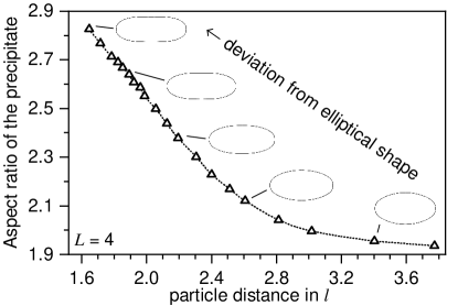
Figure 9 shows precipitate shapes influenced by elastic particle-particle interaction in different superstructures at a particle distance of . The determined precipitate shapes subject to different implicit superstructures illustrate the significant influence of long-range order on precipitate shapes. The area of all three shapes is equal. The shapes for rectangular and hexagonaly arrangement can be approximated with ellipses. The superstructure hexagonaly shortens the precipitate by but it remains an ellipse. The hexagonalx arrangement leads to deviation from the elliptical shape visible due to the fact that the phase boundary of the precipitate “rectangular” is intersected twice by the phase boundary of “hexagonalx”. The sites of the intersections are indicated by arrows.

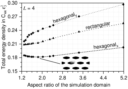
Figure 10 shows the total energy density plotted against the domain aspect ratio for the three possible superstructures at a particle distance of . The hexagonalx arrangement is the energetically most favorable. The rectangular arrangement is intermediate and the hexagonaly superstructure shows the highest energy density. The rectangular and the hexagonaly superstructure both exhibit a steadily dropping energy density for aspect ratios of the simulation domain close to 1. It is only in the energetically most favorable hexagonalx arrangement that one finds a distinct minimum at an aspect ratio of the simulation domain of . The implied microstructure of such an energetically optimum configuration is also given in Figure 10. For spherical precipitates with an isotropic misfit a cubic arrangement was found to be the energetic optimum (Khachaturyan and Airapetyan, 1974).
The configuration that was found to be the energetically most favorable is the one where precipitates exhibit the largest distance to their nearest neighbors in the direction of the highest misfit strain . An effect of the high elastic energy contribution in the hexagonaly arrangement is visible in Figure 9, where it leads to additional shortening of the precipitate. Being the energetically minimum configuration of the presented model a hexagonalx superstructure with a domain aspect ratio of will be used to describe a realistic single-variant \textgamma/\textgamma´´ microstructure with a realistic volume fraction.
IV.3 Energy density of the \textgamma/\textgamma´´ interface
To reproduce experimentally observed aspect ratios of \textgamma´´ precipitates, we set up a simulation study assuming constant misfit strains and isotropic interfacial energy density. The simulation domain has an aspect ratio of , the initial particle has a radius of gridpoints and a hexagonalx superstructure was used. The sizes of the respective simulation domains were set such that they resemble a realistic \textgamma´´ volume fraction of . We approximate the volume fraction as the ratio between the volume of a spheroid with the same aspect ratio as the two-dimensional shape and the volume of a respective three-dimensional simulation domain by exploiting the system’s four-fold rotational symmetry around the tetragonal axis. The approximated volume content is then given by
| (32) |
where is the aspect ratio of the precipitate and is the particle distance normalized by . As shown in Figure 9 the precipitate shapes deviate from the elliptical shape and therefore assuming a spheroidal precipitate as in Equation (32) is not accurate. We assume that this inaccuracy is negligible as the inaccuracy of the volume content measurement itself is comparably large. Note that the single-variant microstructure discussed in this work reflects material aged under load for several hours (Gao et al., 1996; Zhou et al., 2014) or specifically tailored material (Zhang et al., 2019). We assume that particle interactions of perpendicularly oriented precipitates lead to the same stretching of the precipitates but might impose further constraint to the growth of precipitates that is not reflected by the proposed model.
Figure 11a) shows experimental data from various sources reporting the aspect ratio of \textgamma´´ precipitates as a function of the precipitate major radius (Han et al., 1982; Sundararaman et al., 1992; Slama et al., 1997; Devaux et al., 2008). Interfacial dislocations occur when full coherency of precipitates larger than is lost (Cozar and Pineau, 1973; Slama et al., 1997; Devaux et al., 2008). Here, we restrict to fully coherent precipitates, as interfacial dislocations alter the strain field around a precipitate (Ji et al., 2016) in a way that is not reflected by the model. The aspect ratio of the precipitates increase with increasing precipitate size due to the rising importance of elastic bulk effects over the interfacial energy with (see Equation (25)). In simulations with a particle distance of an interfacial energy density of to is necessary to reproduce experimentally observed aspect ratios. This is in good accordance with the previously reported isotropic \textgamma/\textgamma´´ interfacial energy density of (Devaux et al., 2008). This value was obtained by the application of an analytical model for the equilibrium aspect ratio of a \textgamma´´ precipitate given in Equation (26) and (27) based on Eshelby’s inclusion theory (Eshelby, 1957; Cozar and Pineau, 1973). This model assumes isotropic and homogeneous elasticity, isotropic interfacial energy density, a spheroidal precipitate shape and no elastic interaction. The prediction of this model for the size dependent aspect ratio of a precipitate with an interfacial energy density of is also shown in Figure 11a). An interfacial energy density of was found for precipitates in a Fe-Ni-Ta alloy (Cozar and Pineau, 1973).
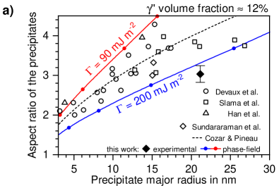
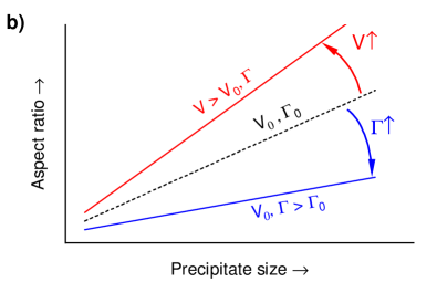
Figure 11a) shows that at a realistic volume fraction of the isotropic energy density needed to reproduce experimental findings lies between and , which corresponds to . In a real system the interfacial energy of a tetragonal to cubic interface might be strongly anisotropic (Vaithyanathan et al., 2004; Kim et al., 2017), which could also be included in a phase-field model. As to the best of our knowledge, no information about the magnitude of such an anisotropy for the coherent \textgamma/\textgamma´´-interface is available, we assume an isotropic . The obtained isotropic interfacial energy densities are a factor of higher than those determined without consideration of elastic particle-particle interaction. Figure 11a) includes data from averaged aspect ratios generated from TEM images as for example given in Figure 1b). 72 fully coherent \textgamma´´ precipitates in IN718M were evaluated by image analysis. The samples were homogenized at for and subsequently water quenched. The error bar shows the standard deviation of the aspect ratio. For this system, we predict an isotropic interfacial energy density of .
Figure 11b) illustrates the influence of the competing factors discussed above on the aspect ratio of a precipitate. A higher the interfacial energy density provides a tendency towards more spherical precipitates, i.e. smaller aspect ratios. Stronger elastic interactions between precipitates at higher volume fraction , in turn, lead to higher precipitate aspect ratios (see Figure 11a). To estimate the interfacial energy density from the experimentally observed aspect ratios of precipitates it is crucial to take into account the elastic interactions of precipitates at finite volume fractions.
Comparison of theoretically determined equilibrium shapes with experimentally observed shapes is a possible way to get information about the interfacial energy (Lanteri et al., 1986; Devaux et al., 2008; Holzinger et al., 2019). However, the accuracy of this method is limited by the underlying model description of the equilibrium shape and by the possibility to experimentally observe precipitates in their equilibrium. The model presented in this work is in many ways an improvement over existing analytical models as it takes into account elastic interactions between precipitates in an two-dimensional optimum, non-rectangular arrangement and tetragonal/cubic anisotropy of the elastic constants for both phases. It is limited by being only a realistic description of a uniform single-variant microstructure that does not take into account the kinetics of precipitate growth that might have strong influence on the shapes of experimentally observed precipitates (Vaithyanathan et al., 2002). It was also found that a periodic arrangement of precipitates must not always be a stable configuration (Degeiter et al., 2020).
V Conclusion
We evaluate influencing factors on equilibrium shapes of \textgamma´´ precipitates in Ni-based superalloys considering one orientational variant. The shapes are determined using a phase-field formulation taking into account interfacial and elastic energy contributions.
-
1.
At negligible elastic particle-particle interaction, the phase-field model provides elliptic equilibrium shapes \textgamma´´ that are fully consistent with former analytic descriptions (Eshelby, 1957; Cozar and Pineau, 1973). The aspect ratio of a precipitate increases with increasing misfit strain . The precipitate shape is influenced by only for . Inhomogeneity and anisotropy of the elastic constants have less significant influence on the \textgamma´´ precipitate shape.
-
2.
Elastic particle-particle interactions significantly influence precipitate shapes at realistically high volume fractions. Different periodic arrangements of \textgamma´´ precipitates are modeled by respectively tailored boundary conditions. A decreased particle distance leads to an increased precipitate aspect ratio.
-
3.
Non-volume conserving displacement boundary conditions allow precise determination of the total energy density of periodic precipitation microstructures. The energetically most favorable superstructure is a hexagonalx precipitate arrangement (see Figure 4c).
-
4.
The evaluation of interfacial energy density based on equilibrium shapes is sensitive to the phase content. At a realistic volume fraction of , an interfacial energy density between and leads to precipitate aspect ratios that match experimental observations. Respective interfacial energy densities determined without accounting for elastic interaction between the precipitates are lower.
CRediT authorship contribution statement
F. Schleifer: Conceptualization, Methodology, Software, Validation, Formal Analysis, Investigation, Writing – Original Draft, Visualization. M. Holzinger: Conceptualization, Methodology, Software. Y.-Y. Lin: Conceptualization, Investigation, Data Curation, Validation. U. Glatzel: Supervision, Resources, Writing – Review & Editing, Project Administration, Funding Acquisition. M. Fleck: Conceptualization, Software, Supervision, Writing – Review & Editing, Project Administration, Funding Acquisition.
Declaration of Competing Interest
Authors have no conflict of interest to declare.
Acknowledgements
This work is funded by the Deutsche Forschungsgemeinschaft (DFG) in the priority program SPP 1713 (GL181/53-1|FL826/3-1). We thank the Federal Ministry of Education and Research (BMBF) for the financial support under the running project ParaPhase (funding code: 01IH15005B). The financial support of the Federal Ministry for Economics and Energy (BMWi) of the Federal Republic of Germany under the running project COORETEC: ISar (funding code: 03ET7047D) is greatly acknowledged. We thank our former colleague F. Krieg for the provision of RUS data and A. Finel from ONERA in Châtillon, France for the discussion on tetragonal anisotropy.
References
- Paulonis et al. (1969) D. F. Paulonis, J. M. Oblak, D. S. Duvall, Precipitation in Nickel-base Alloy 718., Amer. Soc. Metals, Trans. Quart. 62 (1969) 611–622.
- Kirman and Warrington (1970) I. Kirman, D. H. Warrington, The Precipitation of Ni3Nb Phases in a Ni-Fe-Cr-Nb Alloy, Metallurgical Transactions 1 (1970) 2667–2675.
- Kusabiraki et al. (1994) K. Kusabiraki, I. Hayakawa, S. Ikeuchi, T. Ooka, Morphology of " precipitates in Ni-18Cr-16Fe-5Nb-3Mo Alloy, Iron and Steel (1994) 348–352.
- Kusabiraki et al. (1996) K. Kusabiraki, I. Hayakawa, S. Keuchi, T. Ooka, Lattice Constants of and " Phases and "/ Lattice Mismatches in a Ni-15Cr-8-Fe-6Nb Alloy, ISIJ 36 (1996) 310–316.
- Kusabiraki et al. (1999) K. Kusabiraki, T. Tsutsumi, S. Saji, Effects of cold rolling and annealing on the structure of " precipitates in a Ni-18Cr-16Fe-5Nb-3Mo alloy, Metallurgical and Materials Transactions A 30 (1999) 1923–1931.
- Detor et al. (2018) A. J. Detor, R. DiDomizio, R. Sharghi-Moshtaghin, N. Zhou, R. Shi, Y. Wang, D. P. McAllister, M. J. Mills, Enabling Large Superalloy Parts Using Compact Coprecipitation of and ", Metallurgical and Materials Transactions A 49 (2018) 708–717.
- Shi et al. (2019) R. Shi, D. P. McAllister, N. Zhou, A. J. Detor, R. DiDomizio, M. J. Mills, Y. Wang, Growth behavior of /" coprecipitates in Ni-Base superalloys, Acta Materialia 164 (2019) 220–236.
- Mignanelli et al. (2017) P. M. Mignanelli, N. G. Jones, E. J. Pickering, O. M. Messé, C. M. Rae, M. C. Hardy, H. J. Stone, Gamma-gamma prime-gamma double prime dual-superlattice superalloys, Scripta Materialia 136 (2017) 136–140.
- Mignanelli et al. (2018) P. M. Mignanelli, N. G. Jones, M. C. Hardy, H. J. Stone, On the Time-Temperature-Transformation Behavior of a New Dual-Superlattice Nickel-Based Superalloy, Metallurgical and Materials Transactions A 49 (2018) 699–707.
- Amato et al. (2012) K. N. Amato, S. M. Gaytan, L. E. Murr, E. Martinez, P. W. Shindo, J. Hernandez, S. Collins, F. Medina, Microstructures and mechanical behavior of Inconel 718 fabricated by selective laser melting, Acta Materialia 60 (2012) 2229–2239.
- Yap et al. (2015) C. Y. Yap, C. K. Chua, Z. L. Dong, Z. H. Liu, D. Q. Zhang, L. E. Loh, S. L. Sing, Review of selective laser melting: Materials and applications, Applied Physics Reviews 2 (2015) 041101.
- Strößner et al. (2015) J. Strößner, M. Terock, U. Glatzel, Mechanical and Microstructural Investigation of Nickel-Based Superalloy IN718 Manufactured by Selective Laser Melting (SLM), Advanced Engineering Materials 17 (2015) 1099–1105.
- Trosch et al. (2016) T. Trosch, J. Strößner, R. Völkl, U. Glatzel, Microstructure and mechanical properties of selective laser melted Inconel 718 compared to forging and casting, Materials Letters 164 (2016) 428–431.
- Zhang et al. (2019) H. Zhang, C. Li, Q. Guo, Z. Ma, H. Li, Y. Liu, Improving creep resistance of nickel-based superalloy Inconel 718 by tailoring gamma double prime variants, Scripta Materialia 164 (2019) 66–70.
- Khachaturyan (1967) A. Khachaturyan, Some questions concerning the theory of phase transformations in solids, Soviet Phys. Solid State 8 (1967) 2163–2168.
- Khachaturyan and Airapetyan (1974) A. Khachaturyan, V. Airapetyan, Spatially periodic distributions of new phase inclusions caused by elastic distortions, Physica status solidi (a) 26 (1974) 61–70.
- Johnson and Cahn (1984) W. C. Johnson, J. W. Cahn, Elastically Induced Shape Bifurcations, Acta Metallurgica 32 (1984) 1925–1933.
- Voorhees et al. (1992) P. W. Voorhees, G. B. McFadden, W. C. Johnson, On the morphological development of second-phase particles in elastically-stressed solids, Acta Metallurgica Et Materialia 40 (1992) 2979–2992.
- Thompson et al. (1994) M. E. Thompson, C. S. Su, P. W. Voorhees, The equilibrium shape of a misfitting precipitate, Acta Metallurgica Et Materialia 42 (1994) 2107–2122.
- Thompson and Voorhees (1999) M. E. Thompson, P. W. Voorhees, Equilibrium particle morphologies in elastically stressed coherent solids, Acta Materialia 47 (1999) 983–996.
- Li et al. (2004) X. Li, K. Thornton, Q. Nie, P. W. Voorhees, J. S. Lowengrub, Two- and three-dimensional equilibrium morphology of a misfitting particle and the Gibbs-Thomson effect, Acta Materialia 52 (2004) 5829–5843.
- Schmidt and Gross (1997) I. Schmidt, D. Gross, The equilibrium shape of an elastically inhomogeneous inclusion, Journal of the Mechanics and Physics of Solids 45 (1997) 1521–1549.
- Mueller et al. (2000) R. Mueller, S. Eckert, D. Gross, 3D equilibrium shapes of periodically arranged anisotropic precipitates with elastic misfit, Archives of Mechanics 52 (2000) 663–683.
- Lanteri et al. (1986) V. Lanteri, T. Mitchell, A. H. Heuer, Morphology of tetragonal precipitates in partially stabilized ZrO2, Journal of the American Ceramic Society 69 (1986) 564–569.
- Devaux et al. (2008) A. Devaux, L. Nazé, R. Molins, A. Pineau, A. Organista, J. Y. Guédou, J. F. Uginet, P. Héritier, Gamma double prime precipitation kinetic in Alloy 718, Materials Science and Engineering: A 486 (2008) 117–122.
- Holzinger et al. (2019) M. Holzinger, F. Schleifer, U. Glatzel, M. Fleck, Phase-field modeling of -precipitate shapes in nickel-base superalloys and their classification by moment invariants, European Physical Journal B 92 (2019).
- Chen (2002) L.-Q. Chen, Phase field models for microstructure evolution, Annual Review of Materials Research 32 (2002) 113–140.
- Asta et al. (2009) M. Asta, C. Beckermann, A. Karma, W. Kurz, R. Napolitano, M. Plapp, G. Purdy, M. Rappaz, R. Trivedi, Solidification microstructures and solid-state parallels: Recent developments, future directions, Acta Materialia 57 (2009) 941.
- Steinbach (2009) I. Steinbach, Phase-field models in materials science, Modelling Simul. Mater. Sci. Eng. 17 (2009) 73001.
- Wang and Li (2010) Y. Wang, J. Li, Phase field modeling of defects and deformation, Acta Materialia 58 (2010) 1212.
- DeWitt and Thornton (2018) S. DeWitt, K. Thornton, Phase field modeling of microstructural evolution, in: Computational Materials System Design, Springer, 2018, pp. 67–87.
- Wang et al. (1998) Y. Wang, D. Banerjee, C. Su, A. Khachaturyan, Field kinetic model and computer simulation of precipitation of L12 ordered intermetallics from fcc solid solution, Acta Materialia 46 (1998) 2983–3001.
- Zhu et al. (2004) J. Zhu, T. Wang, A. Ardell, S. Zhou, Z. Liu, L. Chen, Three-dimensional phase-field simulations of coarsening kinetics of particles in binary Ni-Al alloys, Acta Materialia 52 (2004) 2837–2845.
- Gaubert et al. (2010) A. Gaubert, Y. Le Bouar, A. Finel, Coupling phase field and viscoplasticity to study rafting in Ni-based superalloys, Philosophical Magazine 90 (2010) 375.
- Mushongera et al. (2015) L. T. Mushongera, M. Fleck, J. Kundin, Y. Wang, H. Emmerich, Effect of Re on directional -coarsening in commercial single crystal Ni-base superalloys: A phase field study, Acta Materialia 93 (2015) 60–72.
- Pang et al. (2015) Y. Pang, Y. S. Li, X. Wu, W. Liu, Z. Hou, Phase-field simulation of diffusion-controlled coarsening kinetics of phase in Ni-Al alloy, International Journal of Materials Research 106 (2015) 108–113.
- Bhaskar (2018) M. S. Bhaskar, Quantitative phase field modelling of precipitate coarsening in Ni-Al-Mo alloys, Computational Materials Science 146 (2018) 102–111.
- Zhou et al. (2014) N. Zhou, D. C. Lv, H. L. Zhang, D. McAllister, F. Zhang, M. J. Mills, Y. Wang, Computer simulation of phase transformation and plastic deformation in IN718 superalloy: Microstructural evolution during precipitation, Acta Materialia 65 (2014) 270.
- Ji et al. (2016) Y. Ji, Y. Lou, M. Qu, J. D. Rowatt, F. Zhang, T. W. Simpson, L.-Q. Chen, Predicting Coherency Loss of " Precipitates in IN718 Superalloy, Metallurgical and Materials Transaction A 47 (2016) 3235.
- Wang et al. (1991) Y. Wang, L.-Q. Chen, A. Khachaturyan, Shape evolution of a precipitate during strain-induced coarsening: a computer simulation, Scripta Metallurgica et Materialia 25 (1991) 1387–1392.
- Wang et al. (1993) Y. Wang, L.-Q. Chen, A. Khachaturyan, Kinetics of strain-induced morphological transformation in cubic alloys with a miscibility gap, Acta Metallurgica et Materialia 41 (1993) 279–296.
- Leo et al. (1998) P. H. Leo, J. S. Lowengrub, H.-J. Jou, A diffuse interface model for microstructural evolution in elastically stressed solids, Acta Materialia 46 (1998) 2113–2130.
- Cottura et al. (2015) M. Cottura, Y. Le Bouar, B. Appolaire, A. Finel, Rôle of elastic inhomogeneity in the development of cuboidal microstructures in Ni-based superalloys, Acta Materialia 94 (2015) 15–25.
- Jokisaari et al. (2017) A. M. Jokisaari, S. S. Naghavi, C. Wolverton, P. W. Voorhees, O. G. Heinonen, Predicting the morphologies of precipitates in cobalt-based superalloys, Acta Materialia 141 (2017) 273–284.
- Bhadak et al. (2018) B. Bhadak, R. Sankarasubramanian, A. Choudhury, Phase-Field Modeling of Equilibrium Precipitate Shapes Under the Influence of Coherency Stresses, Metallurgical and Materials Transactions A 49 (2018) 5705–5726.
- Degeiter et al. (2020) M. Degeiter, Y. Le Bouar, B. Appolaire, M. Perrut, A. Finel, Instabilities in the periodic arrangement of elastically interacting precipitates in nickel-base superalloys, Acta Materialia 187 (2020) 41–50.
- Slama and Abdellaoui (2000) C. Slama, M. Abdellaoui, Structural characterization of the aged Inconel 718, Alloys and Compounds 306 (2000) 277–284.
- Cozar and Pineau (1973) R. Cozar, A. Pineau, Influence of coherency strains on precipitate shape in a FeNiTa alloy, Scripta Metallurgica 7 (1973) 851–854.
- Slama et al. (1997) C. Slama, C. Servant, G. Cizeron, Aging of the Inconel 718 alloy between 500 and 750 ∘C, Journal of Materials Research 12 (1997) 2298–2316.
- Connétable et al. (2011) D. Connétable, M. Mathon, J. Lacaze, First principle energies of binary and ternary phases of the Fe-Nb-Ni-Cr system, Calphad: Computer Coupling of Phase Diagrams and Thermochemistry 35 (2011) 588–593.
- Dai and Liu (2010) S. Dai, W. Liu, First-principles study on the structural, mechanical and electronic properties of and " phases in Inconel 718, Computational Materials Science 49 (2010) 414–418.
- Moore et al. (2016) I. J. Moore, M. G. Burke, E. J. Palmiere, Modelling the nucleation, growth and coarsening kinetics of " (D022) precipitates in the Ni-base Alloy 625, Acta Materialia 119 (2016) 157–166.
- Simmons (1965) G. Simmons, Single Crystal Elastic Constants and Calculated Aggregate Properties, Southern Methodist University, Dallas, Texas, 1965.
- Luo et al. (2011) F. Luo, X.-R. Chen, L.-C. Cai, Q. Wu, Thermoelastic properties of nickel from molecular dynamic simulations, Journal of Atomic and Molecular Science 2 (2011) 10–19.
- Fleck et al. (2018) M. Fleck, F. Schleifer, M. Holzinger, U. Glatzel, Phase-Field Modeling of Precipitation Growth and Ripening During Industrial Heat Treatments in Ni-Base Superalloys, Metallurgical and Materials Transactions A 49 (2018) 4146–4157.
- Brooks and Bridges (1988) J. W. Brooks, P. J. Bridges, Metallurgical stability of INCONEL alloy 718, in: Superalloys, TMS, 1988, pp. 33–42.
- Theska et al. (2018) F. Theska, A. Stanojevic, B. Oberwinkler, S. P. Ringer, S. Primig, On conventional versus direct ageing of Alloy 718, Acta Materialia 156 (2018) 116–124.
- Lawitzki et al. (2019) R. Lawitzki, S. Hassan, L. Karge, J. Wagner, D. Wang, J. von Kobylinski, C. Krempaszky, M. Hofmann, R. Gilles, G. Schmitz, Differentiation of - and "- precipitates in Inconel 718 by a complementary study with small-angle neutron scattering and analytical microscopy, Acta Materialia 163 (2019) 28–39.
- Cozar and Pineau (1973) R. Cozar, A. Pineau, Morphology of and " precipitates and thermal stability of Inconel 718 type alloys, Metallurgical Transactions 4 (1973) 47–59.
- Oblak et al. (1974) J. M. Oblak, D. F. Paulonis, D. S. Duvall, Coherency Strenghtening in Ni Base Alloys Hardened by D022 " Precipitate, Metall. Trans. 5 (1974) 143.
- Chaturvedi and Han (1983) M. C. Chaturvedi, Y.-F. Han, Strengthening mechanism in Inconel 718 superalloy, Metal Science 17 (1983) 145–149.
- Zhang et al. (2018) R. Y. Zhang, Z. N. Bi, H. L. Qin, J. Zhang, A. D. Fortes, Constrained Lattice Misfit Measurement in Bulk Inconel 718 Using High Resolution Neutron Diffraction, in: Proceedings of the 9th International Symposium on Superalloy 718 & Derivatives: Energy, Aerospace, and Industrial Applications, 2018, pp. 439–448.
- Völkl et al. (1998a) R. Völkl, U. Glatzel, M. Feller-Kniepmeier, Measurement of the lattice misfit in the single crystal nickel based superalloys CMSX-4, SRR99 and SC16 by convergent beam electron diffraction, Acta Materialia 46 (1998a) 4395–4404.
- Völkl et al. (1998b) R. Völkl, U. Glatzel, M. Feller-Kniepmeier, Measurement of the Unconstrained Misfit in the Nickel-Base Superalloy CMSX-4 with CBED, Scripta Materialia 38 (1998b) 893–900.
- Müller et al. (1993) L. Müller, U. Glatzel, M. Feller-Kniepmeier, Calculation of the internal stresses and strains in the microstructure of a single crystal nickel-base superalloy during creep, Acta Metallurgica et Materialia 41 (1993) 3401–3411.
- Plapp (2011) M. Plapp, Unified derivation of phase-field models for alloy solidification from a grand-potential functional, Physical Review E 84 (2011) 31601.
- Mushongera et al. (2015) L. T. Mushongera, M. Fleck, J. Kundin, F. Querfurth, H. Emmerich, Phase-field study of anisotropic -coarsening kinetics in Ni-base superalloys with varying Re and Ru contents, Advanced Engineering Materials 17 (2015) 1149.
- Finel et al. (2018) A. Finel, Y. Le Bouar, B. Dabas, B. Appolaire, Y. Yamada, T. Mohri, Sharp Phase Field Method, Physical Review Letters 121 (2018) 25501.
- Fleck et al. (2019) M. Fleck, F. Schleifer, U. Glatzel, Frictionless motion of marginally resolved diffuse interfaces in phase-field modeling, arXiv preprint arXiv:1910.05180 (2019).
- Kassner et al. (2001) K. Kassner, C. Misbah, J. Müller, J. Kappey, P. Kohlert, Phase-field modeling of stress-induced instabilities, Physical Review E 63 (2001) 36117.
- Fleck et al. (2010) M. Fleck, E. A. Brener, R. Spatschek, B. Eidel, Elastic and plastic effects on solid-state transformations: A phase field study, International Journal of Materials Research 101 (2010) 462–466.
- Durga et al. (2013) A. Durga, P. Wollants, N. Moelans, Evaluation of interfacial excess contributions in different phase-field models for elastically inhomogeneous systems, Modell. Sim. Mater. Sci. Eng. 21 (2013) 55018.
- Fleck et al. (2011) M. Fleck, L. Mushongera, D. Pilipenko, K. Ankit, H. Emmerich, On phase-field modeling with a highly anisotropic interfacial energy, Eur. Phys. J. Plus 126 (2011) 95.
- Nestler et al. (2008) B. Nestler, F. Wendler, M. Selzer, B. Stinner, H. Garcke, Phase-field model for multiphase systems with preserved volume fractions, Physical Review E 78 (2008) 11604.
- Glatzel and Feller-Kniepmeier (1989) U. Glatzel, M. Feller-Kniepmeier, Calculations of internal stresses in the / microstructure of a nickel-base superalloy with high volume fraction of -phase, Scripta Metallurgica 23 (1989) 1839–1844.
- Probst-Hein et al. (1999) M. Probst-Hein, A. Dlouhy, G. Eggeler, Interface dislocations in superalloy single crystals, Acta Materialia 47 (1999) 2497–2510.
- Preußner et al. (2005) J. Preußner, Y. Rudnik, R. Völkl, U. Glatzel, Finite-element modelling of anisotropic single-crystal superalloy creep deformation based on dislocation densities of individual slip systems, Zeitschrift für Metallkunde 96 (2005) 595–601.
- Pollock and Argon (1988) T. Pollock, A. Argon, Intermediate Temperature Creep Deformation in CMSX-3 Single Crystals, in: Superalloys, 1988, pp. 285–294.
- Gurevich et al. (2010) S. Gurevich, A. Karma, M. Plapp, R. Trivedi, Phase-field study of three-dimensional steady-state growth shapes in directional solidification, Physical Reviews E 81 (2010) 11603.
- Eshelby (1957) J. D. Eshelby, The determination of the elastic field of an ellipsoidal inclusion and related problems, Proceedings of the Royal Society of London. Series A. Mathematical and Physical Sciences 241 (1957) 376–396.
- Morris Jr (2010) J. Morris Jr, The Khachaturyan theory of elastic inclusions: Recollections and results, Philosophical Magazine 90 (2010) 3–35.
- Wen et al. (1981) S. Wen, E. Kostlan, M. Hong, A. Khachaturyan, J. Morris Jr, The preferred habit of a tetragonal inclusion in a cubix matrix, Acta Metallurgica 29 (1981) 1247–1254.
- Su and Voorhees (1996a) C. H. Su, P. W. Voorhees, The Dynamics of Precipitate Evolution in Elastically Stressed Solids - I. Inverse Coarsening, Acta Metallurgica 44 (1996a) 2001–2016.
- Su and Voorhees (1996b) C. H. Su, P. W. Voorhees, The Dynamics of Precipitate Evolution in Elastically Stressed Solids - II. Particle Alignement, Acta Metallurgica 44 (1996b) 1987–1999.
- Goerler et al. (2017) J. V. Goerler, I. Lopez-Galilea, M. L. Roncery, O. Shchyglo, W. Theisen, I. Steinbach, Topological phase inversion after long-term thermal exposure of nickel-base superalloys: Experiment and phase-field simulation, Acta Materialia 124 (2017) 151–158.
- Gao et al. (1996) M. Gao, S. Chen, D. Gary Harlow, R. P. Wei, Preferential coarsening of " precipitates in INCONEL 718 during creep, Metallurgical and Materials Transactions A 27 (1996) 3391–3398.
- Han et al. (1982) Y.-F. Han, P. Deb, M. C. Chaturvedi, Coarsening behaviour of "- and -particles in Inconel alloy 718, Metal Science 16 (1982) 555–562.
- Sundararaman et al. (1992) M. Sundararaman, P. Mukhopadhyay, S. Banerjee, Some aspects of the precipitation of metastable intermetallic phases in INCONEL 718, Metallurgical Transactions 23 A (1992) 2015–2028.
- Vaithyanathan et al. (2004) V. Vaithyanathan, C. Wolverton, L. Chen, Multiscale modeling of precipitation in Al-Cu binary alloys, Acta Materialia 52 (2004) 2973–2987.
- Kim et al. (2017) K. Kim, A. Roy, M. Gururajan, C. Wolverton, P. W. Voorhees, First-principles/Phase-field modeling of precipitation in Al-Cu alloys, Acta Materialia 140 (2017) 344–354.
- Vaithyanathan et al. (2002) V. Vaithyanathan, C. Wolverton, L. Chen, Multiscale modeling of precipitate microstructure evolution, Physical Review Letters 88 (2002) 125503.