Polarization loss in reflecting coating
Abstract
In laser gravitational waves detectors optical loss restricts sensitivity. We discuss polarization scattering as one more possible mechanism of optical losses. Circulated inside interferometer light is polarized and after reflection its plane of polarization can turn a little due to reflecting coating of mirror can have slightly different refraction index along axes in plane of mirror surface (optical anisotropy). This anisotropy can be produced during manufacture of coating (elasto-optic effect). This orthogonal polarized light, enhanced in cavity, produces polarization optical loss. Polarization map of mirrors is very important and we propose to measure it. Polarization loss can be important in different precision optical experiments based on usage of polarized light, for example, in quantum speed meter.
I Introduction
The advanced LIGO detectors directly detected gravitational waves (GW) B. P. Abbott et al (2016); B. P. Abbott et al, (2016) (LIGO Scientific Collaboration and Virgo Collaboration); B.P. Abbott et al, (2017a) (LIGO Scientific Collaboration and Virgo Collaboration); B.P. Abbott et al, (2017b) (LIGO Scientific Collaboration and Virgo Collaboration) and opened the era of gravitational wave astronomy. This detection became possible due to technology breakthroughs allowing to measure very small displacements of m of test masses LVC-Collaboration (2013); Dooley et al. (2014); Aasi et al. (2015); Abadie and et. al (2015); F. Acernese et al, (2015) (Virgo Collaboration); Grote (2010) separated by distance 4 km. The main limitation for the detector sensitivity in most sensitive frequency band from Hz to Hz V. B. Braginsky, Yu. Levin and S. P. Vyatchanin (1999); V.B.Braginsky, M.L.Gorodetsky and S.P.Vyatchanin (1999); V.B.Braginsky, M.L.Gorodetsky, S.P.Vyatchanin (2000); Harry et al. (in press) is produced by the thermal noise of the test masses. Currently, a main source for thermal noise is Brownian structural noise Nawrodt et al. (2011) in mirror coatings. Random stresses, thermally induced in the substrates and the coatings of the test masses, originate random deformations of their surfaces, which are detected at the interferometer output as thermal noise.
Optical losses of mirror — one more noise, restricting sensitivity of GW detectors. Optical losses prevents achievement of Standard Quantum Limit V.B. Braginsky (1968) and deteriorates optical squeezing H.J.Kimble, Yu.Levin, A.B.Matsko, K.S.Thorne and S.P.Vyatchanin (2001); Miao et al. (2019); Evans et al. (2013). Optical losses are mainly originated by scattering on roughness of mirror surface and imperfections of layers in interferometric coatings. In Advanced LIGO round trip losses in cavities in arms are about 100 ppm, in GW detectors of third generation these losses are planed to be lees, about 60 ppm GWIC 3G Committee (2019).
In this article we discuss one more possible mechanism of optical losses — polarization scattering produced by elasto-optic effect in reflecting coating. (Note, polarization scattering in substrates is also important, in particular it was analyzed in Krüger et al. (2015), however, it is not a subject of this paper.) In GW detectors the light, circulated inside interferometer, is polarized. In ideal case after reflection from mirror polarization of reflected light is conserved. However, reflecting coating can have slightly different refraction index along axes in plane of mirror surface. In other words elasto-optic effect can produces optical anisotropy of coating. This anisotropy can be produced during manufacture of coating. Then polarization of reflected light will be slightly turned. This small orthogonal polarized light, enhanced in cavity, produces polarization optical losses.
II Rough estimates of elasto-optic effect
The interferometric coating is evaporated on end (or input) mirrors. The temperature of coating during evaporation is about , so at room temperature K the coating will be stressed. Its deformation can be estimated as
| (1) |
where are thermal expansion coefficients of coating and substrate, here we put .
In ideal case the coating film is stressed uniformly, i.e. each element of coating is stressed equally in all direction and deformation is the same in all directions. It means that in this ideal case refraction index is the same for any deformations, i.e.
| (2) |
where are refraction indexes in coating for light polarized along axes on mirror surface. The axes are chosen so that () has maximal (minimal) value.
However, non-uniform heating during evaporation can create anisotropy in stressed coating. Then at room temperature the coating should consists of pieces in which deformation has different value and direction. One can estimate deformation in such piece through variation of temperature of coating during manufacture
| (3) |
Birefringence induces phase shift between ordinary and extraordinary waves:
| (4) |
Here we assume that (it corresponds to two quarter wavelength layers of coating), gives the estimate of relative power redistributed from the main to orthogonally polarized mode.
This estimate is rather large. Indeed, estimate (4) shows that after reflection about ppm of incident light will re-emitted in orthogonal polarization.
We can not point the possible size of isotropically stressed domains of coating — it is a subject of further experiment. We have two possibilities: large and small domains.
For large domains the sizes of anisotropic stressed domains are comparable with radius of light beam spot. In this case the main part of orthogonally polarized light will be emitted into main optical mode cavity. Hence, it will be resonantly enhanced and in light reflected from FP cavity the part of orthogonally polarized light will be enlarged. Indeed, its amplitude is equal to:
| (5) |
Here is power transmittance of input mirror of FP cavity (we assume perfect reflectivity of end mirror), is an amplitude of incident light. We see that is larger than (estimate based on (4)) by resonance factor . Then relative losses into orthogonally polarised light can be estimated as
| (6) |
Here we use estimate (4) and put .
Obviously, possibility of large domains existence is very low.
For another case of small domains the sizes of anisotropic stressed domains are much less than radius of light beam spot. In this case the main part of polarised light will be emitted quasi-isotropically into space. It means that estimate of ‘‘polarised’’ losses in this case can be estimated as . However its small part will be re-emitted in main mode and will be resonantly enhanced. Hence in this case the ‘‘polarized’’ losses have two part: quasi-isotropic and resonantly enhanced :
| (7) |
The coefficient can be calculated from map of difference refraction index . Obviously, fraction can be larger than unity.
The case of small domains looks more probable. Then the key problem is to measure birefringence map of coating of each mirror.
III Model
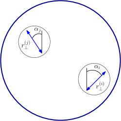
The diameter of mirrors in Advanced LIGO GW detectors are about 40 cm, the diameters of mirrors in GW detectors of third generation will be larger. We assume that small physical pieces of mirror coating have different values and directions of stresses, producing small birefringence as shown on Fig. 1. This birefringence can be detected by reflection of polarized light focused on small square on coating. The polarization of reflected light will slightly differ from polarization of incident light having small component of orthogonal polarization. In general case its amplitude is equal to
| (8) |
Here ‘‘orthogonal’’ amplitude reflection coefficient of -th piece (with square ) on coating surface, is angle between direction of incident light polarization and stress direction (birefringence axis) — see also Fig. 1. Obviously, small orthogonal polarization reaches maximum at optimal angle .
In general case one can assume that birefringence parameters of coating are function of coordinates on mirror surface: . They are different for each mirror and can be considered as random variable
Let incident light is vertically polarized and has Gaussian distribution in cross section (main mode), its electrical field is equal to:
| (9) | ||||
| (10) |
where is an amplitude of electrical field , is effective radius of light beam on mirror, integration is taken over mirror surface. Then amplitude of reflected orthogonal polarized light, emitted into main mode of cavity, is equal to
| (11) |
The average value ( are random value) and it is variation that should characterize relative orthogonal polarization component:
| (12) | ||||
| (13) |
Hence, we can estimate value of orthogonal polarized amplitude
| (14) |
Underline that mirror is a part of Fabry-Perot cavity, hence, the light emitted into main mode wave with amplitude will be resonantly enhanced. It is easy to show that in resonance case amplitudes of wave inside cavity and outside cavity are equal to:
| (15) |
Here are power reflectivity and transmittance of input mirror, . End mirror is assumed to be perfectly reflective. Pay attention that in (14) is mean amplitude inside cavity, amplitude of wave outside cavity is
| (16) |
and ratio of orthogonal polarized amplitude to mean amplitude outside cavity is equal to
| (17) |
where is cavity relaxation time, is round trip time. Even for ppm and we estimate
| (18) |
We see that Fabry-Perot cavity considerably enhances polarization loss (and noise) in main mode.
Discussion and Conclusion
In experiments with polarized light the appearance of light of orthogonal polarization means additional loss which can be called as polarization loss. For account of this polarization loss measurement of the polarization map is very important.
Note that in accordance of Fluctuation-Dissipation Theorem any losses produces additional noise, and hence, decreases experimental sensitivity.
Polarization loss (and noise) can be important for laser interferometric GW detectors because it means additional noise produced by light of orthogonal polarization in dark port. Another example, in order to surpass Standard Quantum Limit in GW detectors there were proposed the quantum speed meter based on polarization schemes S.L.Danilishin, F.Ya.Khalili (2012); Danilishin et al. (2019), and it is polarization noise which will restrict sensitivity of this speed meter.
For mirrors of laser interferometric GW detectors the roughness of surfaces are very important and measurement of roughness maps are performed now. We would like to pay attention that polarization map of these mirrors has not smaller importance and should be also performed.
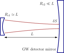
Polarization map measurement is not a simple task and in order to increase accuracy through resonant enhancement we propose to use cavity scheme shown on Fig. 2. Cavity is assembled by large mirror of GW detector and small additional mirror which curvature radius is about distance of cavity. Mirrors of GW detector have large curvature radius about several kilometers, so . Hence, it is approximately hemispherical cavity which waist is practically placed on the surface of GW detector mirror and can have size comparable with wave length . Rotating polarization of pump one can measure values and of spot (placed in waist of beam). Scanning light beam over surface of GW detector mirror one can measure polarization map.
Obviously, pump laser must have stable polarization. Also, small additional mirror has to have no polarization scattering or, at least, it should be known with high accuracy.
Note that polarization scattering in mirror substrate (silicon Krüger et al. (2015) in Einstein Telescope or Cosmic Explorer or sapphire in KAGRA) can also be important reason of additional losses and it should be carefully investigated.
Summing up, polarization loss (and noise) can be important in precision optical experiment and it should be investigated.
Acknowledgements.
Author acknowledges partial support from the Russian Foundation for Basic Research (Grant No. 19-29-11003) and from the TAPIR GIFT MSU Support of the California Institute of Technology. This document has LIGO number LIGO-P2000038.References
- B. P. Abbott et al (2016) B. P. Abbott et al (LIGO and Virgo Scientific Collaboration), Phys. Rev. Lett. 116, 061102 (2016).
- B. P. Abbott et al, (2016) (LIGO Scientific Collaboration and Virgo Collaboration) B. P. Abbott et al, (LIGO Scientific Collaboration and Virgo Collaboration), Phys. Rev. Lett. 116, 241103 (2016).
- B.P. Abbott et al, (2017a) (LIGO Scientific Collaboration and Virgo Collaboration) B.P. Abbott et al, (LIGO Scientific Collaboration and Virgo Collaboration), Phys. Rev. Lett. 119, 161101 (2017a).
- B.P. Abbott et al, (2017b) (LIGO Scientific Collaboration and Virgo Collaboration) B.P. Abbott et al, (LIGO Scientific Collaboration and Virgo Collaboration), Phys. Rev. Lett. 119, 141101 (2017b).
- LVC-Collaboration (2013) LVC-Collaboration, arXiv 1304.0670 (2013).
- Dooley et al. (2014) K. Dooley, T. Akutsu, S. Dwyer, and P. Puppo, arXiv 1411.6068 (2014).
- Aasi et al. (2015) J. Aasi, B. Abbott, et al., Classical and Quantum Gravity 32, 074001 (2015).
- Abadie and et. al (2015) J. Abadie and et. al, Classical and Quantum Gravity 32, 074001 (2015), eprint arXiv: 1411.4547.
- F. Acernese et al, (2015) (Virgo Collaboration) F. Acernese et al, (Virgo Collaboration), Classiacal and Quantum Gravity 32, 024001 (2015).
- Grote (2010) H. Grote, Classical and Quantum Gravity 27, 084003 (2010), ISSN 0264-9381, URL http://stacks.iop.org/0264-9381/27/i=8/a=084003?key=crossref.971d16e926625babd609e1cb2d1d8882.
- V. B. Braginsky, Yu. Levin and S. P. Vyatchanin (1999) V. B. Braginsky, Yu. Levin and S. P. Vyatchanin, Meas. Sci. Technol. 10, 589–606 (1999).
- V.B.Braginsky, M.L.Gorodetsky and S.P.Vyatchanin (1999) V.B.Braginsky, M.L.Gorodetsky and S.P.Vyatchanin, Physics Letters A 264, 1–10 (1999).
- V.B.Braginsky, M.L.Gorodetsky, S.P.Vyatchanin (2000) V.B.Braginsky, M.L.Gorodetsky, S.P.Vyatchanin, Physics Letters A 271, 303–307 (2000).
- Harry et al. (in press) G. Harry, T. Bodiya, and R. Desalvo, eds., Optical Coatings for Precision Measurement (Cambridge University Press, in press).
- Nawrodt et al. (2011) R. Nawrodt, S. Rowan, J. Hough, M. Punturo, F. Ricci, and J. Y. Vinet, Gen. Relativ. Gravit. 43, 593–622 (2011).
- V.B. Braginsky (1968) V.B. Braginsky, Sov. Phys. JETP 26, 831–834 (1968).
- H.J.Kimble, Yu.Levin, A.B.Matsko, K.S.Thorne and S.P.Vyatchanin (2001) H.J.Kimble, Yu.Levin, A.B.Matsko, K.S.Thorne and S.P.Vyatchanin, Physical Review D 65, 022002 (2001).
- Miao et al. (2019) H. Miao, N. Smith, and M. Evan, Physical Review X 9, 011053 (2019).
- Evans et al. (2013) M. Evans, L. Barsotti, P. Kwee, J. Harms, and H. Miao, Physical Review D 88, 022002 (2013).
- GWIC 3G Committee (2019) t. GWIC 3G Committee, R&D for the next generation of ground-based gravitational - wave detectors (2019), URL https://gwic.ligo.org/3Gsubcomm/documents/GWIC_3G_R_D_Subcommittee_report_July_2019.pdf.
- Krüger et al. (2015) C. Krüger, D. Heinert, A. Khalaidovski, J. Steinlechner, R. Nawrodt, R. Schnabel, and H. Lück, arXiv 1504.06503 (2015).
- S.L.Danilishin, F.Ya.Khalili (2012) S.L.Danilishin, F.Ya.Khalili, Living Reviews in Relativity 15, 5 (2012), URL http://http://relativity.livingreviews.org/Articles/lrr-2012-5.
- Danilishin et al. (2019) S. Danilishin, F. Khalili, and H. Miao, Living Reviews in Relativity 22, 2 (2019).