Microtomography on the ANATOMIX beamline at Synchrotron SOLEIL
Abstract
The ANATOMIX beamline at Synchrotron SOLEIL, operational since 2018, is dedicated to hard X-ray full-field tomography techniques. Operating in a range of photon energies from approximately 5 to 50 keV, it offers both parallel-beam projection microtomography, in absorption and phase contrast, and nanotomography using a zone-plate transmission X-ray microscope. With these methods, the beamline covers a range of spatial resolution from 20 nm to 20 µm, expressed in terms of useful pixel size. The variable beam size of up to 40 mm allows users to image large objects. Here we describe the microtomography instrumentation of the beamline.
1 Introduction
The French synchrotron light source SOLEIL has recently built a long undulator beamline named ANATOMIX (Advanced Nanotomographic Imaging with Coherent X Rays) for X-ray microtomography and nanotomography. ANATOMIX completes the imaging methods available at SOLEIL by full-field tomography at lower photon energies and smaller length scales than PSICHÉ [1], the other SOLEIL beamline offering full-field tomography as a main experimental method. The general layout and beam conditioning optics scheme have been reported elsewhere [2]. Here we report on the main features of the experimental stations, in particular for microtomography, and on the current state of the instrument. The nanotomography station is described in more detail in a separate article in this volume [3].
In its two experiment hutches located, respectively, at distances of 170 and 200 m from the source, ANATOMIX can take the white X-ray beam or a monochromatic beam from a double-crystal Si-111 monochromator (DCM) or (once fully completed) from a double-multilayer monochromator. The nanotomography facility is exclusively operated with the DCM. For microtomography, the beam at sample position without any X-ray optics is approximately 20 mm wide and 15 mm high. It can be widened to more than 40 mm by a horizontally focusing double mirror located 35 m from the source. The first of the two mirror substrates is concave and its radius can be varied with a bending mechanism. When the mirror is not needed, it can be retracted from the beam. Beryllium refractive lenses in the optics hutches can be used to collimate the beam and increase the flux density at the sample position. Table 1 lists the main parameters of the beamline and its end stations.
| \brExperimental methods | Microtomography (MT) in parallel-beam projection geometry |
|---|---|
| Nanotomography with a transmission X-ray microscope (TXM) | |
| Local tomography available (MT, TXM) | |
| Extended field (=“half acquisition”, “off-axis”) available (MT, TXM) | |
| Contrast modes | Absorption contrast (MT, TXM) |
| Inline phase contrast (MT); Zernike phase contrast (TXM) | |
| X-ray source | In-vacuum, cryogenically cooled U18 undulator |
| Spectral beam modes | Filtered white beam |
| Double-crystal monochromator Si-111 Bragg, vertical deflection | |
| Double-multilayer monochromator, vertical deflection(a) | |
| Geometrical beam | Double-bounce horizontally-reflecting mirror, removable, with bender |
| conditioning | Refractive lenses, removable |
| Photon energies available | 10 to 50 keV (white-beam microtomography) |
| 10 to 25 keV (monochromatic microtomography) | |
| 7 to 17 keV (TXM nanotomography) | |
| Beam size at sample | 40 15 mm2 (max.) |
| (horizontal vertical) | 20 15 mm2 (without optics) |
| Min. effective pixel size | 20 nm (TXM nanotomography) |
| 130 nm (microtomography) | |
| Digital cameras | Make and modelNo. of pixelsPixel sizeSpeed |
| Hamamatsu Orca Flash 4.0 V2204820486.5 µm100 fps | |
| pco.dimax HS42000200011 µm2277 fps | |
| pco.4000400826729 µm5 fps | |
| Hamamatsu Orca Lightning(b)460825925.5 µm30 fps | |
| Detector optics | Revolver-type optics (white or monochromatic beam): 5, 7.5, 10, 20 |
| and magnifications | High-resolution optics (monochromatic beam only): 10, 20 |
| Large-field optics (white or monochromatic beam): 0.48, 1, 2.1 | |
| Max. scan speed | 1 tomography scan per second (standard rotation stage) |
| 20 tomography scans per second (fast stage) | |
| \br (a)Foreseen. (b)Under commissioning. | |
2 Microtomography instrument layout and performance
Two almost identical microtomographs are available, one in each of the two experimental hutches; they mainly differ by the available range of propagation distances between sample and detector, which is limited to 2.1 m in the first hutch, whereas in the second hutch distances up to 6 m can be realized. In principle it is also possible to place a sample on the microtomograph in hutch 1 and use a detector in hutch 2, which can increase the propagation distance up to 37 m. Hutch 1 also contains the TXM. While it is not possible to conduct two experiments simultaneously, the microtomograph in hutch 2 can be used to install and test complex setups while other experiments are running in hutch 1. Detector optics developed at SOLEIL [5] (see also Table 1) give access to effective pixel sizes between 0.3 and about 20 µm in microtomography; these are complemented by the TXM with useful pixel sizes down to 20 nm.
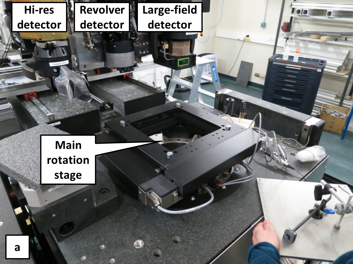
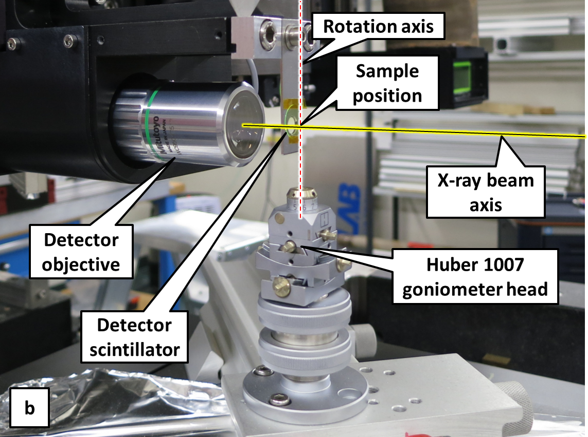
Each of the microtomographs (Fig. 1) has two air-bearing tomography rotation stages. The standard stage is a model RT500S (LAB Motion Systems, Leuven, Belgium) with a central hole of diameter 250 mm for samples or environments requiring space far underneath the X-ray beam axis. An XY stage on top of the rotation allows for centering of the sample on the rotation axis. A smaller but faster rotation stage from the same supplier (model RT150S) is available for ultrafast tomography.
Both rotations are mounted on a common slab with a vertical travel range of 120 mm. Underneath, a horizontal transverse air-bearing translation driven by a linear motor can be used to change between rotation stages, center the rotation axis on beam and detector, and move the sample in and out of the beam for the acquisition of flatfield images.
While typical microtomography scans on ANATOMIX take a few minutes, scans can be much faster in experiments optimized for speed. Fast tomography can currently go up to approximately one scan per second with the RT500S standard stage and a pco.dimax HS4 camera (PCO AG, Kelheim, Germany). The RT150S stage is specified up to 13 rps, and first tests for ultrafast tomography have been conducted at acquisition rates of 18 tomography scans per second.
All scans are performed on the fly, i.e., the rotation stage does not stop rotating during acquisition; the synchronization of motorized axes and detector is usually obtained through the generic Flyscan architecture developed at SOLEIL [6]. The user interface for experiment control is based on Spyc, an iPython-based command-line and scripting environment at SOLEIL. Tomography-specific macros developed at the PSICHÉ beamline provide tools for easy sample alignment and scan setup, as well as a common user experience for both beamlines.
A local computer cluster for reconstruction and storage, with 5 computing nodes and 300 TB storage capacity reconstructs a standard (2048)3-voxel volume in 3 minutes, using the reconstruction software PyHST2 [7] (ESRF, Grenoble, France). A Python script is used to pre-process data and set parameters of the reconstruction; here too, ANATOMIX benefits from developments on PSICHÉ and both beamlines provide a common user interface.
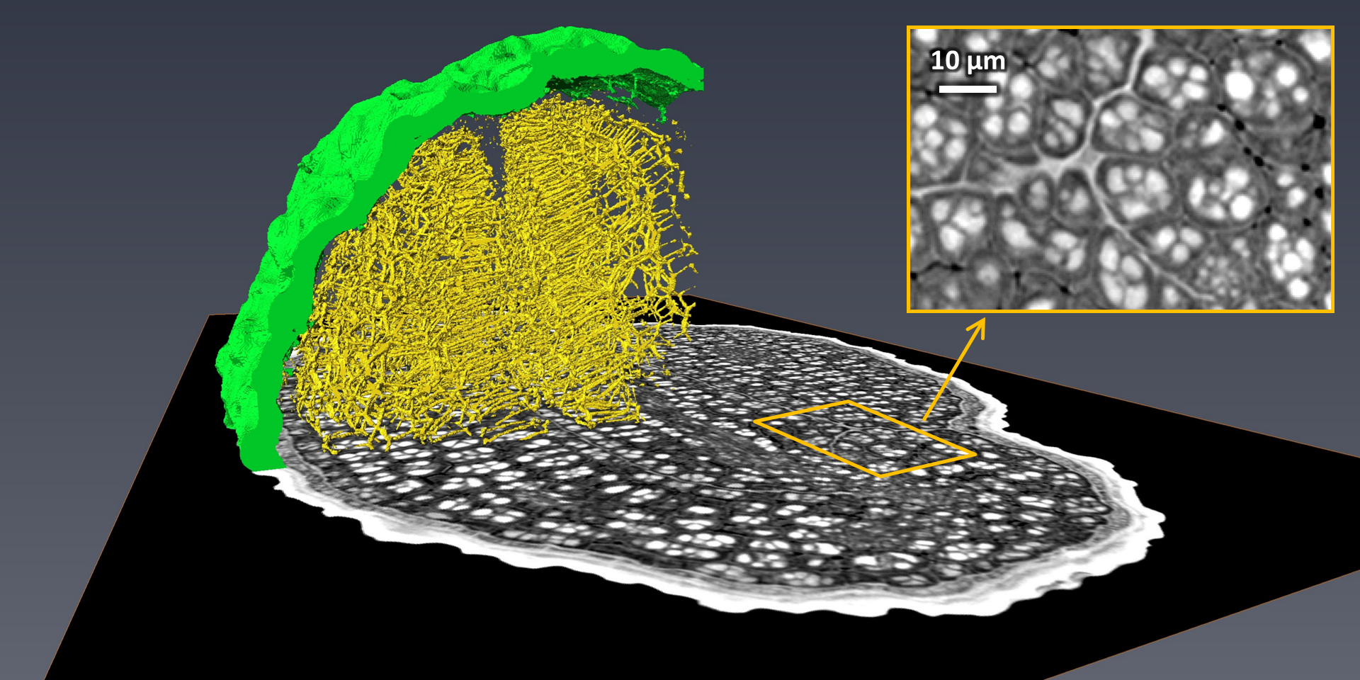
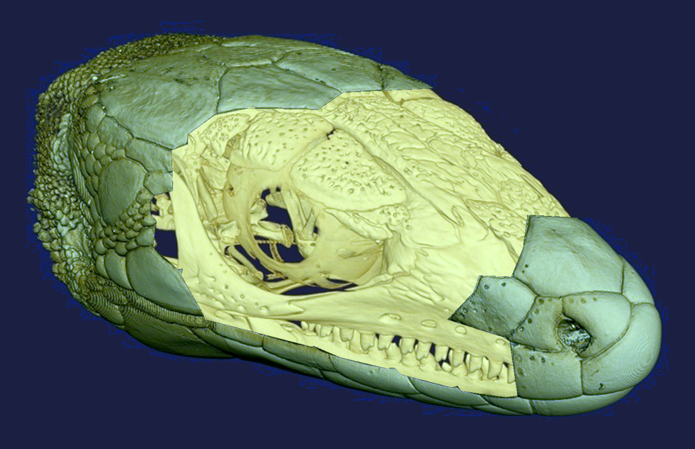
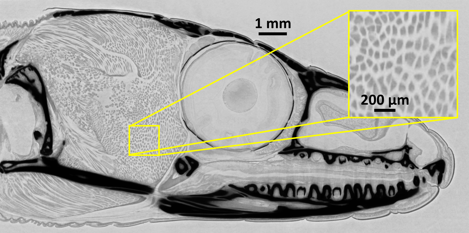
Figures 2 and 3 show two examples of phase-contrast tomography, one at high resolution and one for a relatively large object, demonstrating some of the capabilities of the instrument. User experiments conducted on the beamline include studies from the vast domain of materials science, such as welding processes for fiber-reinforced composites [8], fundamental processes governing the drying of wood [9] or the way archeological textiles are preserved by mineralization in certain environments [10]. Roughly 20% of user projects involve sample environments for in-situ testing, for example for mechanical tests on novel materials for civil engineering [11] or to follow the evolution of the microstructure of frozen foods during freeze-thaw cycles [12]. The second big scientific domain served by the beamline is the biomedical field, which particularly benefits from the good phase-contrast conditions in studies of both soft tissue [13, 14, 15] and systems containing calcified tissue and prosthetic or other biocompatible materials [16].
ANATOMIX is an Equipment of Excellence (EQUIPEX) funded by the Investments for the Future program of the French National Research Agency (ANR), project NanoimagesX, grant no. ANR-11-EQPX-0031.
References
References
- [1] King A, Guignot N, Zerbino P, Boulard E, Desjardins K, Bordessoule M, Leclerq N, Le S, Renaud G, Cerato M, Bornert M, Lenoir N, Delzon S, Perrillat J P, Legodec Y and Itié J P 2016 Rev. Sci. Instrum. 87 093704
- [2] Weitkamp T, Scheel M, Giorgetta J L, Joyet V, Le Roux V, Cauchon G, Moreno T, Polack F, Thompson A and Samama J P 2017 J. Phys. Conf. Series 849 012037
- [3] Scheel M, Perrin J, Koch F, Daniel G, Giorgetta J L, Cauchon G, King A, Yurgens V, Le Roux V, David C and Weitkamp T 2020 Proceedings SRI2021 submitted (Preprint https://doi.org/10.48550/arXiv.2002.03242)
- [4] Paganin D, Mayo S C, Gureyev T E, Miller P R and Wilkins S W 2002 J. Microscopy 206 33–40
- [5] Desjardins K, Scheel M, Giorgetta J L, Weitkamp T, Menneglier C and Carcy A 2018 Proceedings of the 10th International Conference on Mechanical Engineering Design of Synchrotron Radiation Equipment and Instrumentation (MEDSI 2018), Paris, France, 25–29 June 2018 ed Tavakoli K, Giorgetta J L, Jobert N, Kay J, Schaa V R W and Tilmont M (Geneva, Switzerland: JACoW Publishing) pp 355–357 ISBN 978-3-95450-207-3
- [6] Leclercq N, Bisou J, Blache F, Langlois F, Lê S, Medjoubi K, Mocuta C and Poirier S 2015 Proceedings, 15th International Conference on Accelerator and Large Experimental Physics Control Systems (ICALEPCS 2015): Melbourne, Australia, October 17-23, 2015 ed Corvetti L, Riches K and Schaa V R W p WEPGF056
- [7] Mirone A, Brun E, Gouillart E, Tafforeau P and Kieffer J 2014 Nucl. Instrum. Methods B 324 41–48
- [8] Mofakhami E, Tencé-Girault S, Perrin J, Scheel M, Gervat L, Ovalle C, Laiarinandrasana L, Fayolle B and Miquelard-Garnier G 2020 Polym. Test. 85 106454
- [9] Penvern H, Zhou M, Maillet B, Courtier-Murias D, Scheel M, Perrin J, Weitkamp T, Bardet S, Caré S and Coussot P 2020 Phys. Rev. Appl. 14 054051
- [10] Reynaud C, Thoury M, Dazzi A, Latour G, Scheel M, Li J, Thomas A, Moulhérat C, Didier A and Bertrand L 2020 Proc. Natl. Acad. Sci. U. S. A. 117 19670–19676
- [11] Ducoulombier N, Chateau C, Bornert M, Caron J F, Aimedieu P, Weitkamp T, Perrin J, King A and Scheel M 2020 Strain 56 e12347
- [12] Zennoune A, Latil P, Ndoye F T, Flin F, Perrin J, Geindreau C and Benkhelifa H 2021 Foods 10 2915
- [13] Rodgers G, Kuo W, Schulz G, Scheel M, Migga A, Bikis C, Tanner C, Kurtcuoglu V, Weitkamp T and Müller B 2021 J. Neurosci. Methods 364 109354
- [14] Rodgers G, Tanner C, Schulz G, Migga A, Kuo W, Bikis C, Scheel M, Kurtcuoglu V, Weitkamp T and Müller B 2022 J. Neurosci. Methods 365 109385
- [15] Ben Zemzem A, Liang X, Vanalderwiert L, Bour C, Romier-Crouzet B, Blaise S, Sherratt M, Weitkamp T, Dauchez M, Baud S, Passat N, Debelle L and Almagro S 2022 Int. J. Mol. Sci. 23 3250
- [16] Jung O, Hesse B, Stojanovic S, Seim C, Weitkamp T, Batinic M, Goerke O, Kačarevic Peric Ž, Rider P, Najman S and Barbeck M 2021 Int. J. Mol. Sci. 22 12567