Gravitational light deflection
in Earth-based laser cavity experiments
Abstract
As known from Einstein’s theory of general relativity, the propagation of light in the presence of a massive object is affected by gravity. In this work, we discuss whether the effect of gravitational light bending can be observed in Earth-based experiments, using high-finesse optical cavities. In order to do this, we theoretically investigate the dynamics of electromagnetic waves in the spacetime of a homogeneous gravitational field and give an analytical expression for the resulting modifications to Gaussian beam propagation. This theoretical framework is used to calculate the intensity profile at the output of a Fabry-Pérot cavity and to estimate the imprints of Earth’s gravity on the cavity output signal. In particular, we found that gravity causes an asymmetry of the output intensity profile. Based on that, we discuss a measurement scheme, that could be realized in facilities like the GEO600 gravitational wave detector and the AEI 10 m detector prototype.
I Introduction
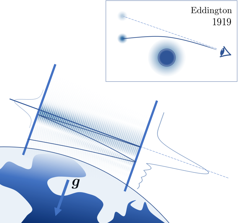
One century ago, one of the most famous predictions of Einsteins theory of gravitation was approved. Two observational expeditions led by A. S. Eddington and C. Davidson observed the stellar light deflection during the solar eclipse of 1919 Einstein16 ; Edd19 . Since then a number of astrophysical observations, i.e. of gravitational lensing, confirmed the gravitational light bending effect astro1 ; astro2 ; astro3 . In contrast to the variety of astrophysical confirmations, much less is reported about gravitational light deflection in Earth-based experiments Thorne77 ; Sivi07 ; Sivi08 ; Rich19 . Today, such experiments likely become possible owing to the advances in high-finesse optical cavities. These cavities are essential to the nowadays most accurate measurement devices, e.g. optical clocks, high resolution spectroscopy lasers and gravitational wave detectors Harry2010 ; Acernese2015 ; Somiya2012 ; Kessler2012 ; Audley2017 . Due to the increasing demand for precision in these experiments, the finesse of laser stabilization cavities underwent a tremendous improvement towards during the last decades Ludlow2007 ; Kessler2012 ; Matei2017 . Moreover, the ongoing research in advanced mirror technologies, like crystalline coatings Cole2016 ; Cole2013 ; Gregory2012 or etalons Dickmann2018-2 ; etalons1 ; etalons2 is promising for further improvements towards even higher finesses.
In this work, we propose to use high-finesse cavities to measure gravitational effects. If such a cavity is subjected to a gravitational field, the light propagation inside the cavity slightly changes and the light beam literally falls down while it is caught between two highly reflective mirrors. This results in an asymmetric cavity output signal, that is expected to be measurable in high-finesse cavities, see Fig. 1. The fact, that the properties of the underlying structure of spacetime are imprinted on the intensity profile at the cavity output, may help to probe the gravitational interaction of light and matter at the laboratory scale.
The coupling of light to matter is one consequence of the Einstein equivalence principle. Recent experiments, like the Galileo satellites Doresa and Milena probe the Einstein equivalence principle by redshift effects on the long range motion of an object Galileo1 ; Galileo2 . Unlike that, our proposed experiment could test the coupling of light to gravity at small scales, using the gravitational light bending effect, which exceeds redshift effects by many orders of magnitude. Moreover, in comparison to the Eddington experiment, where Sun’s gravity acts as a scattering potential for the long range propagation of light, in a cavity the effect of light deflection can be investigated directly within the interaction region of the light beam and the gravitational field of our planet. Therefore, the investigation of cavity internal light bending may enable a wide range of Earth-based tests of general relativity at the laboratory scale in a controlled and reproducible experimental environment.
II Light propagation in a homogeneous gravitational field
In what follows, we will build up a formalism, that allows us to investigate the influence of gravity on a laser beam with Gaussian intensity profile, that enters a horizontal Fabry-Pérot cavity. Before we discuss this scenario, however, we have to develop the formalism from the basic principles of light propagation in a gravitational field. Within the framework of classical electromagnetism, the propagation of light is governed by Maxwell equations. This set of differential equations for the electric and magnetic fields and , can be rewritten in terms of the vector and scalar potentials and . Considering Lorenz gauge condition, in the case of freely propagating light, the scalar potential is determined by the vector potential, from which the fields and can be obtained. This way, the set of Maxwell equations reduces further to a wave equation that in the flat spacetime of an inertial observer reads . Here is the speed of light, while is the derivative with respect to time and is the nabla operator.
In the presence of a gravitational field, however, the properties of spacetime change, which leads to modifications of the wave equation Wald . In the case of the approximately homogeneous gravitational field of the Earth, characterized by the acceleration Remark3 ; Rind60 ; Rind66 this modified wave equation reads
| (1) |
where differs from the usual nabla operator by a factor, that accounts for the gravitational light deflection and redshift. Here, we have considered effects of gravity only to linear order in the dimensionless parameter , which is in the range of for typical length scales of the experiment. Moreover, has to be small in comparison to the Earth’s radius, such that the gravitational field can be considered as homogeneous.
The modified wave equation (1) is a linear partial differential equation for the vector potential . This means that a superposition of solutions to (1) also solves the equation. Under the assumption of quasi scalar beam propagation, therefore, any solution of the wave equation can be constructed by a superposition of the scalar basis functions
| (2) | |||
that solve Eq. (1) for a specific frequency constant and a constant wave vector , which are connected via the dispersion relation Remark1 . We find that the behavior of the wave in -direction, which is chosen along the acceleration vector , is described by a damped Airy -function (cf. Sivi07 ; Sivi08 ). The gravitational effects enter this expression via the damping term and the quantity . In the case , the basis functions (2) resemble the well-known plane wave solutions , which describe light propagation in the spacetime of an inertial observer.
III Gravitational effect on Gaussian beam propagation
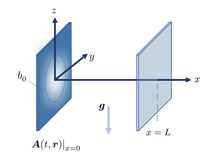
With the complete set of basis functions (2), we are able to model light propagation in a homogeneous gravitational field for any boundary condition Hunt81 . In this paper in particular, we consider a typical experimental setup, where a -polarized laser beam with Gaussian intensity profile enters a Fabry-Pérot cavity. For this setup, the vector potential at the input mirror, located at , is given by
| (3) |
where is a constant vector pointing into -direction and is the waist of the beam, see Fig. 2. For our further analysis, it is convenient to expand (3) in terms of the basis functions (2), see Vallee . This expansion reads , where the coefficients
| (4) | |||
are found by projecting the boundary condition to the complex conjugated basis functions . The first line of this expression is the Fourier transformation of the Gaussian profile (3). In the presence of gravity, however, also contains an Airy -function in the second line, which becomes unity for , such that we recover the result of standard Fourier optics in the case of vanishing gravity.
(a) (b)
The coefficients from Eq. (4) only describe the beam at , which is encoded in the delta function . However, we want the beam to obey the wave equation (1) for all points in space, close to the beam axis. Therefore, we implement the dispersion relation by the replacement of the delta function . At this point, the approximation of paraxial light propagation along the -axis, with the assumption , is taken into account. The new coefficients, denoted as , can be employed to calculate the vector potential of the gravitationally modified Gaussian beam via . The vector potential can be further evaluated by applying methods as presented in Vallee . In result, the beam can be decomposed into
| (5) |
Here describes the propagation of a usual Gaussian beam in the absence of gravity Remark2 , while its gravitational modifications are collected in the complex exponent
| (6) |
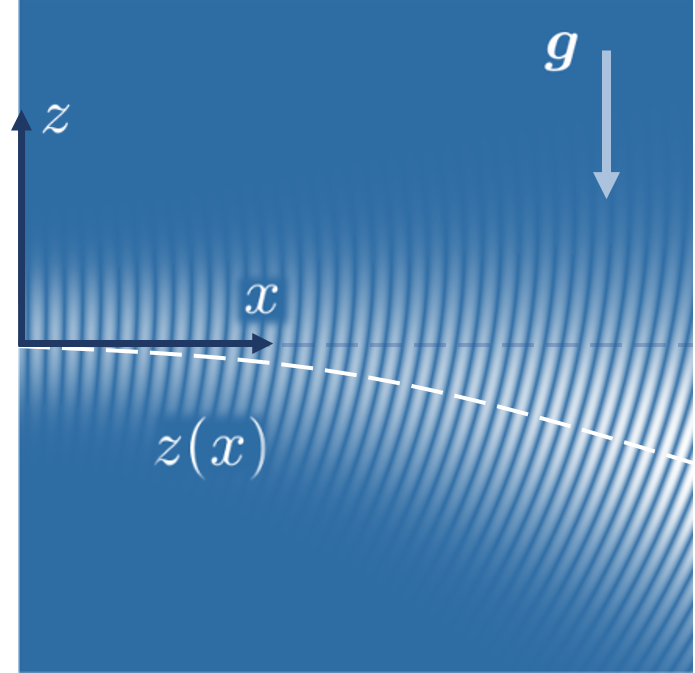
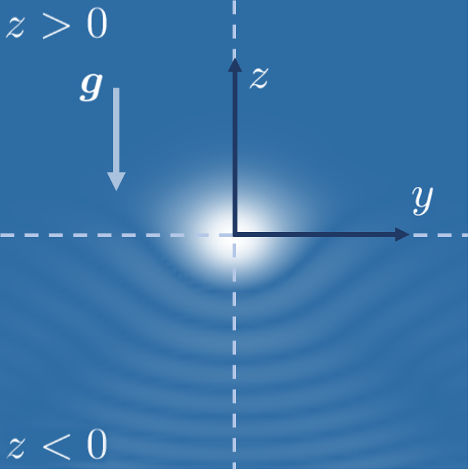
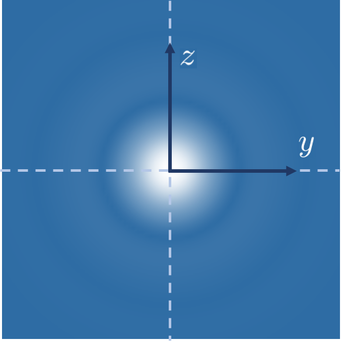
where we introduced , which is the length of propagation in units of the Rayleigh length . The real part of describes the falling of the intensity profile, such that the intensity maximum of the beam follows the parabola , see Fig. 3a. Comparing the real part of with redshift contributions , we find, that the effect of gravitational light bending, is larger by a factor and, therefore, exceeds redshift effects by many orders of magnitude. The imaginary part of gives rise to a -dependent gravitational phase shift , that grows while the beam propagates. As we will discuss hereafter, the falling of the intensity maximum and the gravitational phase shift will have an measurable effect on the output signal of high-finesse Fabry-Pérot cavities.
IV Output signal of a Fabry-Pérot cavity
Previously we have shown, that a homogeneous gravitational field modifies the propagation of a Gaussian beam. Since the deviations from a usual Gaussian beam are small, however, a long propagation distance would be needed to measure the effect under real experimental conditions. In order to overcome this in a laboratory scale experiment, a Fabry-Pérot cavity can be used to accumulate the effect. To analyze this scenario, we assume a cavity, that consists of two identical plane parallel mirrors at the positions and , as shown in Fig. 2. Commonly, a Fabry-Pérot cavity is characterized by its finesse , that is related to the transmittance of the mirrors via Ismail2016 , where determines the number of roundtrips in the cavity.
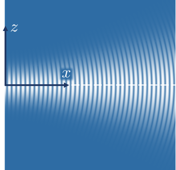
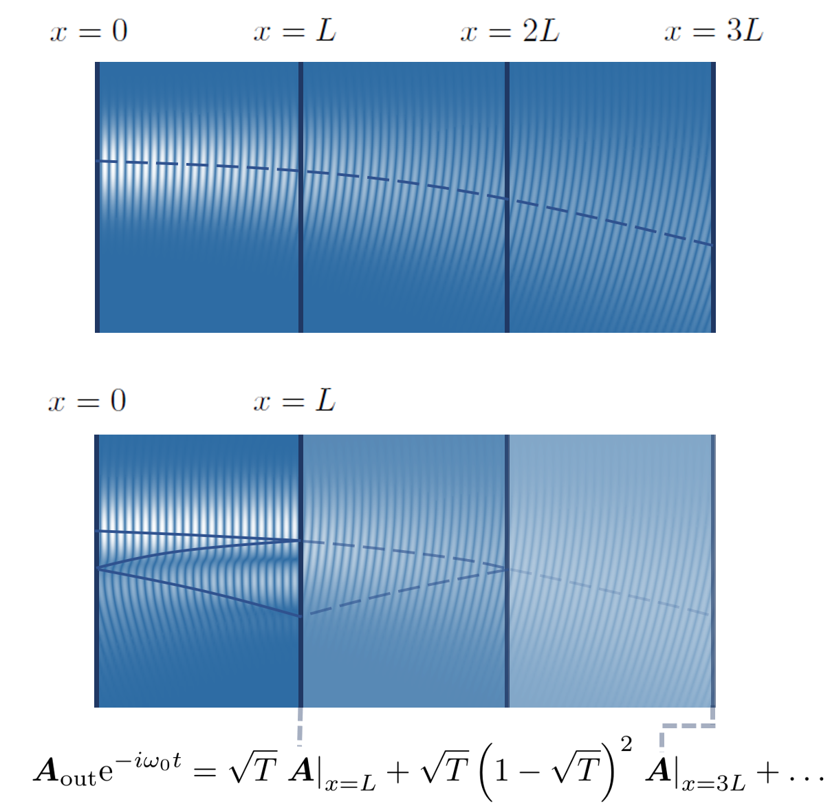
The two planar mirrors only change the direction of propagation along the -axis. This for example means, that the signal at the position of the output mirror after the first two reflections equals the freely propagating beam at the position , as illustrated in Fig. 4. Therefore, the vector potential behind the cavity output mirror can be obtained by the overlay of slices of the modified Gaussian beam
| (7) | |||
where every slice is weighted by the loss per reflection in the cavity.
(a) (b)
With the vector potential (7), we can analyze the properties of the light, that emerges from the Fabry-Pérot cavity. The intensity profile at the cavity output, in paraxial approximation is given by the energy density at the output mirror, that can be expressed by the squared module of the vector potential Remark4 . In fact, the redshift-prefactor of the intensity turns out to be negligible in comparison to the light deflection of the beam that constitutes the leading effect on the structure of the intensity pattern, illustrated in Fig. 5. Furthermore, integrating the intensity between two heights and gives the power at the corresponding section of the output mirror. The total output power , therefore, is obtained by integrating the intensity over the whole mirror surface.
V Measurement scheme
In order to extract the effect of gravity from the signal, a position sensing detector, i.e. a quadrant detector, can be used. Such a detector measures the power difference between the upper and the lower half-plane of the output mirror. This difference, that can be normalized to the total output power, determines the detection parameter
| (8) |
The measurement of this parameter is limited by the detector photon shot noise, that determines the sensitivity as a function of the total output power by
where is the relative light power variance and is the measurement bandwidth, which we set to the common value of Edelstein1978 . For cavity lengths of cm to m scale, the detector photon shot noise is the dominant limitation of sensitivity in the proposed experiment, assuming optimized measurement frequencies and experimental parameters such as mirror mass, seismic decoupling and optical coatings Robinson2019 ; Dooley2015 ; Notcutt06 . For larger cavities, like the GEO600 facility, with increased finesse, cryogenic mirrors or meta-mirrors would be needed to suppress the mirror coating thermal noise below the photon shot noise. Cole2016 ; Dickmann2018-2 .
In what follows, we will use the signal-to-noise ratio as a criterion for the measurability of the cavity internal gravitational light bending effect. In order to obtain the predicted signal of the quadrant detector, the summation in Eq. (7) and the power integrals in Eq. (8) are evaluated numerically.
VI Results and discussion
The equations (7) - (V) allow us to analyze the gravitational light bending effect for a wide range of experiments with Fabry-Pérot cavities. Therefore, in this rapid communication we consider three specific showcase scenarios for Earth-based cavity designs: (i) a horizontal -Fabry-Pérot cavity with a finesse between and , (ii) a hypothetical Fabry-Pérot version of the GEO600 facility with an improved finesse between and and (iii) the 10 m gravitational wave detector prototype at the Albert-Einstein institute Hannover (AEI) with the same finesse values as for GEO600. Our results are presented in the Table 1, where we give the parameter and the ratio for each scenario. Moreover, the inverse signal-to-noise ratio can be interpreted as the relative accuracy of hypothetical measurements of the gravitational acceleration using the light bending effect. Combining Eq. (8) and (V), the the order of magnitude of the effect can be estimated
| (10) |
where, in order to get the exact value, the factor depending on the cavity length in units of the Rayleigh length and the finesse has to be evaluated. In what follows, we will discuss the the parameter and the signal-to-noise ratio for the cavity settings mentioned above.
| Properties | [ppb] | |||||
|---|---|---|---|---|---|---|
| (i) | m | |||||
| mm | ||||||
| nW | ||||||
| (ii) | m | |||||
| mm | ||||||
| W | ||||||
| (iii) | m | |||||
| mm | ||||||
| W |
First, we consider the 21 cm-Fabry-Pérot cavity. Due to the combination of the small beam waist of mm Matei2017 , low laser power in the nano watt range, e.g nW Robinson2019 , and the short length of the cavity, even for higher finesses of no cavity internal gravitational light bending effect can be measured in this setup. This can be seen from Table 1, where the quadrant detector signal is less than ppb, which is much smaller than the detector noise. However, gravity may set a limit on the phase stability of comparable laser stabilization cavities, as we will discuss in a future publication Ulbricht20xx .
The effect can be enhanced dramatically if one uses longer cavities and larger beam waists. To show this, we discuss a hypothetical Fabry-Pérot version of the GEO600 facility with a 600 m base line: The substitution of the GEO600 beam splitter by a mirror, which is comparable to the current GEO600 mirrors Grote2008 , would transform the Michelson interferometer into a Fabry-Pérot cavity. This configuration could be operated with a laser beam waist of mm Heinert2014 . Considering a finesse of and keeping the current GEO600 input power of 3.2 W Grote2008 , the signal is expected to be 42 ppb with a signal-to-noise ratio of up to 90 at a measurement bandwidth of 1 Hz. While increasing the finesse up to could enhance the signal to 178 ppb with a signal-to-noise ratio of up to 400, cryogenic mirrors or meta-mirrors would be needed to reach this sensitivity. Moreover, by assuming the planned GEO-HF update Dooley2015 and the associated increased laser power by a factor of 4, the signal-to-noise ratio would be enhanced further by a factor of 2.
The needed size of the experiment scales down, if a higher laser power is used. As a third example we, therefore, discuss the AEI 10 m prototype, that can be operated with a powerful 38 W input laser Westphal2012 . Like in the case of GEO600, the substitution of the beam splitter by a highly reflective mirror would turn the device into a Fabry-Pérot interferometer. Considering a beam waist of mm bw3 and a finesse of , the detector output signal is expected to be 2.7 ppb with a signal-to-noise ratio of 20 at a 1 Hz bandwidth. Thus, a Fabry-Pérot version of the AEI 10 m prototype would be suitable for testing the cavity internal gravitational light bending effect at laboratory scales.
VII Summary
In this work, we lay down a theory for the propagation of light in a homogeneous gravitational field. For this, we solved the wave equation in Rindler spacetime to first order in and applied the result to the propagation of a Gaussian beam. We found, that the presence of gravity leads to a falling of the beam intensity profile and an additional phase shift. Both effects increase while the beam propagates.
In order to study the gravitational light bending, we propose to perform measurements in high-finesse Fabry-Pérot cavities, where the effect accumulates due to the multiple roundtrips of the light between the mirrors. For such a setup, we applied our theory to calculate the intensity profile at the cavity output. In order to estimate whether gravitational effects can be observed in the output signal of nowadays or future cavity settings, we considered three experimental scenarios. Based on this we found, that cavity designs like the GEO600 gravitational wave detector and the 10 m detector prototype at Albert-Einstein-institute Hannover are highly suitable for the measurement of the gravitational light bending effect. Moreover, we found that the effect of light bending for a Gaussian beam is enhanced by a factor in comparison to redshift effects. We suppose, that the realization of the proposed experiment and the validation of the effect can open a road to to test the interaction of light and gravity at small scales in Earth-based cavity experiments.
Acknowledgements.
The authors acknowledge the support by the Deutsche Forschungsgemeinschaft (DFG, German Research Foundation) under Germany’s Excellence Strategy - EXC-2123 QuantumFrontiers - 390837967.References
- (1) A. Einstein, The Foundation of the General Theory of Relativity, Annalen der Physik 49, 769 (1916).
- (2) F. W. Dyson, A. S. Eddington, and C. Davidson, A determination of the deflection of light by the sun’s gravitational field, from observations made at the total eclipse of May 29, Philosophical Transactions of the Royal Society of London. Series A, 220, 291 (1920).
- (3) A. Einstein, Lens-like action of a star by the deviation of light in the gravitational field, Science 84 No. 2188, 506 (1936).
- (4) F. Zwicky, Nebulae as Gravitational Lenses, Phys. Rev. 51, 290 (1937).
- (5) D. Walsh, R. F. Carswell, and R. J. Weymann, 0957 + 561 A, B: twin quasistellar objects or gravitational lens?, Nature 279, 381 (1979).
- (6) V. B. Braginsky, C. M. Caves and K. S. Thorne, Laboratory experiments to test relativistic gravity, Phys. Rev. D 15, 2047 (1977).
- (7) G. A. Siviloglou, J. Broky, A. Dogariu, and D. N. Christodoulides, Observation of Accelerating Airy Beams, Phys. Rev. Lett. 99, 213901 (2007).
- (8) G. A. Siviloglou, J. Broky, A. Dogariu, and D. N. Christodoulides, Ballistic dynamics of Airy beams, Opt. Lett. 33, 207 (2008).
- (9) M. Richard, Free-fall of photons in a planar optical cavity, J. Phys. Commun. 3, 045007 (2019).
- (10) G. M. Harry, LIGO Scientific Collaboration, et al., Advanced LIGO: the next generation of gravitational wave detectors, Class. Quantum Grav. 27, 084006 (2010).
- (11) F. Acernese, M. Agathos, K. Agatsuma, et al., Advanced Virgo: a second-generation interferometric gravitational wave detector, Class. Quantum Grav. 32, 024001 (2015).
- (12) K. Somiya, Detector configuration of KAGRA–the Japanese cryogenic gravitational-wave detector, Class. Quantum Grav. 29, 124007 (2012).
- (13) T. Kessler, C. Hagemann, C. Grebing, T. Legero, U. Sterr, F. Riehle, M. Martin, L. Chen, and J. Ye, A sub-40-mHz-linewidth laser based on a silicon single-crystal optical cavity, Nature Photonics 6, 687 (2012).
- (14) P. Amaro-Seoane, H. Audley, S. Babak, J. Baker, et al., Laser Interferometer Space Antenna, arXiv preprint, arXiv:1702.00786 (2017).
- (15) A. D. Ludlow, et al., Compact, thermal-noise-limited optical cavity for diode laser stabilization at , Opt. Lett. 32, 641-643 (2007).
- (16) D. G. Matei, et al., 1.5 m Lasers with Sub-10 mHz Linewidth, Phys. Rev. Lett 118, 263202 (2017).
- (17) G. D. Cole, et al., High-performance near- and mid-infrared crystalline coatings, Optica 3, 647 (2016).
- (18) G. D. Cole, W. Zhang, M. Martin, et al., Tenfold reduction of Brownian noise in high-reflectivity optical coatings, Nature Photonics 7, 644 (2013).
- (19) H. Gregory, T. P. Bodiya, and R. DeSalvo, eds. Optical coatings and thermal noise in precision measurement, Cambridge University Press (2012).
- (20) J. Dickmann and S. Kroker, Highly reflective low-noise etalon-based meta-mirror, Phys. Rev. D 98, 082003 (2018).
- (21) A. G. Gurkovsky, et al., Reducing thermal noise in future gravitational wave detectors by employing Khalili etalons, Phys. Lett. A 375, 4147 (2011).
- (22) K. Somiya, et al., Reduction of coating thermal noise by using an etalon., Phys. Lett. A 375, 1363 (2011).
- (23) S. Herrmann, et al., Test of the Gravitational Redshift with Galileo Satellites in an Eccentric Orbit, Phys. Rev. Lett., 121, 231102 (2018).
- (24) P. Delva, et al. Gravitational Redshift Test Using Eccentric Galileo Satellites, Phys. Rev. Lett. 121, 231101 (2018).
- (25) R. M. Wald, General Relativity, University of Chicago Press, Chicago (1984).
- (26) We use the metric in its spatially isotropic form with the line element .
- (27) W. Rindler, Hyperbolic Motion in Curved Space Time, Phys. Rev. Lett. 119, 2082 (1960).
- (28) W. Rindler, Kruskal Space and the Uniformly Accelerated Frame, American Journal of Physics 34, 1174 (1966).
- (29) Here we allow for real and imaginary valued , what also includes damping in -direction and ensures the completeness of the basis functions with respect to . Due to the asymptotic properties of the Airy -function, negative valued become irrelevant in the limiting case of vanishing and the standard Fourier basis is recovered.
- (30) P. M. Hunt, A continuum basis of airy functions, Molecular Physics, 44, 653 (1981).
- (31) O. Vallée, and M. Soares, Airy Functions and Applications to Physics, Imperial College Press, London (2004).
- (32) The expression for the Gaussian beam reads .
- (33) N. Ismail, C. C. Kores, D. Geskus, and M. Pollnau, Fabry-Pérot resonator: spectral line shapes, generic and related Airy distributions, linewidths, finesses, and performance at low or frequency-dependent reflectivity, Optics express 24, 16366 (2016).
- (34) The energy density of the gravitational affected Gaussian beam reads . The scalar potential is determined by the vector potential via Lorenz gauge condition. Thus, the contributions of to the energy density are by a factor smaller than contributions of the vector potential: . The contribution of vanishes at the beam axis and shrinks while the beam propagates. In result the scalar potential does not affect the outcome of the calculations quantitatively.
- (35) W. A. Edelstein, J. Hough, J. R. Pugh, and W. Martin, Limits to the measurement of displacement in an interferometric gravitational radiation detector, J. Phys. E: Sci. Instrum. 11, 710 (1978).
- (36) J. M. Robinson, E. Oelker, W. R. Milner, W. Zhang, T. Legero, D. G. Matei, F. Riehle, U. Sterr, and J. Ye, Crystalline optical cavity at 4 K with thermal-noise-limited instability and ultralow drift, Optica 6, 240 (2019).
- (37) L. K. Dooley, et al., Status of GEO 600, J. Phys.: Conf. Ser. 610, 012015 (2015).
- (38) M. Notcutt, at al., Contribution of thermal noise to frequency stability of rigid optical cavity via Hertz-linewidth lasers, Phys. Rev. A 73, 031804 (2006).
- (39) S. Ulbricht, J. Dickmann, R. A. Müller, S. Kroker, and A. Surzhykov, In preparation.
- (40) H. Grote, et al., The status of GEO 600 Class. Quantum Grav. 25, 114043 (2008).
- (41) D. Heinert, K. Craig, H. Grote, S. Hild, H. Lück, R. Nawrodt, D. A. Simakov, D. V. Vasilyev, S. P. Vyatchanin, and H. Wittel, Thermal noise of folding mirrors, Phys. Rev. D 90, 042001 (2014).
- (42) T. Westphal, et al., Design of the 10 m AEI prototype facility for interferometry studies, Applied Physics B, 106, 551 (2012).
- (43) C. Gräf, Optical Design and Numerical Modeling of the AEI 10m Prototype sub-SQL Interferometer, Dissertation, Hannover U. (2013).