Nanofiber based displacement sensor
Abstract
We report on the realization of a displacement sensor based on an optical nanofiber. A single gold nano-sphere is deposited on top of a nanofiber and the system is placed within a standing wave which serves as a position ruler. Scattered light collected within the guided mode of the fiber gives a direct measurement of the nanofiber displacement. We calibrated our device and found a sensitivity up to 1.2 nm/. As an example of application, a mechanical model based on the Mie scattering theory is then used to evaluate the optically induced force on the nanofiber by an external laser and its displacement. With our sensing system, we demonstrate that an external force of 1 pN applied at the nanofiber waist can be detected.
I Introduction
Position sensing with micro or nano-meter resolution is widely used both in scientific research and for industrial applications muschielok2008nano ; andrecka2009nano . In order to probe weak forces the miniaturization of the devices towards the nanoscale is one of the main approaches de2017universal ; de2018eigenmode . Nanowires feng2007very , carbon nanotubes conley2008nonlinear , and graphene eichler2011nonlinear were successfully demonstrated as potential materials for position sensing. Several hybrid systems were also used including nanomechanical oscillators coupled to a whispering gallery mode resonator anetsberger2009near , superconducting microwave cavities cooled by radiation pressure damping teufel2008dynamical , silicon nanowire mechanical oscillators for NMR force sensing nichol2012nanomechanical and nanomechanical oscillators combined with single quantum objects arcizet2011single .
Pico-meter sensitivity has been achieved using a quantum point contact as a scanned charge-imaging sensor (sensitivity of 3 pm/ cleland2002nanomechanical ) or using a nanorod placed within a Fabry-Pérot microcavity (sensitivity of 0.2 pm/ favero2009fluctuating ).
Here, we propose to use an optical nanofiber as a nanometric displacement sensor which is all optical and can operate at room temperature and in free space. The optical nanofiber is an air-cladding guiding system with subwavelength diameter, which allows light to be transmitted outside the fiber in the form of evanescent field. In the recent years, the optical properties of nanofibers have been widely used for atomic fluorescence investigation nayak2007optical , atom trapping vetsch2010optical ; corzo2016large , quantum optics and quantum information yalla2012efficient , chiral quantum optics lodahl2017chiral , and optical resonators ding2019fabrication .
Interestingly, a nanofiber has also remarkable mechanical properties, including a small mass, on the order of 0.1 g/m and a high sensitivity to vibrations and weak forces. In this work, we combine the optical and mechanical properties of a nanofiber to create a unique sensing device for displacement measurements and optomechanical applications. By depositing a nanoparticle on top of a nanofiber and placing this system in an optical standing wave positioned transversely as a ruler, we report an absolute sensitivity up to 1.2 nm/. Using the Mie scattering theory, we evaluate the force induced on the nanofiber by an external laser and demonstrate that a sensitivity of 1 pN can be achieved. Force sensing with pico-newton precision can be used as a sensor for optomechanics larre2015optomechanical , biophysics investigations freikamp2016piconewton and molecule mechanics finer1994single .
The article is organized as follows. We first introduce the experimental setup and describe the calibration procedure used to measure the sensitivity. We then present the experimental Allan deviation of our device, measured up to 10 minutes with a integration time. In the second part, we present a possible application of our sensor to detect radiation pressure force. We propose a mechanical model to estimate the displacement of our sensor under an optically induced force, and we show that the full Mie scattering theory must be taken into account for accurate predictions. Finally we model the two orthogonal polarisations as a signature of the anisotropy of the system.
II Measuring the absolute displacement of an optical nanofiber
The general idea of our approach is to place an optical nanofiber within a transverse standing wave and to monitor the amount of scattered light in the guided mode of the fiber in order to infer its position. Optical nanofibers are optical waveguides with a sub-wavelength diameter. By carefully tapering a commercial single-mode fiber to sub-wavelength diameter, the adiabatic conversion of the HE mode can be achieved ward2014contributed ; solano2017optical ; ding2010ultralow . In the sub-wavelength region, the optical mode is guided in air and a strong evanescent field is present outside of the nanofiber. This has the crucial advantage that light can be coupled in and out with a scattering object deposited, in the evanescent field, on the surface of the nanofiber.
We fabricated a tapered optical nanofiber with a diameter of 300 nm and more than 95% transmission (at 532 nm), following the method detailed in ward2014contributed and used in joos2018polarization . To observe scattering, we overlapped a transverse standing wave with the nanofiber, by retro-reflecting a standard laser diode at 532 nm on a mirror (see Fig. 1a)). The mirror is mounted on a piezo-transducer, so that we can scan it in the longitudinal axis to move the standing wave envelope around the nanofiber position. In order to guarantee a high contrast of the standing-wave, we verified that the coherence length of the laser is much longer than the distance between the mirror and the nanofiber. In practice, this is not a stringent condition for standard narrow linewidth laser diode.
In this configuration the light scattered inside the guided mode of the nanofiber is only due to the rugosity of the nanofiber and is extremely low. To guarantee a high signal to noise ratio on the detection and therefore a high displacement sensitivity, we have deposited a gold nano-sphere on the nanofiber to enhance scattering (see Fig. 1c). The nano-sphere has a radius of 50 nm. The deposition is done by filling a highly dilute solution of gold nano-spheres inside a micro-pipette and touching repeatedly the nanofiber with the meniscus at the extremity of the pipette. We continuously inject light inside the nanofiber to monitor the scattered light from the deposition region. As seen in Fig. 1d, the scattered light increases dramatically after the deposition of the gold nano-sphere yalla2012efficient .
The nanofiber is mounted on a custom holder, which has a bending piezo transducer at one side, in order to control its tension. Finally, we placed the system under vacuum to avoid dust particle deposition and perturbations from air-flows. The scattered light guided into the fiber is detected with an avalanche photodiode to have high detection efficiency (50) and fast response up to 100 MHz.
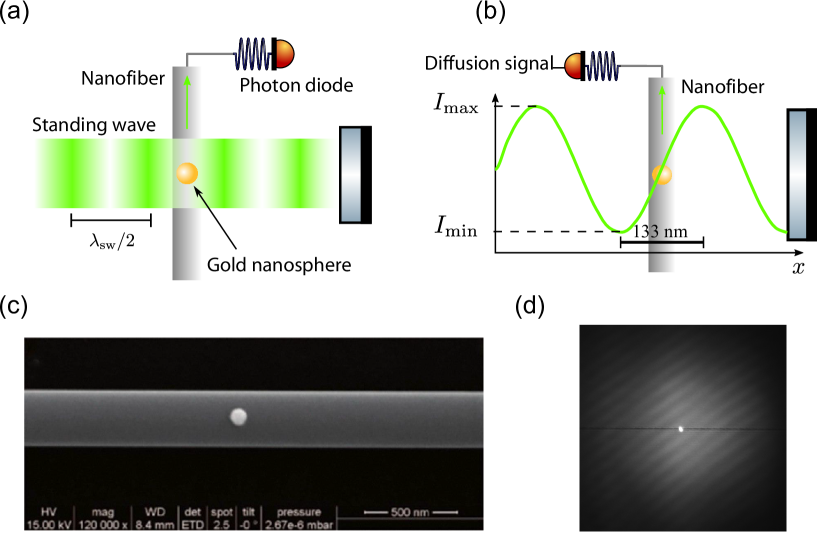
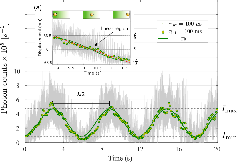
To calibrate the displacement, we first scan the standing wave around the nano-sphere. The signal oscillates with a period corresponding to nm. The visibility of the standing wave is defined as where and are the minimum and maximum detected intensity.
A sinusoidal fit of the experimental data is presented in Fig. 2 and gives a visibility of 0.71 calculated using the the measurement with 100 ms integration time. In Fig. 2, we can see the vibrations in the environment through the sensing system. These vibrations have high amplitude which widened the scan curve. For this measurement a relatively long integration time (100 ms) has been used and therefore high frequency noise reduces the contrast below 1. For small displacements (), the most sensitive region of the standing wave is obviously the linear part (see Fig. 1b). In this region, the calibration of the displacement as a function of the scattered light is obtained by fitting the region with a linear model.
III Sensitivity of the system
The sensitivity of our system is linked to two main factors: at short integration time, the noise essentially comes from the fluctuations of the scattered light and the mechanical oscillations of the nanofiber and, at long time scale, we observed a drift caused by a temperature shift in the environment which displaces the standing wave.
A quantitative description of the sensitivity is given in Fig. 3 by presenting the Allan deviation. The Allan deviation is typically used to measure frequency stability in oscillators but it can also be implemented in the time domain. Differently from standard deviation which gives only one value for a given integration time, Allan deviation gives access to the whole noise spectrum at different frequencies detected in our system. We follow the equation given by allan1981modified . is the measured time history of photon counts with a sample period of . We divide the data sequence (photon arrival time on the photodiode) into clusters of time . The averaging time is set as , where the averaging factor is a group of integers from 1 to . was used in calculation. The Allan deviation is calculated using averages of the output rate samples over each time cluster.
| (1) |
or in practice:
| (2) |
where is the integrated photon counts. is the sample points.
According to the fit in Fig. 2, we got the correspondence between fiber displacement and photon count, which is about 2.9 kcounts/nm. Therefore, the Allan deviation is given in unit nm/ in Fig. 3.
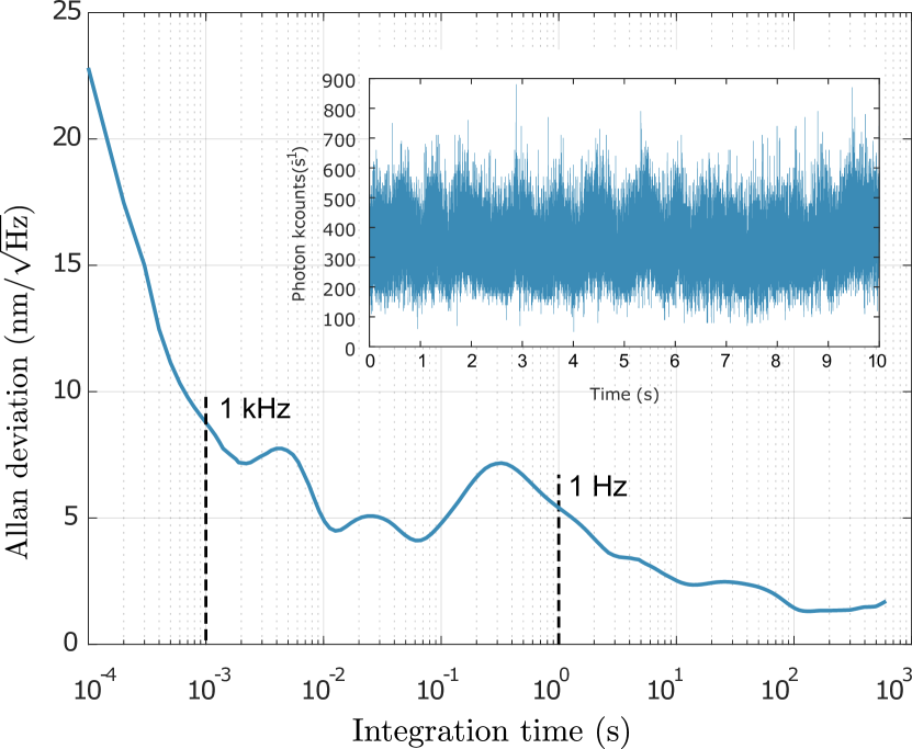
On Fig. 3, three main regions can be identified: i) at integration time shorter than 1 ms (frequency higher than 1 kHz) where the sensitivity increases with the integration time (lower ), ii) at integration time between 1 ms and 1 s (between 1 kHz and 1 Hz) where we observe a sinusoidal noise with characteristics bumps in the Allan deviation signature of the mechanical modes of the nanofiber, and iii) at integration time longer than 1 s (frequency lower than 1 Hz) where the sensitivity increases again. Finally, at longer integration times than 3 minutes (not shown), the sensitivity decreases again (higher ) due to the thermal drift in the standing wave phase. We can extract two key figures of merit from these data. The resolution at 1 s integration time is 5.1 nm/, and the maximum absolute resolution is 1.2 nm/
IV Displacement of the nanofiber driven by externally applied force
In the second part of this paper, we propose one possible application of our nanofiber displacement sensor for optomechanics experiments. We assess the possibility to detect the radiation pressure force, by estimating theoretically the displacement of the nanofiber when it is driven by an externally applied force and we investigate in particular optically-induced forces based on the Mie theory.
We model the nanofiber as an elastic string of circular section (radius ) with the two ends fixed. The location of the applied force on the nanofiber is an important parameter for the sensitivity to the force. Here, we assume that the force is applied at the middle of the nanofiber waist, i.e. in the most sensitive region, however the model can be extended easily to other positions. First, we take the initial tension on the nanofiber to be zero. The expression of the displacement as function of the applied force is then given by:
| (3) |
where is the Young modulus of silica, and is the length of the nanofiber region bellan2005measurement ; timoshenko1968elements .
It is interesting to evaluate if a radiation pressure force applied by an external pushing laser could be observed using this system with the sensitivity measured earlier. A coarse evaluation can be made using a simple model by considering the nanofiber with radius as a beam with squared section and estimate the force by the differential Fresnel reflections on the sides of the silica beam. In this geometrical approach, the pushing laser is described by its diameter , its power and its intensity . If , the illuminated section of the nanofiber is and the force is
| (4) |
with the speed of light in vacuum and the normal incidence reflection coefficient. With this model, we can estimate the force of a flat top beam of and diameter on a nanofiber of squared section made in silica (optical index of which induces a Fresnel reflection coefficient ):
However, if this simple model is instructive to obtain an order of magnitude of the applied force, it must be refined to take into account the interference and polarization effects. In the following, we use the Mie theory of diffusion to give a more precise estimation of the optical force. We assume a cylindrical nanofiber (radius and index of refraction ) illuminated on normal incidence by a plane wave (with Gaussian envelope of width ).
Two linear polarisations can be used, either parallel or perpendicular to the nanofiber axis. The force given by the Mie theory is mitri2017radiation ; loo2019imaging :
| (5) |
where is a dimensionless quantity which depends on the polarisation. For a linear polarisation parallel to the nanofiber is given by
| (6) |
The geometric coefficient is given by
| (7) |
with is the first order Hankel function and is the first order Bessel function. Similarly, for a linear polarisation perpendicular to the nanofiber, we have
| (8) |
with
| (9) |
.
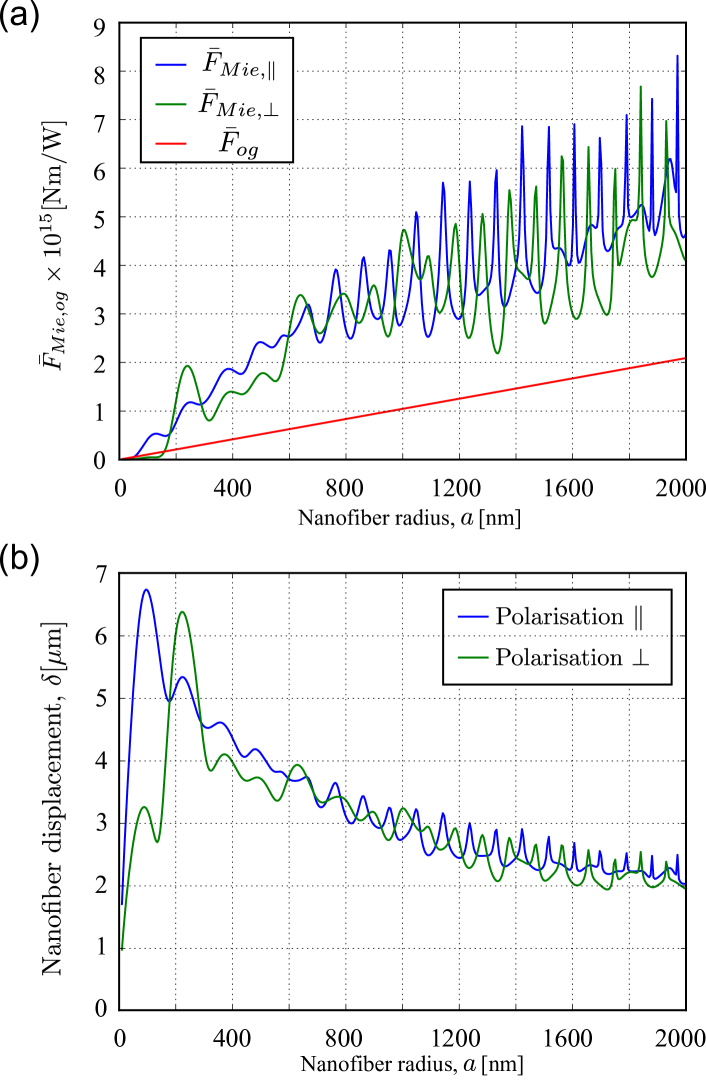
This model is compared numerically to the geometric model in Fig. 4a). It can be observed that the geometric model, represented by the red line in the figure clearly under-estimate the force for both polarisations above a nanofiber diameter of 200 nm. Compared to the geometrical optics model, the Mie scattering model also predicts oscillations in the radiation force as a function of the increasing radius of the nanofiber, which corresponds to an interference between the specularly reflected waves from the edge of the nanofiber and those reflected by its dielectric core. In addition, the radiation force shows dependence on the incident polarization which is characteristic of the anisotropy of the system joos2019complete .
In the following, we use the full model of Mie scattering to estimate the displacement. We inject the expression of the force in the displacement of the nanofiber given by Eq. (3) and we trace the displacement as function of the nanofiber radius in the absence of tension . In this configuration, we predict a displacement on the order of 5 m for both polarisations at fiber diameter around 400 nm. While far exceeds the linear dynamical range introduced in the first part of this paper, we can easily reduce the power of the beam generating the radiation pressure force such that the beam displacement is compatible with the requisite range of our experimental technique (displacement smaller than 266 nm). The minimal force that can be detected with our device is then on the order of 1 pN. Finally, to extend our model, we can include a non-zero initial tension on the fiber. In presence of an initial tension , a correction term can be added to Eq. (3) to determine the force required to induce a displacement of the nanofiber:
| (10) |
The first term is linked to the mechanical properties of silica as the second one is a consequence of the nanofiber tension. As in our experiment, tension might play an important role in the ability of our system for detecting weak force applied on the fiber. Experimentally, we have anticipated this situation by adding a bending piezoelectric transducer to the nanofiber holding mount. This open the way to future investigations of the tension as well as the potential role of damping due to air around the nanofiber.
V Conclusion
In conclusion, we have presented a position sensor based on a gold nano-sphere deposited on a nanofiber and placed within a standing wave. Our sensor can measure the displacement of a nanofiber driven by externally applied force and vibrations. We experimentally calibrated our sensing system and obtained a resolution of 1.2 nm/. We proposed a mechanical model to estimate the response of our sensor to optically-induced pressure force and we found that the sensitivity corresponding to the sensibility of an externally applied force at the nanofiber waist is 1 pN. This optical nanofiber sensor paves the way to realize integrated optomechanical research using this platform, such as the demonstration of superfluidity of light in a photon fluid larre2015optomechanical ; fontaine2018observation .
Acknowledgement
The authors would like to thank Arno Rauschenbeutel for designing an early prototype of this device and for fruitful discussions on the sensitivity measurements. This research is supported by the Emergences Ville de Paris Nano2 project, the Caiyuanpei Programm and the European Union’s Horizon 2020 research and innovation program under grant agreement No 828972. C.D. is supported by a CSC scholarship.
References
- (1) Adam Muschielok, Joanna Andrecka, Anass Jawhari, Florian Brückner, Patrick Cramer, and Jens Michaelis. A nano-positioning system for macromolecular structural analysis. Nature methods, 5(11):965, 2008.
- (2) Joanna Andrecka, Barbara Treutlein, Maria Angeles Izquierdo Arcusa, Adam Muschielok, Robert Lewis, Alan CM Cheung, Patrick Cramer, and Jens Michaelis. Nano positioning system reveals the course of upstream and nontemplate dna within the rna polymerase ii elongation complex. Nucleic acids research, 37(17):5803–5809, 2009.
- (3) Laure Mercier de Lépinay, Benjamin Pigeau, Benjamin Besga, Pascal Vincent, Philippe Poncharal, and Olivier Arcizet. A universal and ultrasensitive vectorial nanomechanical sensor for imaging 2d force fields. Nature nanotechnology, 12(2):156, 2017.
- (4) Laure Mercier de Lépinay, Benjamin Pigeau, Benjamin Besga, and Olivier Arcizet. Eigenmode orthogonality breaking and anomalous dynamics in multimode nano-optomechanical systems under non-reciprocal coupling. Nature communications, 9(1):1401, 2018.
- (5) XL Feng, Rongrui He, Peidong Yang, and ML Roukes. Very high frequency silicon nanowire electromechanical resonators. Nano Letters, 7(7):1953–1959, 2007.
- (6) William G Conley, Arvind Raman, Charles M Krousgrill, and Saeed Mohammadi. Nonlinear and nonplanar dynamics of suspended nanotube and nanowire resonators. Nano letters, 8(6):1590–1595, 2008.
- (7) Alexander Eichler, Joel Moser, Julien Chaste, Mariusz Zdrojek, I Wilson-Rae, and Adrian Bachtold. Nonlinear damping in mechanical resonators made from carbon nanotubes and graphene. Nature nanotechnology, 6(6):339, 2011.
- (8) Georg Anetsberger, Olivier Arcizet, Quirin P Unterreithmeier, Rémi Rivière, Albert Schliesser, Eva Maria Weig, Jörg P Kotthaus, and Tobias J Kippenberg. Near-field cavity optomechanics with nanomechanical oscillators. Nature Physics, 5(12):909–914, 2009.
- (9) JD Teufel, JW Harlow, CA Regal, and KW Lehnert. Dynamical backaction of microwave fields on a nanomechanical oscillator. Physical review letters, 101(19):197203, 2008.
- (10) John M Nichol, Eric R Hemesath, Lincoln J Lauhon, and Raffi Budakian. Nanomechanical detection of nuclear magnetic resonance using a silicon nanowire oscillator. Physical Review B, 85(5):054414, 2012.
- (11) Olivier Arcizet, Vincent Jacques, Alessandro Siria, Philippe Poncharal, Pascal Vincent, and Signe Seidelin. A single nitrogen-vacancy defect coupled to a nanomechanical oscillator. Nature Physics, 7(11):879–883, 2011.
- (12) AN Cleland, JS Aldridge, DC Driscoll, and AC Gossard. Nanomechanical displacement sensing using a quantum point contact. Applied Physics Letters, 81(9):1699–1701, 2002.
- (13) Ivan Favero, Sebastian Stapfner, David Hunger, Philipp Paulitschke, Jakob Reichel, Heribert Lorenz, Eva M Weig, and Khaled Karrai. Fluctuating nanomechanical system in a high finesse optical microcavity. Optics express, 17(15):12813–12820, 2009.
- (14) KP Nayak, PN Melentiev, M Morinaga, Fam Le Kien, VI Balykin, and K Hakuta. Optical nanofiber as an efficient tool for manipulating and probing atomic fluorescence. Optics express, 15(9):5431–5438, 2007.
- (15) E Vetsch, D Reitz, G Sagué, R Schmidt, ST Dawkins, and A Rauschenbeutel. Optical interface created by laser-cooled atoms trapped in the evanescent field surrounding an optical nanofiber. Physical review letters, 104(20):203603, 2010.
- (16) Neil V Corzo, Baptiste Gouraud, Aveek Chandra, Akihisa Goban, Alexandra S Sheremet, Dmitriy V Kupriyanov, and Julien Laurat. Large bragg reflection from one-dimensional chains of trapped atoms near a nanoscale waveguide. Physical review letters, 117(13):133603, 2016.
- (17) Ramachandrarao Yalla, Fam Le Kien, M Morinaga, and K Hakuta. Efficient channeling of fluorescence photons from single quantum dots into guided modes of optical nanofiber. Physical review letters, 109(6):063602, 2012.
- (18) Peter Lodahl, Sahand Mahmoodian, Søren Stobbe, Arno Rauschenbeutel, Philipp Schneeweiss, Jürgen Volz, Hannes Pichler, and Peter Zoller. Chiral quantum optics. Nature, 541(7638):473–480, 2017.
- (19) Chengjie Ding, Vivien Loo, Simon Pigeon, Romain Gautier, Maxime Joos, E Wu, Elisabeth Giacobino, Alberto Bramati, and Quentin Glorieux. Fabrication and characterization of optical nanofiber interferometer and resonator for the visible range. New Journal of Physics, 21(7):073060, 2019.
- (20) Pierre-Élie Larré and Iacopo Carusotto. Optomechanical signature of a frictionless flow of superfluid light. Physical Review A, 91(5):053809, 2015.
- (21) Andrea Freikamp, Anna-Lena Cost, and Carsten Grashoff. The piconewton force awakens: quantifying mechanics in cells. Trends in cell biology, 26(11):838–847, 2016.
- (22) Jeffrey T Finer, Robert M Simmons, and James A Spudich. Single myosin molecule mechanics: piconewton forces and nanometre steps. Nature, 368(6467):113–119, 1994.
- (23) JM Ward, A Maimaiti, Vu H Le, and S Nic Chormaic. Contributed review: Optical micro-and nanofiber pulling rig. Review of Scientific Instruments, 85(11):111501, 2014.
- (24) Pablo Solano, Jeffrey A Grover, Jonathan E Hoffman, Sylvain Ravets, Fredrik K Fatemi, Luis A Orozco, and Steven L Rolston. Optical nanofibers: A new platform for quantum optics. In Advances In Atomic, Molecular, and Optical Physics, volume 66, pages 439–505. Elsevier, 2017.
- (25) Lu Ding, Cherif Belacel, Sara Ducci, Giuseppe Leo, and Ivan Favero. Ultralow loss single-mode silica tapers manufactured by a microheater. Applied optics, 49(13):2441–2445, 2010.
- (26) Maxime Joos, Chengjie Ding, Vivien Loo, Guillaume Blanquer, Elisabeth Giacobino, Alberto Bramati, Valentina Krachmalnicoff, and Quentin Glorieux. Polarization control of linear dipole radiation using an optical nanofiber. Physical Review Applied, 9(6):064035, 2018.
- (27) David W Allan and James A Barnes. A modified allan variance with increased oscillator characterization ability. In Proceedings of the 35th Annual Frequency Control Symposium, volume 5, pages 470–475, 1981.
- (28) Leon M Bellan, Jun Kameoka, and Harold G Craighead. Measurement of the young’s moduli of individual polyethylene oxide and glass nanofibres. Nanotechnology, 16(8):1095, 2005.
- (29) Stephen Timoshenko and Donovan Harold Young. Elements of strength of materials. Van Nostrand New York, 1968.
- (30) FG Mitri. Radiation force and torque of light-sheets. Journal of Optics, 19(6):065403, 2017.
- (31) Vivien Loo, Guillaume Blanquer, Maxime Joos, Quentin Glorieux, Yannick De Wilde, and Valentina Krachmalnicoff. Imaging light scattered by a subwavelength nanofiber, from near field to far field. Optics express, 27(2):350–357, 2019.
- (32) Maxime Joos, Alberto Bramati, and Quentin Glorieux. Complete polarization control for a nanofiber waveguide using the scattering properties. Optics express, 27(13):18818–18830, 2019.
- (33) Q Fontaine, T Bienaimé, S Pigeon, E Giacobino, A Bramati, and Q Glorieux. Observation of the bogoliubov dispersion in a fluid of light. Physical review letters, 121(18):183604, 2018.