Dynamics of retracting surfactant-laden ligaments at intermediate number
Abstract
The dynamics of ligaments retracting under the action of surface tension occurs in a multitude of natural and industrial applications; these include inkjet printing and atomisation. We perform direct, fully three-dimensional, two-phase numerical simulations of the retracting process over a range of system parameters that account for surfactant solubility, sorption kinetics, and Marangoni stresses. Our results indicate that the presence of surfactant inhibits the ‘end-pinching’ mechanism and promotes neck re-opening through Marangoni-flow; this is induced by the formation of surfactant concentration gradients that drive flow-reversal towards the neck. The vortical structures associated with this flow are also analysed in detail. We also show that these Marangoni stresses lead to interfacial rigidification, observed through a reduction of the retraction velocity and ligament kinetic energy.
I Introduction
Interfacial breakup is often accompanied by the formation of satellite droplets Plateau (1873); Rayleigh (1879); Eggers and Villermaux (2008). Following breakup, the interface assumes the shape of liquid threads or ligaments which undergo further capillary breakup if their lengths exceed their perimeters Plateau (1873); Rayleigh (1879); if not, then they retract into a single spherical drop or a multitude of droplets. Both the breakup and retraction processes are driven by surface tension in order to minimise interfacial energy. These phenomena are observed in multiple applications, such as, atomisation or spray formation Marmottant and Villermaux (2004); Eggers and Villermaux (2008), ink-jet printing or micro-encapsulation Eggers (1997); Basran (2002); Hoath et al. (2013).
In the absence of surfactant, the retracting dynamics of a Newtonian liquid thread surrounded by a passive ambient gas has been studied by Schulkes (1996), and Notz and Basaran (2004) using a Galerkin finite element approach under a two-dimensional axisymmetric assumption in the azimuthal direction, and by also assuming another symmetry through the ligament mid-plane in the longitudinal direction; the flow is parameterised by the ligament aspect ratio, , and Ohnesorge number, , where and are the initial half length and radius of the ligament, while , , and are the density, dynamic viscosity, and surface tension, respectively.
Schulkes (1996) has simulated the ligament retraction towards a minimum radius of , where is the radial coordinate, while Notz and Basaran (2004) were able to reach . Notz and Basaran (2004) have also presented the temporal evolution of a retracting ligament of aspect ratio for three different regimes depending on the magnitude of : (i) low values (), where capillarity is more dominant than viscous forces, the outcome is the formation of two bulbous regions at both ends of the ligament that pinchoff eventually leading to the formation of a smaller, secondary ligament; (ii) intermediate values (), where there is a balance between viscous and capillary forces, a situation that culminates in the breakup of the ligament into three droplets; (iii) at higher values (), which reflects the dominance of viscous forces and for which the retraction is not accompanied by breakup but by the formation of a single spherical drop.
Notz and Basaran (2004) have also presented a regime map of the ligament evolution prior to its eventual breakup, varying both and . Castrejón-Pita et al. (2012) performed experiments on retracting ligaments beyond breakup, and, more recently, Anthony et al. (2019) extended the work of Notz and Basaran (2004), considering all possible ranges of fluid properties () and aspect ratios (). Hoepffner and Paré (2013) have shown that a cylindrical ligament undergoes capillary-driven ‘end-pinching’ at low values of Ohnesorge number (below . As increases, a viscous boundary layer is localised in the region of the neck, due to its high curvature, which may detach leading to the formation of a jet inside the thread, reopening the neck and, subsequently, inhibiting the end-pinching mechanism. This jet is the onset of formation of a vortex ring inside the bulbous ends of the ligament.
Wang et al. (2019) have performed both experimental and two-dimensional axisymmetric computations to determine the influence of capillary waves on the ligament stability at low viscosities (i.e., low numbers). They have shown that the end-pinching mechanism always takes place for large (i.e., for ). At intermediate (i.e., for ), the retraction time is too short for the neck to lead to an end-pinching mechanism, and the dynamics are induced by the interaction of the superficial capillary waves. This capillary wave interaction provides another mechanism to generate equal-sized droplets. Recently, Contó et al. (2019) have analysed the capillary retraction of Newtonian ligaments identifying three distinct regions in the system: the body of the ligament, the growing spherical bulbous end regions, and the intermediate region which connects the bulbous ends to the ligament body.
The studies summarised in the foregoing have shown that the ligament dynamics are characterised by a longitudinal retraction followed by one or possibly several breakup events Eggers (1993, 1997); Day et al. (1998); Lister and Stone (1998); Castrejón-Pita et al. (2015) which lead to satellite droplet formation. The presence of surfactant, either as an additive or a contaminant, influences the interfacial dynamics via reduction of the mean surface tension, and the creation of Marangoni stresses. Craster et al. (2002) showed that insoluble surfactant retard thread pinchoff but do not alter the breakup scalings; this is because the surfactant is convected away from the thread neck by the capillary-driven flow.
McGough and Basaran (2006) observed the formation of microthreads, which connect drops during the thinning of surfactant-covered threads. This thinning towards the breakup singularity follows the scalings predicted by Eggers (1993). Kamat et al. (2018) performed both experiments and simulations of pendant droplets covered by insoluble surfactant and showed that Marangoni stresses are responsible for microthread formation. These stresses act near the pinch point giving rise to reduced rates of thread thinning. Kamat et al. (2018) further observed that as the thread thins, a stagnation point is formed leading to surfactant accumulation at this point resisted by Marangoni-induced flow.
Surfactant solubility provides additional complexity due to its influence on Marangoni-driven transport along the interface, which influences the stability and dynamics of a number of flows driven by capillary instabilities. Liao et al. (2004) observed experimentally that the addition of a soluble surfactant at high concentrations enhances the asymmetric behaviour of a liquid bridge. Jin et al. (2006) and Jin and Stebe (2007) studied the detachment of a viscous drop in the presence of soluble surfactant. They have shown that solubility alters the drop dynamics in terms of neck thinning. For slow adsorption-desorption kinetics, characterised by a large, suitably-defined Biot number, , solubility does not influence the neck dynamics since surfactant behaves as an insoluble additive leading to the formation of primary and secondary necks, and the capillary breakup of the former. For faster adsorption-desorption kinetics (i.e. increasing ), the neck dynamics can transition through different regimes such as the existence of only one neck, the thinning of the secondary neck, or the inhibition of neck thinning. As the Biot number increases, the mean interfacial concentration approaches its equilibrium value, as the rate of mass transfer between the bulk and the interface becomes comparable to, and eventually, exceeds the convection rates which give rise to the formation of Marangoni stresses. Craster et al. (2009) have studied the breakup of a viscous thread in the presence of soluble surfactant at concentrations that are potentially above the critical micelle concentration and have shown that Marangoni stresses cause the formation of large satellites. This prediction was observed experimentally by Kovalchuk et al. (2016, 2018) where the satellite drop size increased by up to three times when soluble surfactant was added; the diffusion from the bulk to the interface has also been studied experimentally by Roche et al. [42]. Craster et al. (2009) have also shown that the scalings for the minimum neck radius and axial velocity as the breakup singularity is approached are the same as the ones derived by Eggers (1993) as surfactant is swept away from the thinning region.
In this paper, we perform numerical simulations of the Navier-Stokes equations coupled to transport equations for the interfacial and bulk surfactant species in order to analyse the effect of soluble surfactant on the dynamics of retracting ligaments. Our study accounts for surfactant solubility, sorption kinetics, bulk and interfacial diffusion, and Marangoni stresses. A hybrid front-tracking/level-set approach is used to resolve the interfacial dynamics Shin et al. (2018). We use the results of our simulations to elucidate the delicate interplay between the flow dynamics and the surfactant physico-chemical effects that underlies the mechanisms responsible for several phenomena of interest; these include ligament retraction with and without breakup, and, in the latter case, subsequent re-coalescence. In this study, we show that the surfactant concentration gradients along the interface give rise to the formation of Marangoni stresses that suppress the ‘end-pinching’ mechanism.
The rest of this article is organized as follows. Section II presents the governing equations for the flow and surfactant transport, the simulation configuration, and the numerical methods. In Section III, we present a discussion of our results focusing on the effect of surfactant on the dynamics of the thread, a parametric study with respect to the governing surfactant parameters, and a detailed analysis of the vorticity. Finally, concluding remarks are provided in Section IV.
II Formulation and problem statement
II.1 Governing equations
The numerical simulations are performed by solving the two phase Navier-Stokes equations in a three-dimensional Cartesian domain . Surfactant transport was resolved in both the liquid bulk and on the interface by convection-diffusion equations describing the transport of surfactant species in the bulk and on the interface, with concentrations and , respectively. The source term of the momentum related to the surface tension forces is treated by using a hybrid interface-tracking/level-set method presented by Shin et al. (2017). The surface force is decomposed into its normal component for the normal stress jump across the interface, and its tangential component, which is associated with the surface gradient of the surface tension due to the presence of surfactant Shin et al. (2018). All variables are rendered non-dimensional by using the following scaling where the tildes designate dimensionless quantities:
| (1) |
where, , u, and stand for time, velocity, and pressure, respectively. The physical parameters correspond to the liquid density , and viscosity, , and the surfactant-free surface tension, . The length and time scales are normalised by the initial ligament radius and the capillary breakup time scale , respectively. Hence, velocities are scaled by the capillary velocity . Additionally, and are the interfacial concentration at saturation and the bulk concentration, respectively. Finally, is the concentration of surfactant in the bulk sub-phase, immediately adjacent to the interface. As a result of this scaling, the dimensionless equations are
| (2) |
| (3) |
| (4) |
| (5) |
| (6) |
| (7) |
where the density and viscosity are given by and wherein represents a smoothed Heaviside function, which is zero in the gas phase and unity in the liquid phase, while subscripts ‘’ and ‘’ designate the gas and liquid phase, respectively; and denote the curvature and the outward-pointing unit normal, respectively, and the surface gradient operator is given by wherein is the identity tensor; is a parameterization of the interface , and is a Dirac delta function that is non-zero only when .
Additionally, is the tangential velocity on the interface in which represents the surface velocity; is the sorptive flux, which provides a relationship between and that connects the bulk and interfacial concentrations. The left-hand-side of Eq. (5) represents the transient and convective transport of surfactant at the interface, and its right-hand side models interfacial diffusion and bulk-interface mass exchange.
The dimensionless parameters appearing in equations (3-7) are given by
| (8) |
where denotes the Ohnesorge number and measures the relative importance of viscous to surface tension forces, is the Biot number representing the ratio of characteristic desorptive to convective time-scales, is the elasticity number, which measures the sensitivity of the surface tension to changes in surfactant interfacial concentration; and are the interfacial and bulk Peclet numbers and compare the ratio of convective to diffusive time-scales in the plane of the interface and the bulk, respectively. Finally, refers to the surfactant desorption coefficient, the ideal gas constant, the temperature, and the surfactant interfacial and bulk diffusivities, respectively.
At equilibrium, Eq. (6) reduces to the Langmuir adsorption isotherm
| (9) |
where stands for the fraction of surface covered by adsorbed surfactant, is the adsorption parameter, which represents the ratio of adsorption to desorption time scales. Here, refers to the adsorption coefficient. The equation of state describing the variation of the surface tension as a function of the local interfacial surfactant concentration is given by the Langmuir relation shown in Eq. (7). Marangoni stress, , arises due to the surface tension gradients and they can be expressed in terms of gradients in as follows:
| (10) |
For simplicity, the tildes are dropped henceforth.
The viscosity and density ratios, and , are set to and , respectively, corresponding to values for a water ligament in air. The time scale associated with the Marangoni flow is determined from a balance between Marangoni stresses and viscous retardation, , hence , and is of order s. However, the capillary breakup time is of order s, and the time scale associated with the retraction of the ligament is also of order s. For the soluble cases, we consider the properties of n-alcohols (such as n-propanol, n-butanol and n-pentanol) or dicarboxylic acid type (such as adipic and pimelic acid) as surfactants, which are characterised by desorptive time scales of s Bleys and Joos (1985); Joos et al. (1982); Joos and Serrien (1989). Therefore, for both soluble and insoluble surfactant configurations, Marangoni stress is expected to play a major role in the ligament retraction dynamics.
II.2 Problem statement and validation
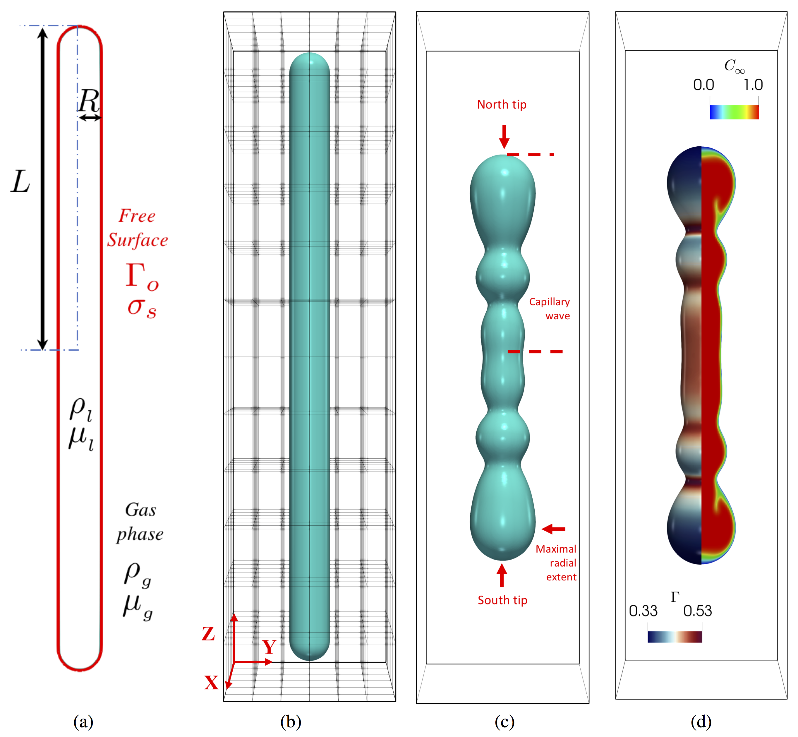
As introduced in the beginning of this section, the liquid ligament is initialised as a cylindrical thread of length with an aspect ratio and hemispherical caps at its two ends, as shown in Fig. 1-(a). The size of the three-dimensional computation domain is where the -coordinate is aligned with the height of the ligament while and are along its width. Hence a radial component is defined as , where and are the abscissa and ordinate ligament position, respectively. The simulation is initialised with fluids at rest in the absence of gravity. A no-slip boundary condition is imposed on the fluid velocity at the walls of the computational domain and a Neumann condition is imposed for the pressure , where n here refers to the normal vector at the boundaries of the computational domain. At the free surface, we set
| (11) |
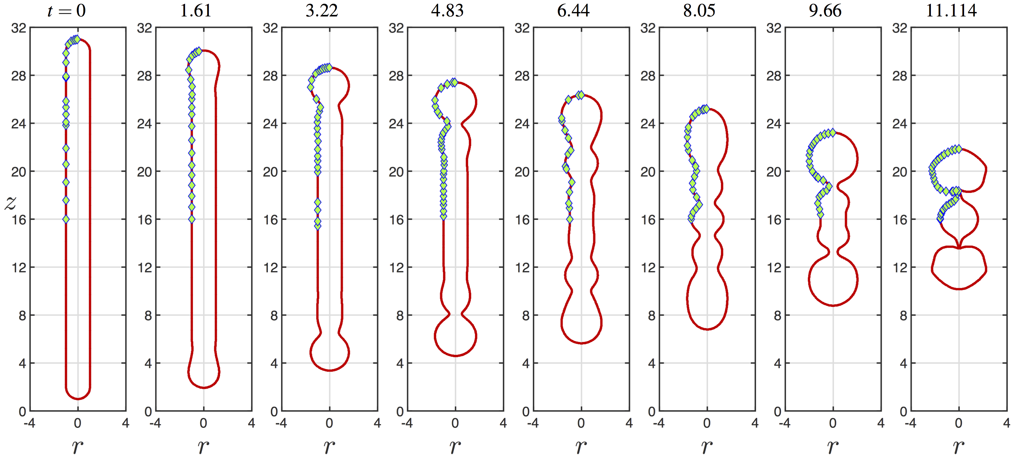
as a condition on . The entire domain is discretised into an Eulerian fixed regular mesh. The surfactant-free simulation was carried out on three different meshes, referred to here as M1, M2, and M3, to ensure mesh-independent results. The results presented in the study correspond to the M2 mesh, unless stated otherwise. The code was benchmarked against the ligament profiles of Notz and Basaran (2004) (see Fig. 2) on the dynamics of the surfactant-free simulation and the pichoff time. The validation of the surfactant solver has been presented previously by Shin et al. (2018), where the authors ensured mass conservation of the surfactant. More information of the validation, mesh refinement studies, and numerical method can be found in the Appendix.
III Results
In this section, we present a discussion of our results, beginning by comparing our predictions with previous work on retracting surfactant-free ligaments. This serves the purpose of validating our numerical method and provides a benchmark against which to highlight the effects associated with the presence of surfactant.
III.1 Surfactant-free ligament retraction and capillary-breakup
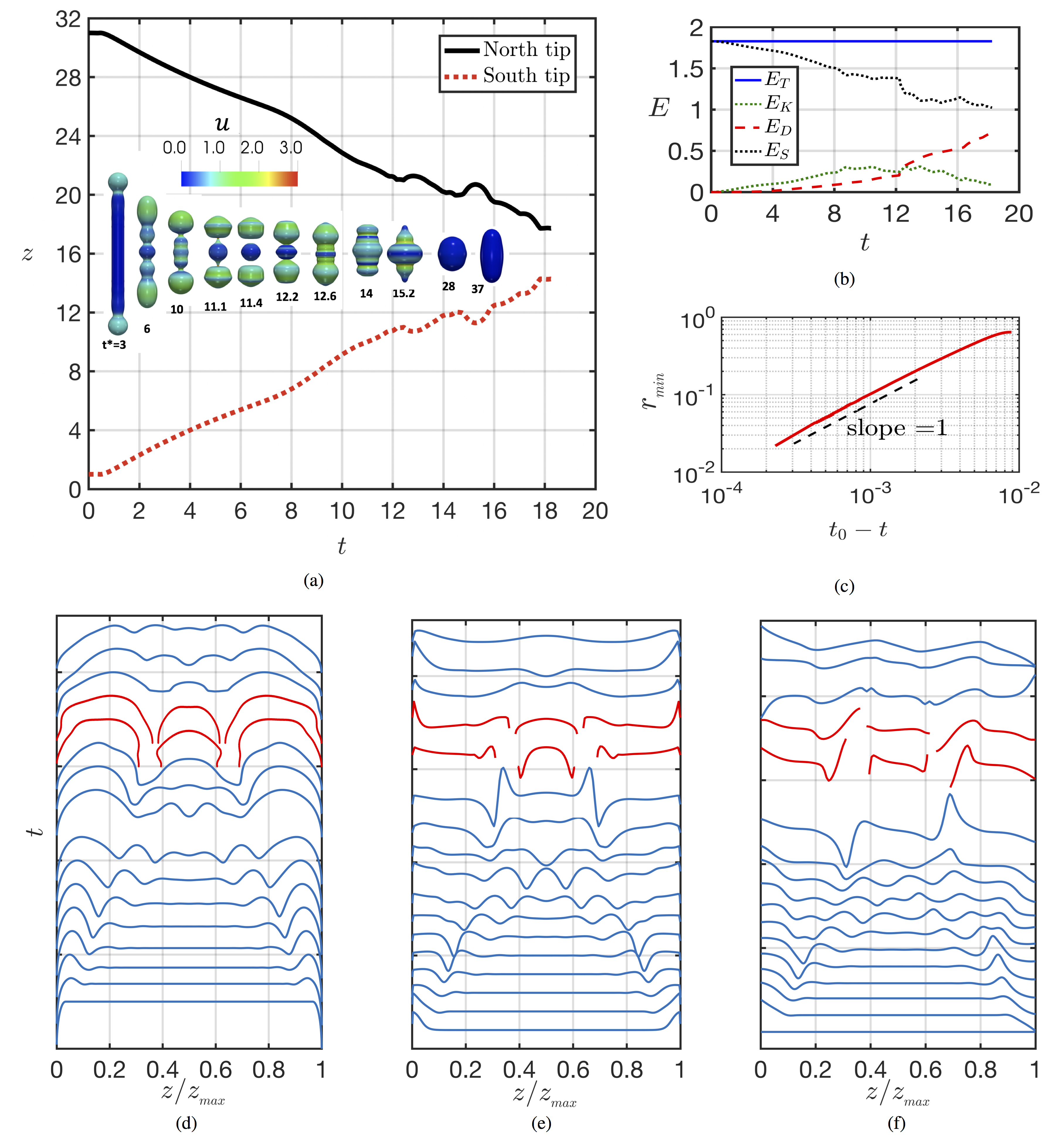
We study the retraction of a surfactant-free ligament with and previously examined by Schulkes (1996) and Notz and Basaran (2004) paying particular attention to interfacial breakup and post-pinchoff dynamics. In order to inspire confidence in the reliability of the numerical method used to carry out the computations, we show in Fig. 2 a comparison between our numerical predictions and those from Notz and Basaran (2004) which reveals a good agreement. Figure 3 depicts time-space plots of the interface, pressure, and the axial velocity; for the latter two, spatial variations are shown with respect to the ligament centreline. The initially motionless, cylindrical ligament undergoes retraction due to the pressure gradient between the two bulbous ends and the rest of its body, which drives flow from these regions towards its centre in the form of a capillary wave; this dominates the early stages of the dynamics.
The retraction velocity results from a force balance between capillary and inertial forces, the latter being proportional to the rate of change of momentum of the bulbous ends. Extending the Taylor-Culick expression for the retraction of a two-dimensional axisymmetric planar liquid sheet to a cylindrical thread, we arrive at , which gives a value for the vertical velocity of retraction m/s. This is in good agreement with the retraction velocity predicted by our simulations, m/s and provides further validation of the accuracy and reliability of our numerical method.
The retraction motion and associated capillary waves form neck regions near the two ends of the ligament connecting the bulbous regions with the rest of the ligament. The pressure under these neck regions is large and drives flow away from them on time scales shorter than those related to retraction, dominating the intermediate stage of the dynamics, and promoting further necking and an even larger pressure gradient that eventually leads to a double pinchoff event for the set of parameters used to generate these results; the profiles for the interface, pressure, and axial velocity associated with this event are highlighted in red in Fig. 3-(d) and (f).
Figure 3-(a), which highlights the temporal evolution of the north and south tips of the bulbous ligament ends during retraction, also shows that the pinchoff, which takes places at , is followed by the formation of three droplets (see Fig. 3-(a) for ). These droplets are sufficiently close that a double coalescence takes place simultaneously at generating capillary waves that travel up and down the ligament (see Fig. 3-(a) for , , and ). These waves decelerate giving way to decaying oscillations between a spherical and an ellipsoidal ligament shape that are the main features of the late-time dynamics (see Fig. 3-(a) for and ).
It is also instructive to perform an analysis of the temporal variation of the system energy. The total energy must be constant over time and its constituents are the surface energy, , where is the superficial area of the ligament, the kinetic energy, , and the energy dissipated, , where refers to a viscous stress tensor. As highlighted in Fig. 3-(b), all energies are normalised by the surface energy of a motionless spherical droplet with a volume similar to that of the ligament of aspect ratio . Initially, the total energy is solely represented by the surface energy . When the ligament retracts, part of the surface energy is transferred into kinetic energy. During the coalescence of the three droplets (at ) the total area of the system changes significantly and a fraction of the surface energy is dissipated (see Fig. 3-(b)). At longer times, and , as the ligament tends towards a steady, spherical shape.
III.2 Surfactant-laden ligament retraction: escape from capillary-breakup
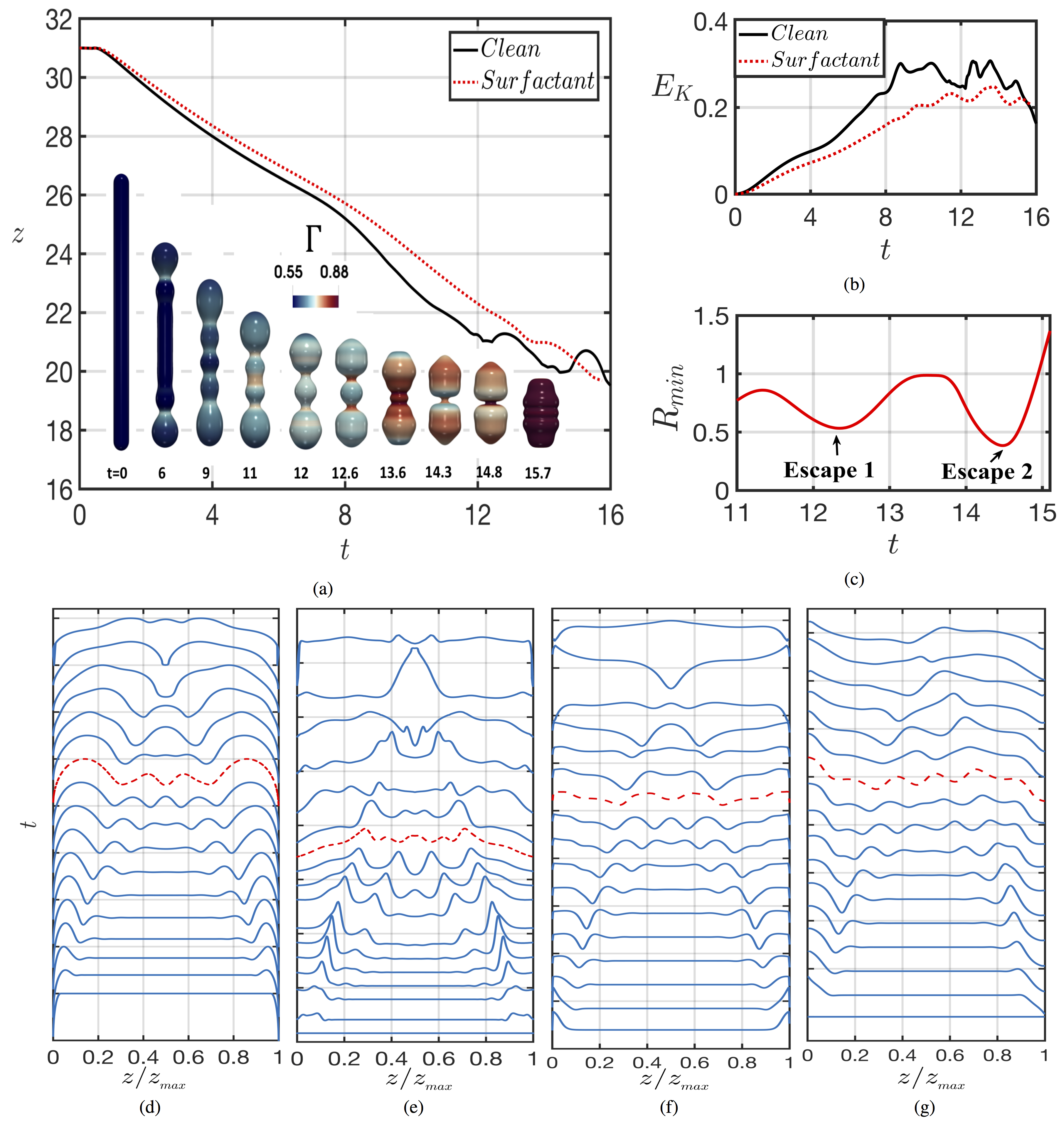
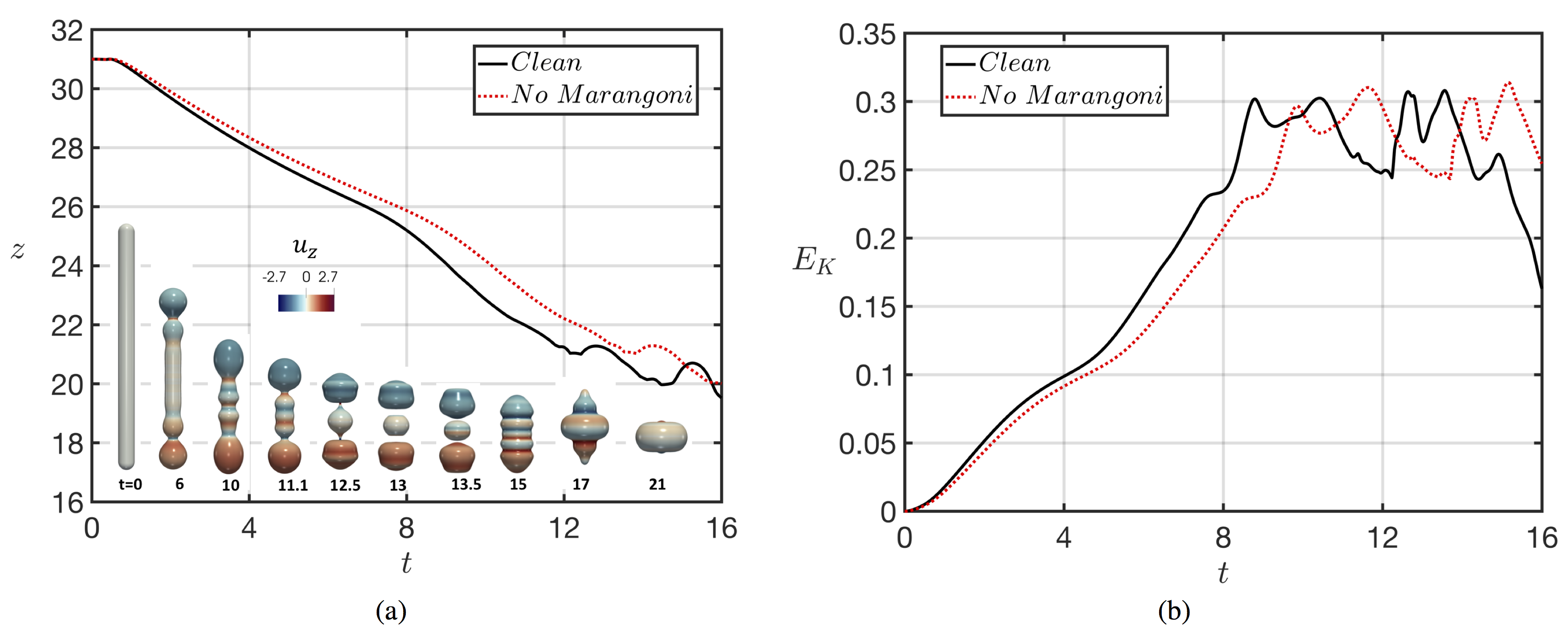
In this section, we present the effect of insoluble surfactant on the dynamics of a retracting ligament with , , , , and . Figure 4 depicts the spatio-temporal evolution of the interface and together with the pressure and axial velocity along the ligament centreline. Similar to the surfactant-free case, retraction is accompanied by the formation of capillary waves that dominate the dynamics leading to the collapse of the initially-cylindrical ligament towards a spherical one. The surfactant concentration , which is coupled to the interfacial dynamics through the dependence of on , is redistributed along the interface, and achieves a maximal value around since the ligament area decreases as it approaches a spherical shape. As shown clearly in Fig. 4-(a) and (b), the presence of surfactant retards ligament retraction as evidenced by the slower temporal evolution of the ligament tips and lower kinetic energy in comparison to the surfactant-free case; the retraction speed is m/s as compared to m/s in the ‘clean’ case. This is due to the surfactant-induced interfacial rigidification brought about by the Marangoni stresses, which, in turn, are caused by gradients in .
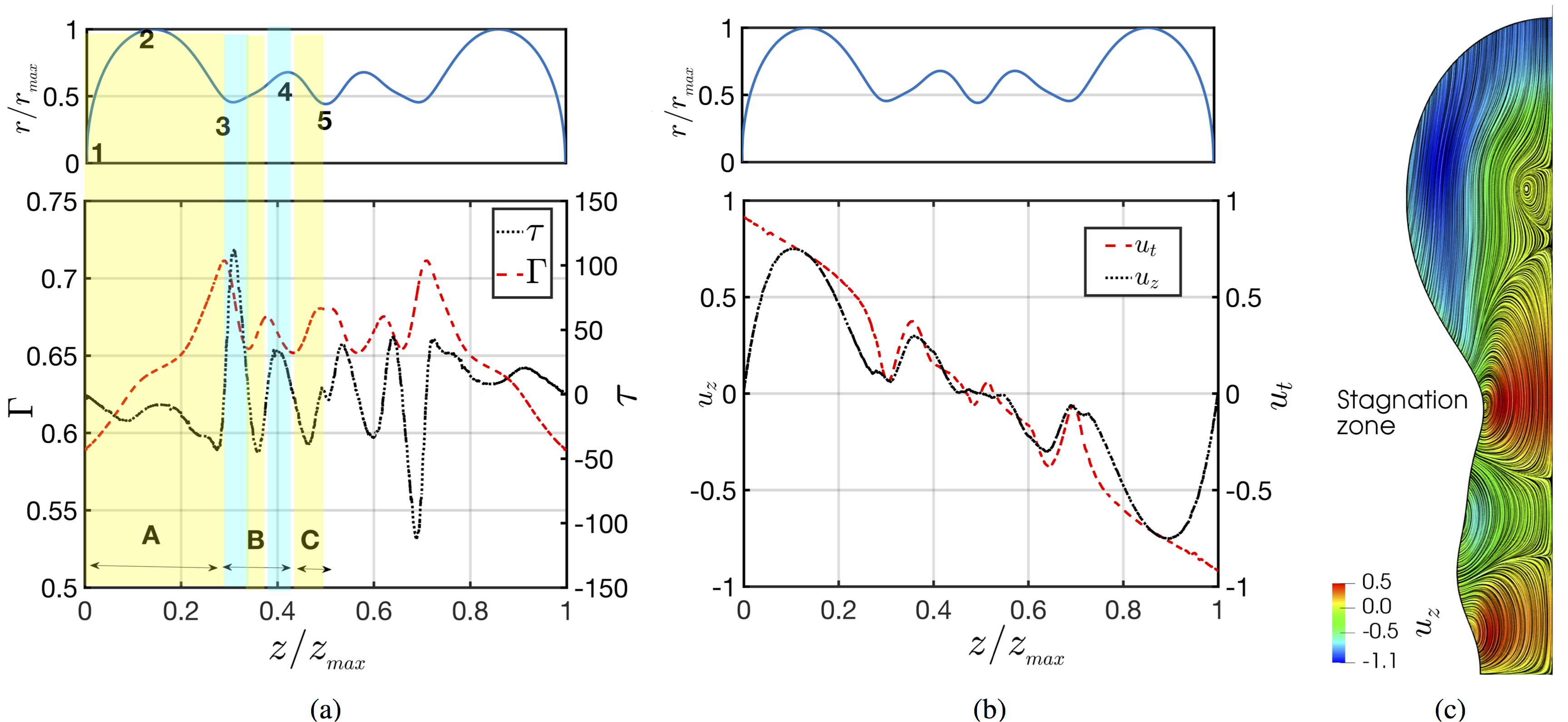
In order to elucidate the coupling between interface and surfactant concentration, we consider the interface, , , and , at shown in red dashed lines in panels (c)-(f) of Fig. 4. The retraction capillary waves are characterised by regions of radially-diverging and converging motion and associated higher and lower interfacial areas and therefore reduced (i.e. increased) and increased (i.e. reduced) () locally, respectively. These concentration gradients lead to Marangoni stresses that drive flow from the higher-tension radially-diverging to the lower-tension converging regions, which act to retard the interfacial motion. To further illustrate the retarding effect of the Marangoni stresses, three distinct regions are also highlighted, as shown in Fig. 5-(a). In Region ‘A’, the interfacial flow diverges away from point ‘1’, at the ligament tip, driving surfactant away from this location leading to the lowest value along the interface. There is an overall increase in from the tip towards the centre reaching a maximal value at location ‘3’ where the interface exhibits a local minimum. The profile then undergoes oscillations in response to the wavy shape of the interface, with a local minimum and maximum in at locations ‘4’ and ‘5’ that coincide with a local interfacial maximum and minimum, respectively. It is clear from Fig. 5-(a) that in Region ‘A’ suggesting that the direction of the Marangoni flow is towards the ligament tip, which acts to retard the capillary-driven flow from the tip towards the centre; this retarding effect in Region ‘A’ manifests itself through a decrease in the tangential velocity along the interface, , as shown in Fig. 5-(b). In Region ‘B’, , thus Marangoni-driven flow is towards the ligament centre, which is counter to the capillary flow away from this necking region. As also indicated in Fig. 5-(b), , which was negative in Region ‘B’ in the surfactant-free, becomes positive in the surfactant-laden case.
It is also evident that using similar mechanisms, the Marangoni-driven flow reduces substantially the magnitude of in Region ‘C’. Figure 5-(c) shows the structure of the streamlines, which characterise the flow within the ligament. It is clearly seen that the formation of several stagnation points occurs along the interface reflecting the competition between the capillary- and Marangoni-driven flows an example of which is provided by the stagnation point close to the neck region. The formation of the stagnation zone is similar to what Kamat et al. (2018) have described, reporting the deceleration of the fluid by the action of the Marangoni stress during the thinning of the fluid thread. This force competition reverses the flow direction, leading to the genesis of the stagnation zone.
In order to separate the effects of mean surface tension and Marangoni stresses induced by surface tension gradients, we consider a case in which the surface tension value is reduced and given by Eq. (7) using the initial interfacial concentration, but where no Marangoni stresses are supported. Figure 6 shows that the reduction in surface tension leads to a delay in the ligament retraction but does not prevent breakup; very similar behaviour to the surfactant-free case is observed in terms of the formation of three droplets, which eventually coalesce, and temporal evolution of the kinetic energy which undergoes a slightly delayed rise due to the slower capillary-driven flow, as expected. These results demonstrate that the prevention of the breakup is due to the formation of Marangoni stresses rather than the reduction in surface tension.
In Fig. 4-(c), we observe two escapes from breakup at and . The interfacial shape prior to the first escape resembles that of the surfactant-free case before its breakup, shown in Fig. 3-(a). Hence, we will compare the flow fields of theses two cases to determine the effect of surfactant on the onset of suppression of the capillary breakup for the surfactant-laden case.
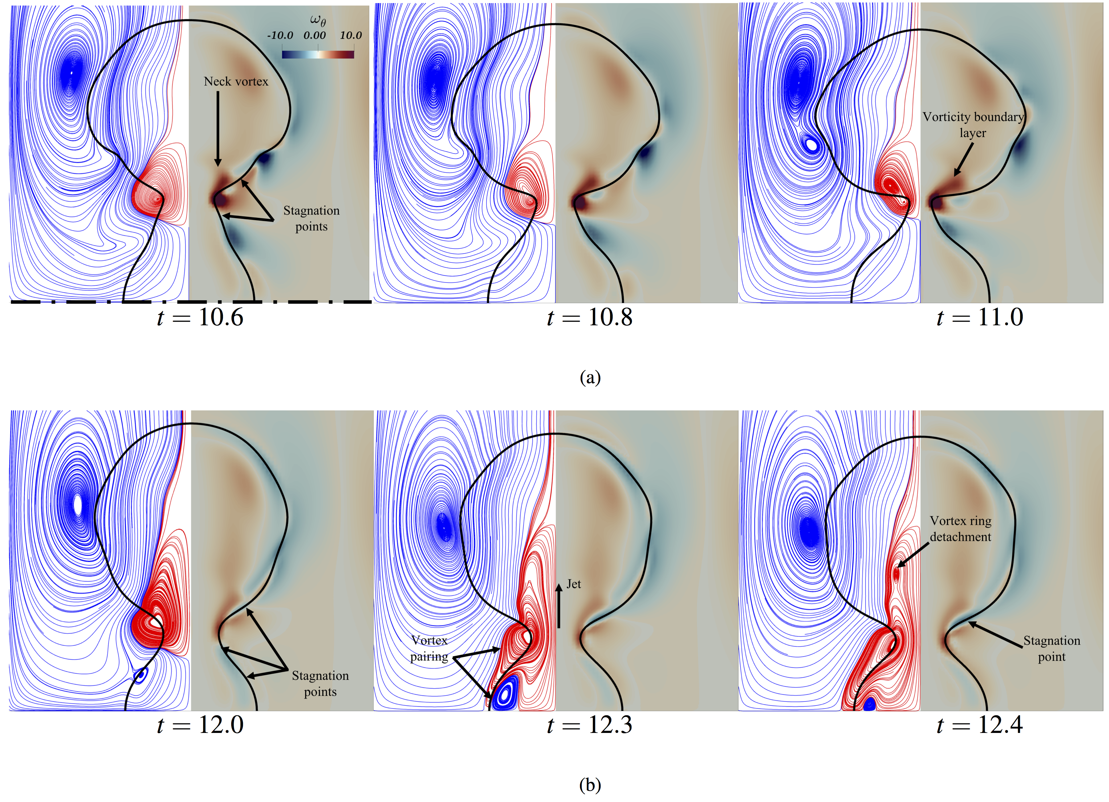
The first row of Fig. 7-(a) shows the flow behaviour through the azimuthal vorticity, , the instantaneous streamlines, and a three-dimensional representation of the velocity vector field for the surfactant-free case before pinchoff. Two stagnation points shown in Fig. 7-(a) at are also observed on either side of the neck, for which there is a change in direction of the flow rotation. By inspecting , the highest vorticity production is located on the neck of the ligament promoted by the large interfacial curvature in that region. A thin vorticity boundary layer is detached from the neck of the ligament and diffuses into the bulk of the bulbous region (see Fig. 7-(a) at ). As the interfacial singularity is approached, the axial velocity component through the neck increases due to the associated rise in the capillary pressure, which pumps liquid rapidly away from the neck towards the bulbous region. The velocity achieves its maximum value at the moment of singularity as can be seen in Fig. 7-(a).
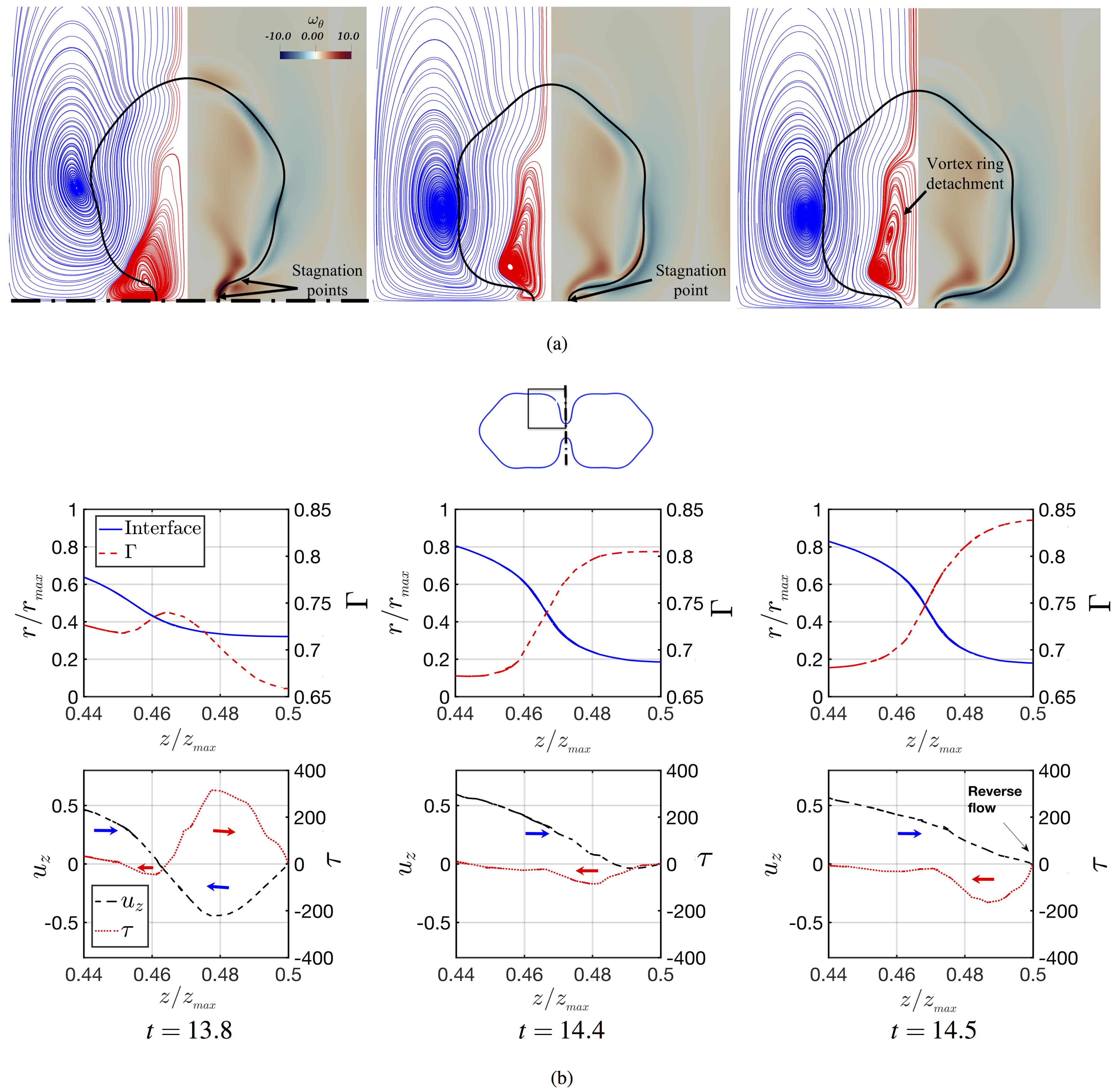
The second row of Fig. 7-(b) shows the flow behaviour for the surfactant-laden case prior to the first escape from pinchoff. Inspection of reveals the formation of a vortex ring also located at the neck, as shown at . However, the vorticity production is not as strong as in the surfactant-free case due to the rigidification of the interface brought about by the presence of Marangoni stresses. In comparison to the surfactant-free case, an additional stagnation point between the neck and the center of the ligament is observed as shown in Fig. 7-(b) at . The presence of this stagnation point has an associated vortex ring which interacts with the interface. As time increases, the mutual interaction of the two vortices leads to a vortex-pairing process, as shown at . This pairing up reverses the flow direction towards the neck ultimately leading to its reopening. The framed regions of the ligament show a magnified view of the flow direction and the flow reversal towards the neck. As the flow re-enters through the neck, the formation of a jet towards the bulbous region is observed, which gives rise to a vortex ring that eventually detaches towards the centre of the bulbous region, as shown at . This behaviour is similar to the phenomenon explained by Hoepffner and Paré (2013) (see their Fig. 6) where they showed that the formation of a vortex ring plays the primary role in the escape from breakup of viscous ligaments in the absence of surfactant.
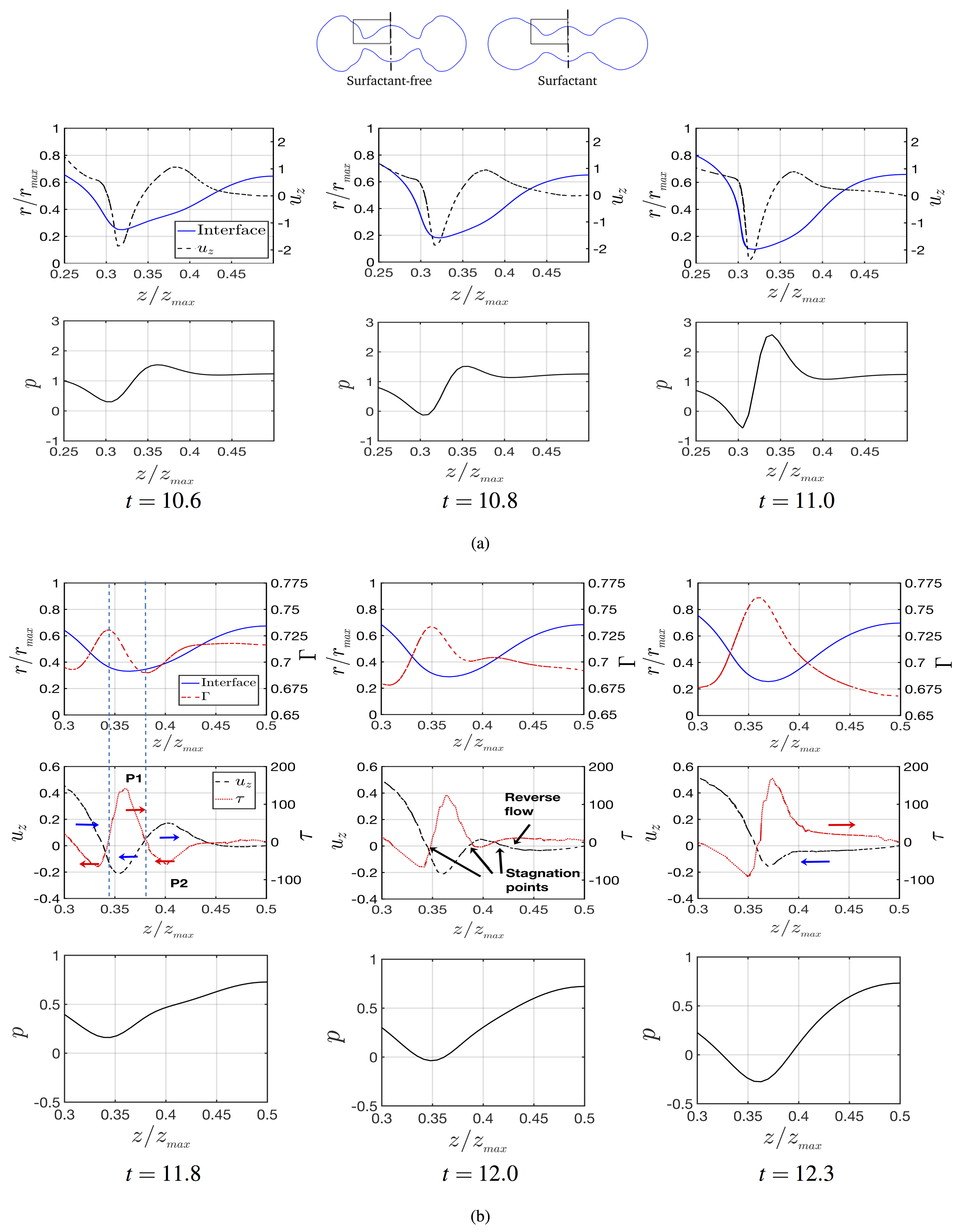
Figure 8-(a) shows the coupling between the interface, , and for the surfactant-free case as the neck evolves towards its capillary breakup. We have limited the fields to the framed region shown at the top of Fig. 8, due to the axisymmetric behaviour of the system. As the neck reduces its size, capillary pressure drives the flow, pumping fluid towards the neck, and, consequently, increases over time.
Similarly, Fig. 8-(b) shows the coupling between , , , and the interface for the surfactant-laden base case. At , has a qualitatively similar behaviour to that associated with the surfactant-free case though the competition between Marangoni stresses and the capillary pressure determines the direction of the flow. Inspection of at reveals the presence of two Marangoni peaks of opposite sign is observed; we have labelled the positive and negative peaks ‘P1’ and ‘P2’, respectively. We have also labelled with red and blue arrows the direction associated with Marangoni-induced and capillary-driven flow.
In the region where P2 is located (see Fig. 8-(b) at ), Marangoni stresses and capillary pressure drive flow towards the neck and the centre of the ligament, respectively. Hence, both mechanisms act in opposing directions. The induced decelerates the flow caused by the capillary pressure (observe that at and is equal to and , respectively). At , an additional stagnation point appears, as already discussed in connection with Fig. 7-(b) and the deceleration continues until flow-reversal occurs at with the merging of two stagnation points. Furthermore, the peak P1 also decelerates the flow which passes through the neck though the neck size reduces over time in this case. After this point, the flow behaviour follows that described previously in the discussion of Fig. 7-(b). It is also noteworthy that a comparison of the pressure for the clean and surfactant-laden cases reveals that a reduction of the capillary pressure is observed in the latter case due to the reduction in surface tension.
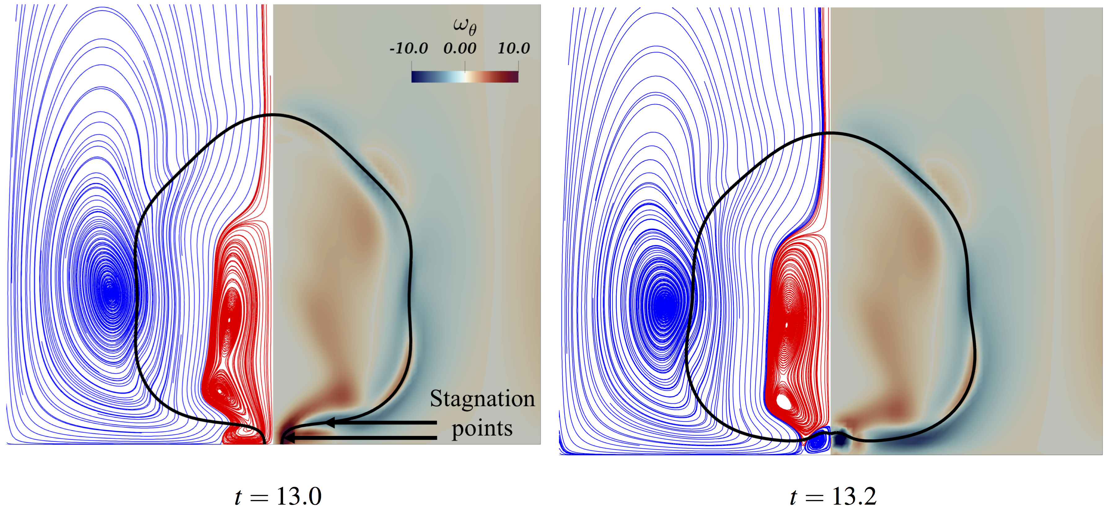
Finally, we examine the flow field associated with the second reopening of the neck, , depicted in Fig. 4-(c). As shown at in Fig. 9, a large counter-clockwise rotating vortex is located at the neck, which drives flow from the neck towards the centre of the bulbous region as shown through the representation of the velocity vector fields. At , the displacement of the vortical ring from the neck towards the bulk is observed. This vortex moves flow from the neck to the bulk triggering the reopening of the neck. Comparing the neck size at , the neck does not stretch further and resists capillary breakup.
Figure 9 shows simultaneously a snapshot of the interface, , and at in which two stagnation points are observed; the highest value of is located close to the neck that links the neck with the bulbous region while its lowest value is at the centre of the ligament. Subsequently, Marangoni stresses induce flow towards the second stagnation point (see the strong magnitude peak of ; a red arrow has been added to highlight the induced flow due to the concentration gradients). In this region, the flow induced by competes with that driven by the capillary pressure in the opposite direction (shown with the blue arrow). As time evolves, is convected towards the centre of the ligament which becomes a point of convergence and acts to oppose the surfactant accumulation (see and ); decelerates the flow induced by the capillary pressure and triggers flow-reversal, which is highlighted by the merging of the two stagnation points at . The flow reversal is due to the decrease in magnitude of the capillary pressure because of the surfactant-induced local reduction in surface tension; consequently, the capillary-driven flow is not strong enough to overcome that due to Marangoni stresses. With the suppression of one of the stagnation points, the vortex ring is displaced towards the bulk of the bulbous region.
III.3 Parametric study
Here, we investigate the fate of the ligament on system parameters such as the dimensionless elasticity parameter, , the surface Peclet number, , the Biot number, , and the adsorption parameter, . Unless stated otherwise, the parameters remain fixed to their ‘base’ values: , , , and .
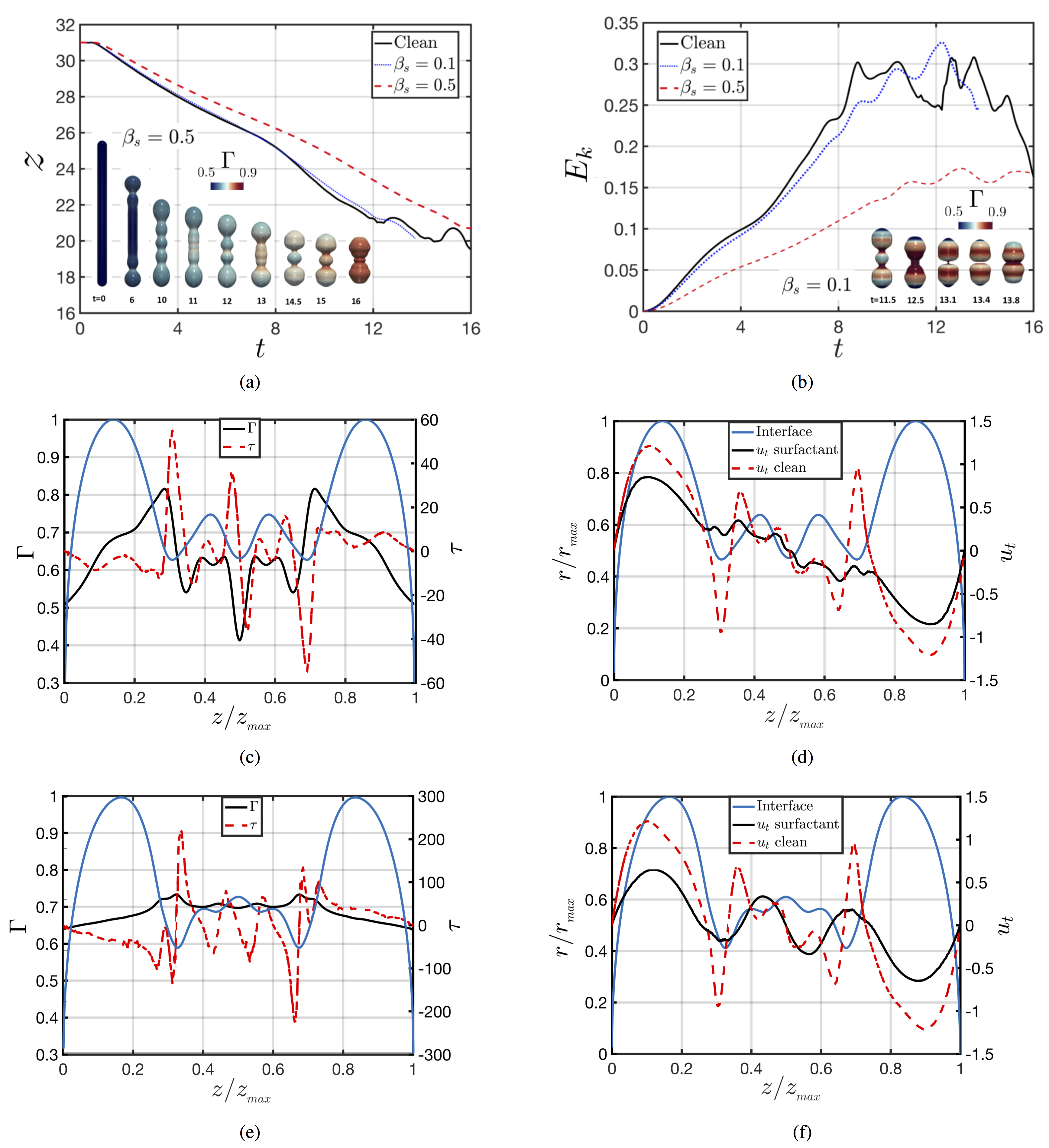
We begin by examining the effect of parameter , which characterises the relative significance of Marangoni stresses. As highlighted above, the redistribution of surfactant along the interface gives rise to concentration gradients and Marangoni stresses that act to retard retraction and prevent ligament pinchoff. Further evidence for this is provided in Fig. 10(a)-(b) in which we plot the temporal evolution of the ligament tip location, and the kinetic energy, respectively, for and . In Fig. 10, we also show a three-dimensional representation of the interface for these values. With increasing , the Marangoni stresses are strengthened leading to a larger reduction in the retraction velocity and highlighting their retarding effect on the dynamics. As can also be seen clearly from Fig. 10(a)-(b), for sufficiently large values, Marangoni stresses dominate the flow preventing ligament breakup. In panels (c) and (e), and (d) and (f) of Fig. 10, in which we plot a snapshot of the interfacial shape, , and (for the clean and surfactant-laden cases), for and 0.5, respectively, it is shown that for the higher value, the larger Marangoni stresses lead to a more uniform distribution of surfactant along the interface and a greater degree of interfacial rigidification; this is illustrated further through the overall reduction in and (see Fig. 10-(b)) with increasing .
For , the escape from the end-pinching mechanism is observed as described in the previous section. For , however, the relative importance of Marangoni stresses is smaller (see magnitude on Fig. 10-(c) which does not lead to prevention of the capillary breakup of the ligament (see interface at . Figure 11 shows that is not sufficiently large to reverse the flow and the merging of the stagnation points does not occur here. Due to the existence of these two stagnation points close to the neck, the vortex ring close to the neck is not displaced towards the bulk (similar to Fig. 9 at ), which is the genesis of the escape of pinchoff. Therefore, we are identifying two different regimes with respect to , and the transition region between the two regimes is located between and .
In Fig. 12, we show the effect of varying , which reflects the influence of surfactant diffusion effects along the interface, on the retraction dynamics. Inspection of this figure reveals that the promotion of diffusive effects through a decrease in leads to a more uniform interfacial distribution of and a reduction in the magnitude of surface tension gradients. It can also be seen that the retraction speed and ligament kinetic energy are weakly-dependent on : they exhibit quantitatively similar dynamics over a three orders of magnitude variation in . Therefore, keeping the other parameters fixed, the inhibition of the end-pinching mechanism (see 12-(a) at ) is expected for cases when .
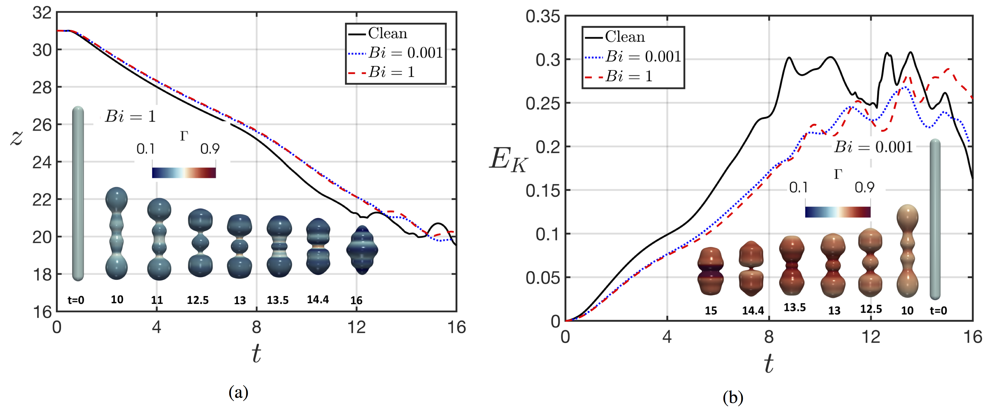
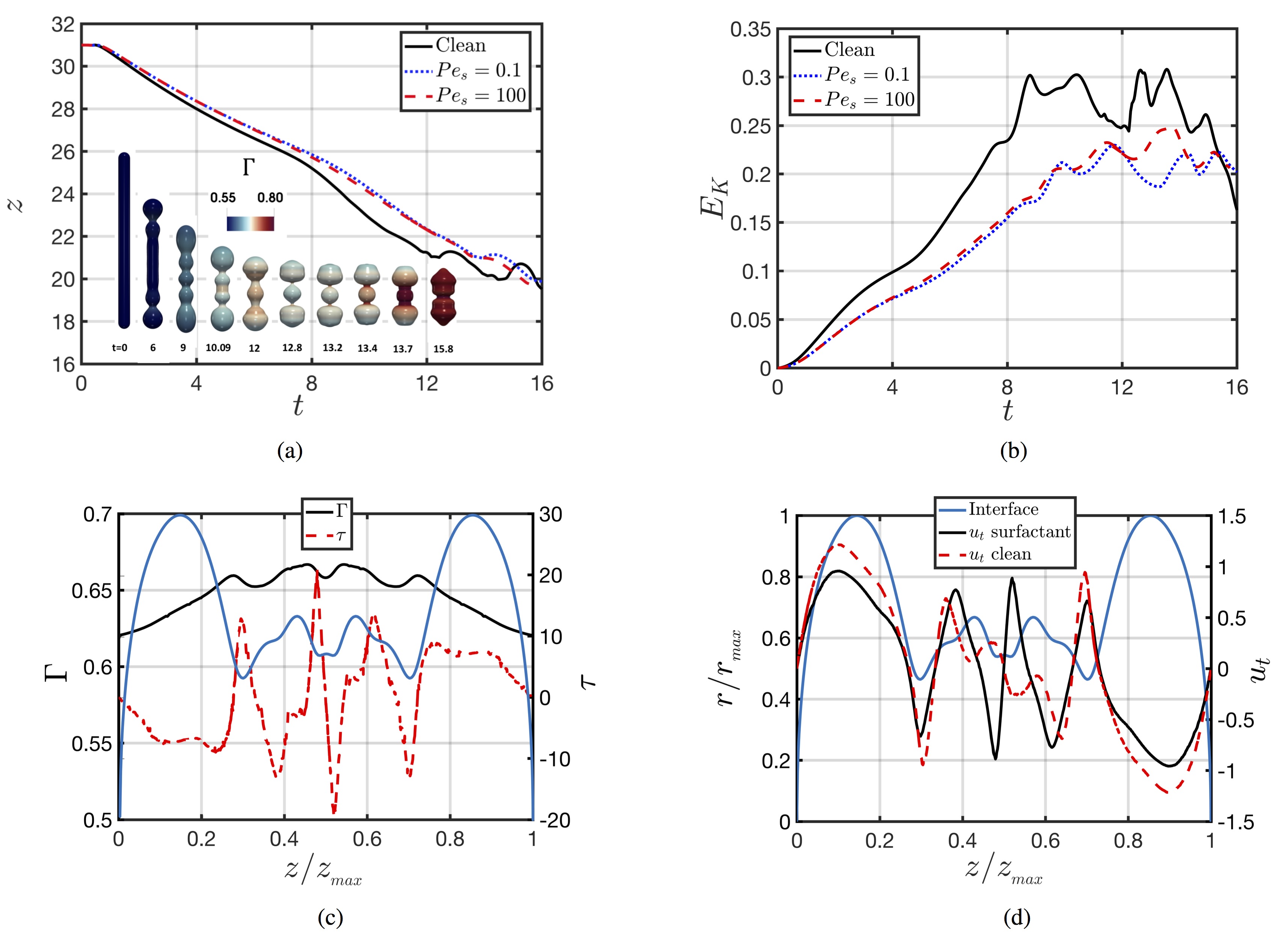
Up to this point, we have only analysed the fate of the ligament in presence of insoluble surfactants; here, we investigate the effect of surfactant solubility on the dynamics by fixing value of the fractional coverage to and exploring the range . At the lower end of this range, the sorptive time scales are much larger than those associated with interfacial effects; consequently, the dynamics are dominated by capillarity and Marangoni stresses and are expected to be similar to those observed in the insoluble surfactant case. For , the sorptive time scales are comparable to their capillary and Marangoni counterparts and the flow will reflect the delicate interplay amongst these effects. Inspection of Fig. 13-(a) and (b), however, shows that, contrary to expectations, has a relatively minor effect on the retraction speed and the ligament kinetic energy. From the three-dimensional representations of the interface, it can be seen that the ligament escapes its breakup for all . For , we observe the escape from breakup at and . The radius of the neck prior to its escape also increases with . Therefore, keeping the other parameters the same, the inhibition of the end-pinching mechanism (e.g. see 13-(a) at ) is observed for three orders of magnitude of .
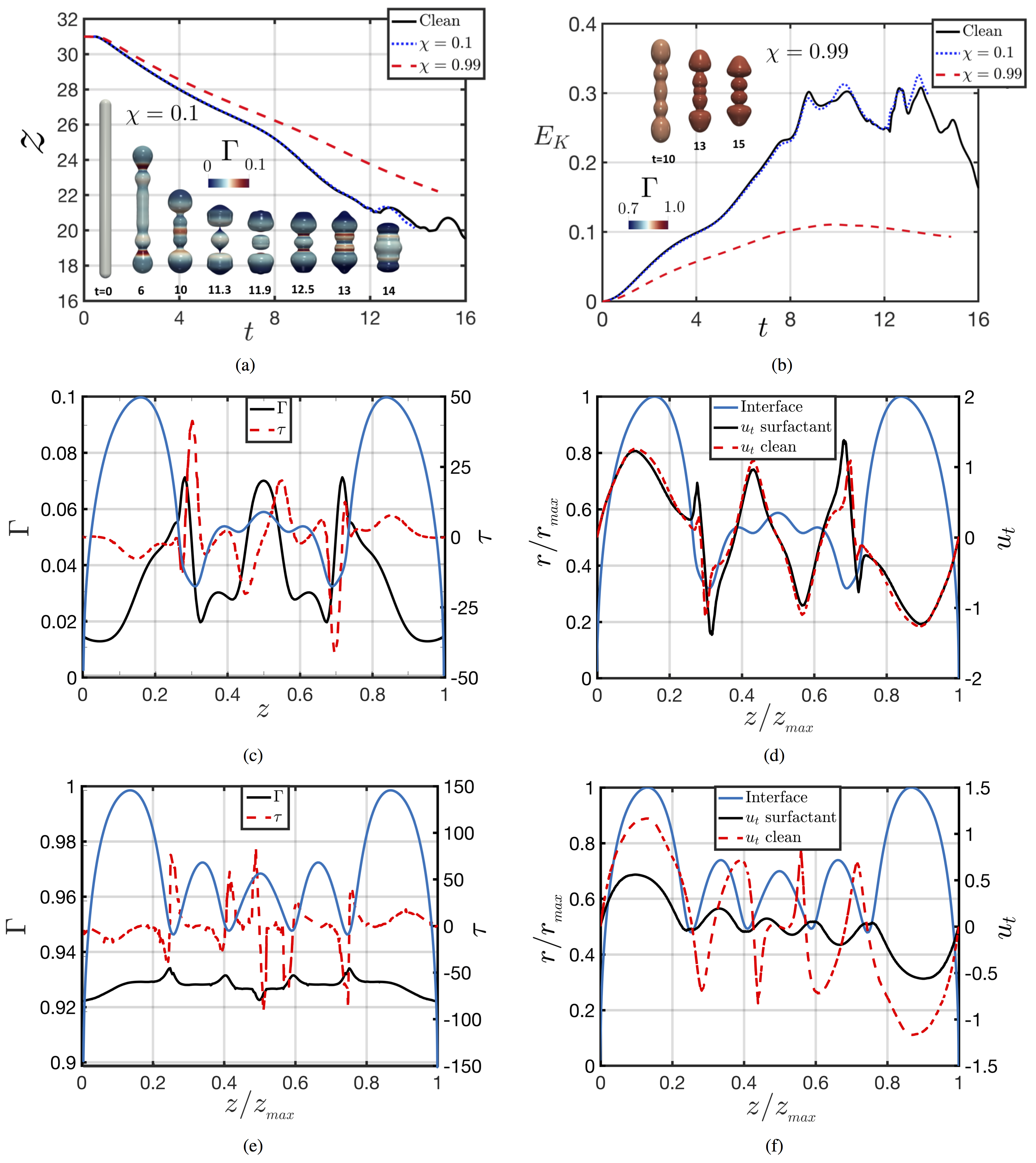
We now investigate the effect of the fractional coverage, represented by on the dynamics with and the rest of the parameters set to their base values. Fig. 14-(a) and (b) shows that whereas the low dynamics resemble that of the surfactant-free case, at high , for which adsorption effects are dominant, a significant reduction in the retraction velocity and kinetic energy is observed. Furthermore, as can be seen in Fig. 14-(c) and (f), for large , interfacial gradients of the surfactant concentration, and therefore of surface tension, are small, which implies that Marangoni stresses play a minor role in this case. Thus, the reduction in ligament retraction velocity must be related to the significant reduction in surface tension, which acts to diminish the magnitude of capillary effects. Therefore, for a low , the relative importance of Marangoni stresses is very small (see magnitude in Fig. 14-c) which does not lead to the prevention of capillary breakup (see interface at .
IV Conclusions
We have presented the effect of surfactant on ligament retraction of an aspect ratio and for intermediate Ohnersorge numbers, . We have performed fully three-dimensional numerical simulations of the retracting process over a range of system parameters that account for the surfactant solubility and sorption kinetics and Marangoni stresses. The numerical method has been validated against the work of Notz and Basaran (2004) for a surfactant-free case. Our results indicate that the presence of surfactant inhibits the end-pinching mechanism and promotes the neck re-opening through Marangoni-flow, induced by the formation of surfactant concentration gradients, and not via lowering of the mean surface tension. The induced Marangoni stresses decelerate the flow caused by the capillary pressure until flow-reversal occurs close to the neck. As the flow re-enters through the neck, the formation of a jet towards the bulbous region is observed, which gives rise to a vortex ring that eventually detaches towards the centre of the bulbous region. This behaviour is similar to the phenomenon explained by Hoepffner and Paré (2013) in the escape from breakup of viscous ligaments in the absence of surfactant. Therefore, the presence of surfactants avoids the ‘end-pinching’ mechanism because of the existence of Marangoni stresses that suppress the mechanism of the Rayleigh-Plateau instability. This inhibition of the flow singularities is a remarkable outcome in the presence of a contaminant. We have also demonstrated that the pinchoff inhibition cannot happen by simply reducing the value of the surface tension, but only by the introduction of the Marangoni stresses. The presence of Marangoni stresses also leads to interfacial rigidification, which is observed through reduction of the ligament retraction velocity and the ligament kinetic energy. We have also investigated how the variation of key surfactant parameters affects the fate of the ligament. At , Marangoni stresses are insufficiently large to influence the flow close to the neck and do not prevent the capillary breakup of the ligament. We also found that for the whole studied range of and an escape from end-pinching occurred. Additionally, we showed that solubility, contrary to expectations, has a relatively minor effect on the retraction speed and the ligament kinetic energy. Finally, the adsorption effects were studied via variation of , where at , Marangoni stresses do not lead to the prevention of capillary breakup.
This research is of importance for many applications that aim to produce equal-sized droplets, which is a desired outcome for improving efficiency in technologies such as ink-jet printing. An interesting future line of research would be to study the one-dimensional free-surface slender cylindrical flow on the Navier-Stokes equations coupled with a set of equations describing the surfactant interfacial transport on a Newtonian liquid thread. This analysis could provide insights into the relationship between the classic Taylor-Culick retraction velocity and interfacial rigidification brought by the surface-active agents. Future research avenues involve performing numerical simulations of curved ligaments to breakup the symmetry behaviour and of non-Newtonian ligaments, including visco-plastic and visco-elastic types, with a large range of Ohnesorge numbers and ligament aspect ratios. The retraction dynamics of non-axisymmetric ligaments may lead to the formation of ‘entrapped bubbles’ inside the ligament and a three-dimensional oscillatory dynamics of the formed droplet.
Acknowledgements
This work is supported by the Engineering & Physical Sciences Research Council, United Kingdom, through a studentship for RC-A in the Centre for Doctoral Training on Theory and Simulation of Materials at Imperial College London funded by the EPSRC (EP/L015579/1) (Award reference:1808927), and through the EPSRC MEMPHIS (EP/K003976/1) and PREMIERE (EP/T000414/1) Programme Grants. OKM also acknowledges funding from PETRONAS and the Royal Academy of Engineering for a Research Chair in Multiphase Fluid Dynamics. We also acknowledge the Thomas Young Centre under grant number TYC-101. DJ and JC acknowledge support through computing time at the Institut du Developpement et des Ressources en Informatique Scientifique (IDRIS) of the Centre National de la Recherche Scientifique (CNRS), coordinated by GENCI (Grand Equipement National de Calcul Intensif) Grant 2020 A0082B06721. The numerical simulations were performed with code BLUE (Shin et al. (2017)) and the visualisations have been generated using ParaView.
APPENDIX
Mesh study and numerical method
Filament profiles (characterised by and ) are compared against Notz and Basaran (2004), from which data was extracted by image analysis. They used a Galerkin finite element approach under a two-dimensional axisymmetric assumption in the azimuthal direction. As shown in Fig. 2, the ligament profiles show a good qualitative agreement with our numerical method. The second check that we are performing is the predicted time for the capillary breakup for the surfactant-free case between the two methods (Notz and Basaran’s pinchoff time is 11.114 and our pinchoff time for different meshes are shown in Table I), which shows a good quantitative agreement between the two methods. These two checks allow us to proceed with caution.
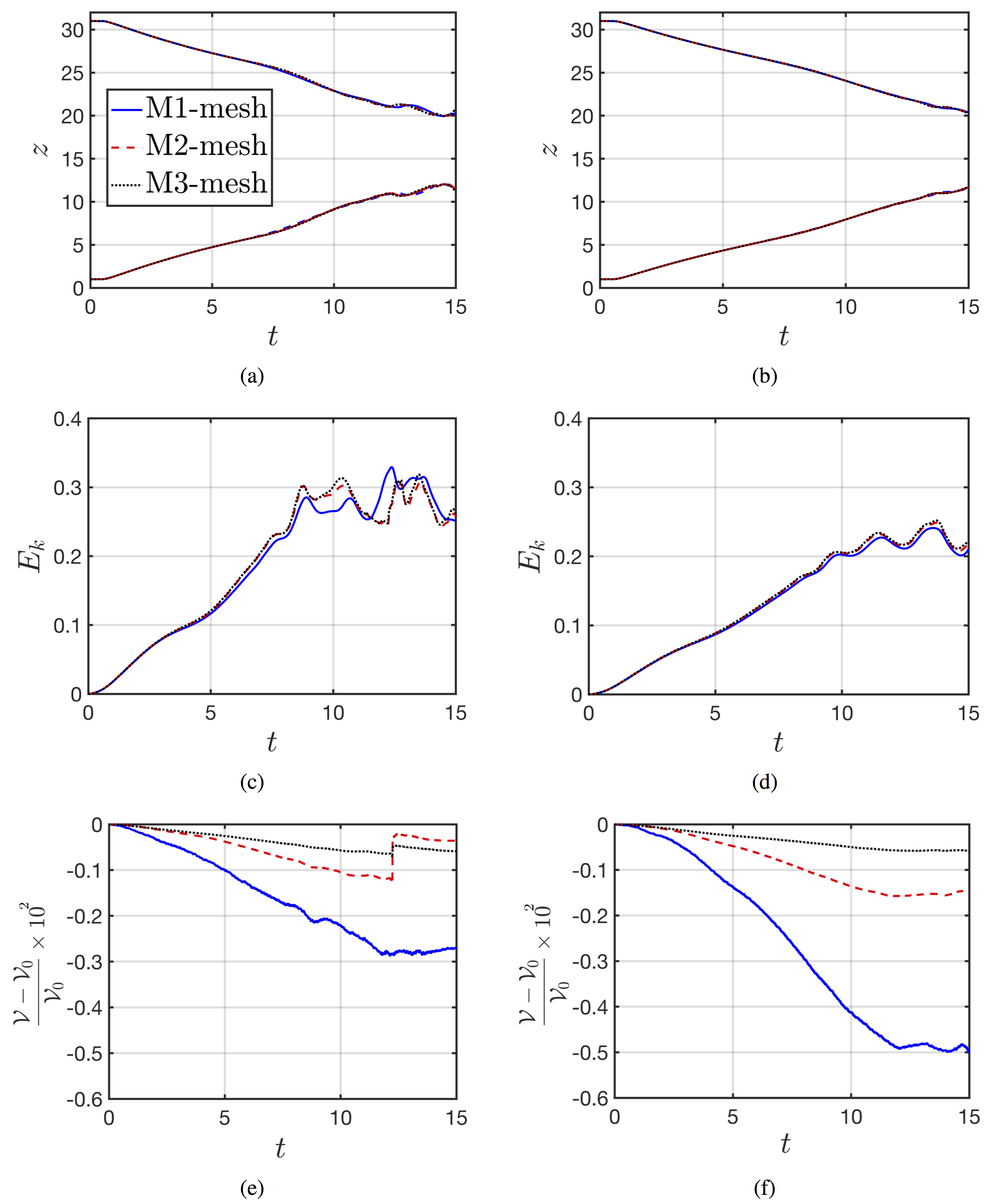
The next question is to ensure that our numerical results are mesh-independent. To this end, the dynamics of the retracting ligament for the surfactant free (i.e., and ) and surfactant laden base cases (i.e., , , and ) are tested for different mesh resolutions (see Fig. 15) in terms of the temporal evolution of the tips location, and the relative variation of the liquid volume. The main characteristics of the meshes are summarised in Table 1 including the number of elements, and the predicted pinchoff time for the surfactant-free case. As for the time , the resulting three droplets coalesce with each other to form a single droplet (shown in Fig. 15-a). The volume of the liquid is conserved with a loss of less than during the topological changes. Because the curves for the kinetic energy and the location of the tips overlap for M2 and M3 meshes, we conclude that M2 is sufficiently refined to ensure mesh-independent results while providing a good compromise with the computational cost of the simulation. The results presented in this paper correspond to the M2 mesh. Additionally, We have carefully checked the accuracy of the surfactant mass conservation in all our simulations. Our numerical framework conserves surfactant moles with a relative error of for the surfactant-laden base case. Moreover, the code conserves surfactant moles with a relative error of (for case: , , , , , and ).
| Run |
|
|
|
||||||
|---|---|---|---|---|---|---|---|---|---|
| M1 | |||||||||
| M2 | |||||||||
| M3 |
The temporal integration scheme is based on a second-order Gear method (Trucker (2013)), with implicit solution of the viscous terms of the velocity components. Each time step is computed by an adaptive time step-size criterion:
| (12) |
where and represent the capillary time step, the viscous time step, the Courant- Friedrichs-Lewy (CFL) time step, and interfacial CFL time step, respectively. Those terms are defined by
| (13) |
where refers to the minimum cell size, and are the maximum fluid and interface velocities, respectively. More details of the numerical method are provided in Shin et al. (2018, 2017). A brief summary of the numerical aspects that are relevant to the study is presented here. The Navier Stokes equations are solved by a finite volume method on a staggered grid (Harlow and Welch (1965)). The computational domain is discretised by a fixed regular grid (i.e. Eulerian grid) and the spatial derivatives are approximated by standard centred difference discretisation, except for the non-linear term, which makes use of a second-order essentially non-oscillatory (ENO) scheme Shu and Oshe (1989); Sussman et al. (1998). In the case of the viscous term, a second-order centred difference scheme is used. The projection method is used to treat the incompressibility condition Chorin (1968). A multigrid iterative method is used for solving the elliptic pressure Poisson equation
With respect to the treatment of the free surface. The interface is tracked with an additional Lagrangian grid by using the Front-Tracking method together with the reconstruction of the interface by using the Level Contour Reconstruction Method Shin and Juric (2002, 2009). Communication between the Eulerian and Lagrangian grid (for the transfer of the geometric information of the interface) is done by using the discrete delta function and the immersed boundary method of Peskin (1977). The advection of the Lagrangian interface is done by integrating with a second-order Runge-Kutta method, where V stands for the interfacial velocity which has been calculated by interpolation from the Eulerian velocity. The code is parallelised through an algebraic domain-decomposition technique and the communication between subdomains for data exchange is managed by the Message Passing Interface (MPI) protocol. Figure 1-(b) highlights the partitioning of the computational domain into sub-domains.
Finally, due to the nature of the system, the surfactant transport is solved on the interface, where the surfactant concentration is located on the centre of the triangular front elements. In the convective-diffusive equations, the time is integrated by a first order explicit scheme. The surface surfactant gradients in the interface are computed by using a probing technique introduced by Udaykumar et al. (1999). A Sharp boundary condition for bulk surfactant concentration equation is implemented to treat the source term at the interface.
References
- Anthony et al. (2019) C. R. Anthony, P. M. Kamat, M. T. Harris, and O. A. Basaran, Dynamics of contracting filaments, Phys. Rev. Fluids, 4, 093601 (2019).
- Basran (2002) O. A. Basaran, Small-scale free surface flows with breakup: Drop formation and emerging applications, AIChE Journal, 48(9), 1842–1848 (2002)
- Bleys and Joos (1985) G. Bleys and P. Joos, Adsorption kinetics of bolaform surfactants at the air/water interface, J. Phys. Chem., 89(6) 1027–1032 (1985).
- Castrejón-Pita et al. (2012) A. A. Castrejón-Pita, J. R. Castrejón-Pita, and I. M. Hutchings, Breakup of Liquid Filaments, Phys. Rev. Lett., 108, 074506 (2012)
- Castrejón-Pita et al. (2015) J. R. Castrejón-Pita, A. A. Castrejón-Pita, S. S. Thete, K. Sambath, I. M. Hutchings, J. Hinch, J. R. Lister, and O. A. Basaran Plethora of transitions during breakup of liquid filaments, PNAS, 112 (15), 4582–4587 (2015)
- Chorin (1968) J. Chorin, Numerical solution of the Navier-Stokes equations, Math. Comp., 22, 745-762 (1968)
- Contó et al. (2019) F. P. Contó, J. F. Marín, A. Antkowiak, J. R. Castrejón-Pita and L. Gordillo, Shape of a recoiling liquid filament, Scientific Reports, 9, 15488 (2019)
- Craster et al. (2002) R. V. Craster, O. K. Matar, and D. T. Papageorgiou, Pinchoff and satellite formation in surfactant covered viscous threads, Phys. Fluids., 14, 1364 (2002)
- Craster et al. (2009) R. V. Craster, O. K. Matar, and D. T. Papageorgiou, Breakup of surfactant-laden jets above the critical micelle concentration, J. Fluid Mech., 629, 195–219 (2009)
- Day et al. (1998) R. Day, E. Hinch, and J. Lister, Self-Similar Capillary Pinchoff of an Inviscid Fluid, Phys. Rev. Lett., 80(4), 704–707 (1998)
- Eggers (1993) J. Eggers, Universal pinching of 3D axisymmetric free-surface flow, Phys. Rev. Lett., 71(21), 3458–3460 (1993)
- Eggers (1997) J. Eggers, Nonlinear dynamics and breakup of free-surface flows, Rev. Mod. Phys., 69(3), 865–930 (1997)
- Eggers and Villermaux (2008) J. Eggers, and E. Villermaux Physics of liquid jets, Rep. Prog. Phys., 71, 036601 (2008)
- Harlow and Welch (1965) F. H. Harlow and J. E. Welch, Numerical calculation of time dependent viscous incompressible flow of fluid with free surface, Phys. Fluids, 8, 2182-2189 (1965).
- Hoath et al. (2013) S. D. Hoath, S. Jung, and I. M. Hutchings A simple criterion for filament break-up in drop-on-demand inkjet printing, Phys. Fluids., 25, 021701 (2013)
- Hoepffner and Paré (2013) J. Hoepffner and G. Paré Recoil of a liquid filament: escape from pinch-off through creation of a vortex ring, J. Fluid Mech., 734, 183–197 (2013)
- Jin et al. (2006) F. Jin, N. R. Gupta, and K. J. Stebe, The detachment of a viscous drop in a viscous solution in the presence of a soluble surfactant, Phys. Fluids., 18, 022103 (2006)
- Jin and Stebe (2007) F. Jin and K. J. Stebe, The effects of a diffusion controlled surfactant on a viscous drop injected into a viscous medium, Phys. Fluids., 19, 112103 (2007)
- Joos et al. (1982) P. Joos, G. Bleys, and G. Petre, Adsorption kinetics of nonanediol and nonane dicarbonic acid at the air/water interface, J. Chim. Phys., 79, 387–393 (1982)
- Joos and Serrien (1989) P. Joos, and G. Serrien, Adsorption kinetics of lower alkanols at the air/water interface: Effect of structure makers and structure breakers, J. Coll. Int. Sci., 127(1) 97–103 (1989)
- Kamat et al. (2018) P. M. Kamat, B. W. Wagoner, S. S. Thete, and O. A. Basaran, Role of Marangoni stress during breakup of surfactant-covered liquid threads: Reduced rates of thinning and microthread cascades, Phys. Rev. Fluids., 3, 043602, (2018)
- Kovalchuk et al. (2016) N. M. Kovalchuk, E. Nowak, and M. J. H. Simmons, Effect of Soluble Surfactants on the Kinetics of Thinning of Liquid Bridges during Drops Formation and on Size of Satellite Droplets, Langmuir 32, 5069–5077 (2016)
- Kovalchuk et al. (2018) N. M.Kovalchuk, H. Jenkinson, R. Miller, and M. J. H. Simmons, Effect of soluble surfactants on pinch-off of moderately viscous drops and satellite size, J. Coll. Int. Sci. 516, 182–191 (2018)
- Marmottant and Villermaux (2004) P. Marmottant, and E. Villermaux, On spray formation, J. Fluid mech., 498, 73–111, (2004)
- McGough and Basaran (2006) P. T. McGough and O. A. Basaran, Repeated Formation of Fluid Threads in Breakup of a Surfactant-Covered Jet, Phys. Rev. Lett., 96, 054502 (2006)
- Notz and Basaran (2004) P. Notz and O. A. Basaran, Dynamics and breakup of a contracting liquid filament, J. Fluid Mech., 512, 223–256 (2004)
- Liao et al. (2004) Y-C. Liao, Hariprasad J. Subramani, E. I. Franses, and O. A. Basaran, Effects of Soluble Surfactants on the Deformation and Breakup of Stretching Liquid Bridges, Langmuir 20, 9926–9930 (2004)
- Lister and Stone (1998) J. Lister and H. Stone, Capillary breakup of a viscous thread surrounded by another viscous fluid, Phys. Fluids, 10(11), 2758–2764 (1998)
- Peskin (1977) C. S. Peskin, Numerical analysis of blood flow in the heart, J. Comp. Phys. 25 220-252 (1977)
- Plateau (1873) J. A. F. Plateau, Experimental and Theoretical Statics of Liquids Subject to Molecular Forces Only, Gauthier-Villars: Paris (1873)
- Rayleigh (1879) L. Rayleigh, On the capillary phenomena of jets, Proc. London Math. Soc. 29, 71–97 (1879)
- Roché et al. (2009) M. Roché, M. Aytouna, D. Bonn and H. Kellay, Effect of Surface Tension Variations on the Pinch-Off Behavior of Small Fluid Drops in the Presence of Surfactants, Phys. Rev. Lett., 103(26), 264501 (2009)
- Schulkes (1996) R. M. S. M Schulkes, The contraction of liquid filaments, J. Fluid Mech. 309, 277–300 (1996)
- Shin and Juric (2002) S. Shin and D.Juric, Modeling Three-Dimensional Multiphase Flow Using a Level Contour Reconstruction Method for Front Tracking without Connectivity, J. Comp. Phys. 180 427–470 (2002).
- Shin and Juric (2009) S. Shin and D.Juric, A hybrid interface method for three-dimensional multiphase flows based on front-tracking and level set techniques, Int. J. Num. Meth. Fluids 60 753–778 (2009).
- Shin et al. (2017) S. Shin, J. Chergui, and D. Juric, A solver for massively parallel direct numerical simulation of three-dimensional multiphase flows, J. Mech. Sc. Tech., 31, 1739–175 (2017)
- Shin et al. (2018) S. Shin, J. Chergui, D. Juric, L. Kahouadji, O. K. Matar, and R. V. Craster, An Interface-Tracking Technique for Multiphase Flow with Soluble Surfactant, J. Comp. Phys., 359, 409–435 (2018)
- Shu and Oshe (1989) C. Shu and S. Oshe, Efficient implementation of essentially non-oscillatory shock-capturing schemes, II, J. Comp. Phys., 83 (1), 32–78 (1989)
- Sussman et al. (1998) M. Sussman, E. Fatemi, P. Smereka and S. Osher, An improved level set method for incompressible two-phase flows, Comp. Fluids 27 (5), 663-680 (1998)
- Trucker (2013) P. Trucker, Unsteady computational fluid dynamics in aeronautics, Springer, (2013)
- Udaykumar et al. (1999) H. S. Udaykumar, R. Mittal, and W. Shyy, Computation of Solid-Liquid Phase Fronts in the Sharp Interface Limit on Fixed Grids, J. Comp. Phys. 153, 535–574 (1999).
- Wang et al. (2019) F. Wang, F. P. Contò, N. Naz, J. R. Castrejón-Pita, A. A. Castrejón-Pita, C. G. Bailey, W. Wang, J. J. Feng and Y. Sui, A fate-alternating transitional regime in contracting liquid filaments, J. Fluid Mech. 860, 640-653 (2019)