Dynamics of laterally-coupled pairs of spin-VCSELs.
Abstract
A newly-developed normal mode model of laser dynamics in a generalised array of waveguides is applied to extend the spin-flip model (SFM) to pairs of evanescently-coupled spin-VCSELS. The effect of high birefringence is explored, revealing new dynamics and regions of bistability. It is shown that optical switching of the polarisation states of the lasers may be controlled through the optical pump and that, under certain conditions, the polarisation of one laser may be switched by controlling the intensity and polarisation in the other.
I Introduction
Recent years have seen a growth of research interest in the nonlinear dynamics of arrays of vertical cavity surface-emitting lasers (VCSELs) and in potential applications of these effects. Notable advances include work on parity-time symmetry and non-Hermiticity associated with the control of gain and loss in neighbouring VCSEL cavities Gao et al. (2017, 2018, 2019); Dave et al. (2019). Progress has also been rapid in the understanding of ultrahigh-speed resonances that offer the prospect of very high frequency modulation of coupled VCSELs and nanolasers Fryslie et al. (2017); Xiao et al. (2017); Han and Shore (2018); Kominis et al. (2019). Additional insight into optical coupling between adjacent elements of a two-dimensional VCSEL array has been achieved by careful analysis of the effects of varying the injected current independently on each array element Pan et al. (2018a). The coupling was shown to provide extra optical gain for array elements and thus lead to additional output power of the array due to in-phase operation Pan et al. (2018a, b), reduced thresholds of individual elements Pan et al. (2018a, 2019) and even cause unpumped elements to lase Pan et al. (2018a).
In almost all the above examples of recent progress, modelling of the array behaviour based on coupled mode theory (CMT) has been used to explain experimental results and develop improved understanding of fundamental effects. Conventional CMT describes only the amplitude and phase of the electric field of the photons and the total concentration of the electrons. Whilst this is adequate for modelling many phenomena occurring in laser arrays, it cannot easily be adapted to include the effects of optical polarisation or electron spin that are often relevant in vertical cavity lasers. For this purpose, the spin flip model (SFM) San Miguel et al. (1995) is well-established as the method of choice, and has been successfully extended to model mutually coupled VCSELs by adding delayed optical injection terms Vicente et al. (2006). This approach has been successfully applied recently to proposed applications of mutually coupled VCSELs in secure key distribution based on chaos synchronization Jiang et al. (2017) and reservoir computing based on polarization dynamics Guo et al. (2019).
Spin-VCSELs, where the polarisation and dynamics can be controlled by the injection of spin-polarised carriers, have recently attracted considerable attention since very high-speed (200 GHz) modulation has been demonstrated Lindemann et al. (2019) by applying mechanical stress to increase the birefringence. In the present contribution we explore some of the dynamics predicted for coupled pairs of spin-VCSELs based on a newly-developed theoretical treatment Vaughan et al. (2019a) that extends the SFM to apply to VCSEL arrays. This approach, which uses normal modes rather than CMT, accounts accurately for instantaneous coupling via evanescent fields or leaky waves. It is therefore able to model the details of the optical guidance in the spin-VCSELs and effects of varying the spacing between them, thus going beyond the description offered by adding optical injection terms to the conventional SFM. The next section gives a brief summary of this treatment leading to a set of rate equations. Subsequent sections deal with results, discussion and conclusions.
II Double-guided structure
In Ref. Vaughan et al. (2019a), a general set of rate equations for any number of coupled lasers with an arbitrary waveguide geometry and any number of optical modes, including the polarisation was derived from Maxwell’s equations and the optical Bloch equations. In this model, the geometry of the waveguides is introduced through the introduction of overlap factors, defined by
| (1) |
where and label the modes, is the spatial profile of the th mode and the integral is over the th guide. In fact, (1) represents a simplified model for which the gain is assumed to be uniform over a guide and zero elsewhere. The mathematical model of Ref. Vaughan et al. (2019a) allows for a more general treatment, although this would greatly increase the complexity of the numerical solution. In an earlier work Vaughan et al. (2019b), we showed that the dynamics of coupled lasers in slab guides could be very sensitive to these overlap factors and stressed their importance.
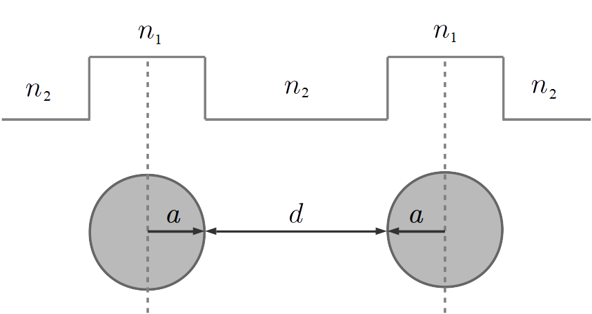
In the present work, we consider the particular case of double-guided structures consisting of two identical circular guides of radius , as illustrated in Fig. 1. Note that in this paper, we take the edge-to-edge separation to be (rather than 2 as in Ref. Vaughan et al. (2019a)). We choose values of the cladding refractive index and the refractive index in the guides such that, for the operating wavelength of , there are only two supported modes with even (for the lower order mode) and odd parity. We shall refer to these as the symmetric and anti-symmetric modes and denote them by respectively. The values we choose are and . By restricting the number of solutions in this way with such small differences in refractive index, the evanescent tails of the optical modes tend to extend into the cladding regions to a significant extent.
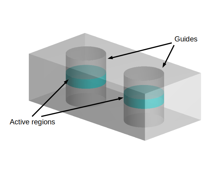
An slightly more intuitive sketch of the guiding arrangement, illustrating how such a guiding configuration relates to VCSELs is shown in Fig 2. This extends the view of Fig. 1 into the propagation direction of the light and indicates, schematically, the active regions. To keep the diagram simple, no attempt has been made to add in further detail such as the Bragg stack mirrors. Due to their equivalence at this level of abstraction, we shall use the terms ‘guide’ and ‘laser’ interchangeably throughout the text.
Limiting the number of modes to two, the notation required to denote the overlap factors may be specialised. Denoting the guide by the superscript , is the overlap of the symmetric modes, the overlap of the antisymmetric modes and is the cross product. Note that, due to the symmetry of the guides, we always have , due to the parity of the modes. Moreover, as the separation between them increases, we have and , where is the optical confinement factor of an isolated guide. The factor of 1/2 arises since the modes are normalised over all space, which includes 2 guides.
II.0.1 Normalised rate equations
The general form of the normal mode model and its reduction to the double-guided structure in dimensional and normalised form are derived in Ref Vaughan et al. (2019a). Here we shall just quote the normalised form used in our numerical calculations. The model has 11 independent variables: the spin-polarised carrier concentrations in each guide , where labels the guide and labels the spin up / down components respectively; the optical amplitudes in each guide , where labels the right-circularly / left-circularly polarised components respectively and three phase variables , and . The are the phase differences between and , which we shall refer to as the spatial phase. This is the phase of the coupled mode model of Ref Adams et al. (2017). The variable is the phase difference between and , which is the phase referred to in the literature of the SFM. We shall call this the polarisation phase. A fourth phase variable is related to the other three via .
Note that the are not the amplitudes of the modal solutions of the Helmholtz equation but rather ‘composite modes’ defined in terms of a superposition of the actual modal solutions (symmetric and anti-symmetric) to better exploit the symmetry of the waveguide. Specifically, these become the amplitudes of the local solutions in isolated guides as the separation between them is increased to infinity, retaining close similarity at nearer distances. Hence, they offer a more intuitive, physical representation of the optical field in each guide. The actual normal modes may be reconstructed from the composite modes and the phases using the procedure described in the appendix of Ref Vaughan et al. (2019a).
For convenience of formulation in the double-guided structure model, we introduce new terms defined in terms of the optical overlap factors by
| (2) |
and
| (3) |
Using these, we introduce further new variables defined via
| (4) |
| (5) |
and
| (6) |
in terms of which the optical rate equations are more concisely written.
The normalised carrier rate equations are
| (7) |
where are the polarised pumping rates in each guide, is the inverse of the carrier lifetime , is the spin relaxation rate and the polarised components of the optical intensity in each guide are given by
| (8) |
Note that in the normalised form of the SFM, the effective spin relaxation rate is often used.
The normalised optical rate equations are
| (9) |
| (10) |
| (11) |
and
| (12) |
The parameters of the optical model are the linewidth enhancement factor , the cavity loss rate , the dichroism rate , the birefringence rate and the coupling coefficient . Note that is given in terms of the modal frequencies by Marom et al. (1984); Vaughan et al. (2019a)
| (13) |
for the symmetric () and anti-symmetric () modes found from solution of the Helmholtz equation for the waveguiding structure.
It will be convenient to define the pump ellipticity in the th guide in terms of the right and left circular polarised pumping rates and by
| (14) |
Similarly, we may define the output optical ellipticity in the th guide via
| (15) |
We describe this as the ‘modal’ ellipticity since it is in terms of the composite mode amplitudes. Although this is defined for each guide, there is a spatial dependence beyond this. The actual ellipticity we would measure is given in terms of the spatially dependent components of the optical intensity via
| (16) |
where the are given in terms of the normal mode amplitudes by
| (17) |
Here, we have used the subscript to distinguish these as the amplitudes of the modal solutions of the waveguide (i.e. the solutions of the Helmholtz equation) rather than the ‘composite modes’ used elsewhere in this paper (as discussed above), which are denoted by the subscript . See Ref Vaughan et al. (2019a) for further details of this calculation.
III Results and discussion
III.1 Stability boundaries
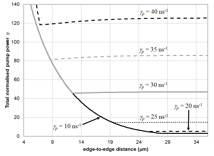
The dynamics of pairs of laterally-coupled lasers with circular guides of radius have been investigated by plotting stability boundaries in the plane, where is the total normalised pumping rate in either guide and is the edge-to-edge guide separation (Fig. 3). These plots are topologically equivalent to the scheme of v diagrams used in Refs Vaughan et al. (2019b) and Vaughan et al. (2019a), where and are the total pump power and threshold pump respectively. Here, because we may vary the pump ellipticity in each guide independently, is not well defined and so represents an inaccurate measure.
A similar stability map, in terms of v has been shown for the non-polarised case using the coupled mode model in Fig. 6 of Ref Adams et al. (2017). A remaining discrepancy between the results of the coupled mode model and the present work is due to the sensitivity of the dynamics to the overlap factors. It was shown in Ref Vaughan et al. (2019b) that, taking the asymptotic values of the overlap factors as the guide separation tended to infinity, the stability map for the non-polarised case reproduced that of the coupled-mode treatment in Ref Adams et al. (2017) exactly. This would then correspond to a birefringence rate of , which is almost indistinguishable from the case of plotted in Fig. 3.
For all the stability boundaries investigated here, we keep the total normalised pumping rate the same in each guide and so may be conveniently plotted in the plane. In the regions of instability, we typically see oscillatory behaviour of the type reported in Section III.2.3.
| Parameter | Value | Unit | Description |
|---|---|---|---|
| -2 | Linewidth enhancement | ||
| 70 | Cavity loss rate | ||
| 1 | Carrier loss rate | ||
| 0.1 | Dichroism rate | ||
| 100 | Effective spin relaxation rate | ||
| Transparency density | |||
| Differential gain | |||
| 3.4 | Group refractive index |
Note, we tabulate the effective spin relaxation rate to aid direct comparison with the SFM model. These are the same parameters as used in Ref. Vaughan et al. (2019a) except that in this paper we vary the birefringence rate .
In Ref. Vaughan et al. (2019a) stability boundaries were plotted for devices with a small birefringence rate of , which gives very little coupling between the right and left circularly polarised components of the optical field. These gave rise to Hopf bifurcations qualitatively similar to the curve for shown in Fig. 3, up to around (in these calculations, all other parameters have been kept the same as in Ref. Vaughan et al. (2019a) for the purposes of comparison). In this earlier work, the stable, steady state solutions found above the curve were termed ‘out-of-phase’ solutions, in keeping with the terminology of the coupled mode model Adams et al. (2017). In terms of the normal mode model, such out-of-phase solutions correspond to the anti-symmetric normal modes (at large separation, these tend to the solutions of isolated guides with a phase difference of between them, meaning the amplitudes are inverted). This phase relation is associated with the variables, i.e. at large separation . Earlier, we designated this the spatial phase to distinguish it from the polarisation phase associated with the variables.
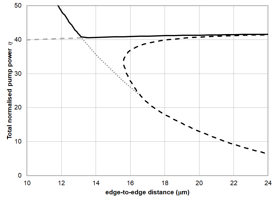
The graphs in Fig. 3 are calculated for pump ellipticities of (i.e. for linearly polarised pumps). In Ref Vaughan et al. (2019a) it was shown that, in general, the stability boundaries tended to move towards the origin as the pump ellipticity moves away from zero. In this work, we investigate the effect of increasing the birefringence rate , which has the effect of coupling power between the opposite circular components of the optical polarisation. Here, we see the emergence of a new stability boundary moving roughly horizontally across the plane and increasing in as increases. These boundaries are plotted for the polarisation in-phase solutions, for which is close to zero. These are characterised by the fact that the output optical ellipticity takes the same sign as the pump ellipticity. On the other hand, the ellipticity of the polarisation out-of-phase solutions, for which is close to , has the opposite sign to the pump ellipticity.
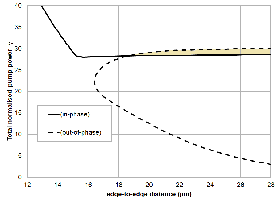
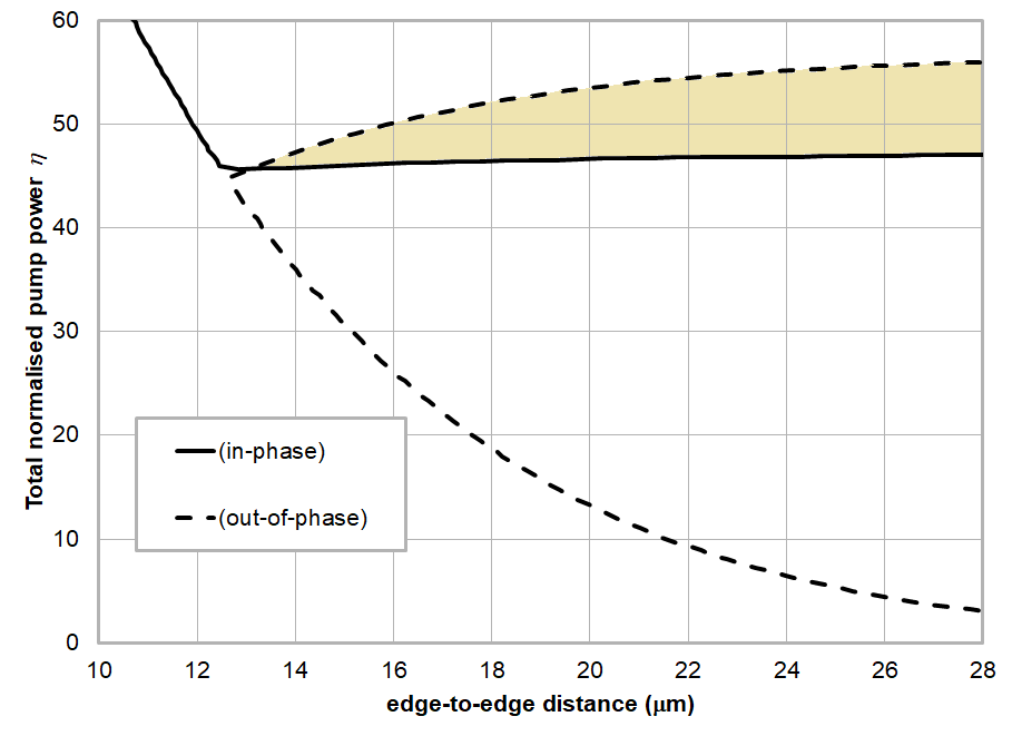
Stability boundaries for both in-phase and out-of-phase solutions for for and values of from 0 to 0.8 are shown in Figs 4 to 8 (from here on, we shall be referring to the polarisation phase whenever we speak of in-phase or out-of-phase solutions without specific qualification). These show the out-of-phase stability boundaries as dashed lines with the stable solutions to the right of the curved borders and beneath the horizontal borders. Investigating the sharp kinks in the borders, we find that this is due to the continuation of Hopf bifurcations into the unstable regions. An example is shown in Fig. 5 in the case of
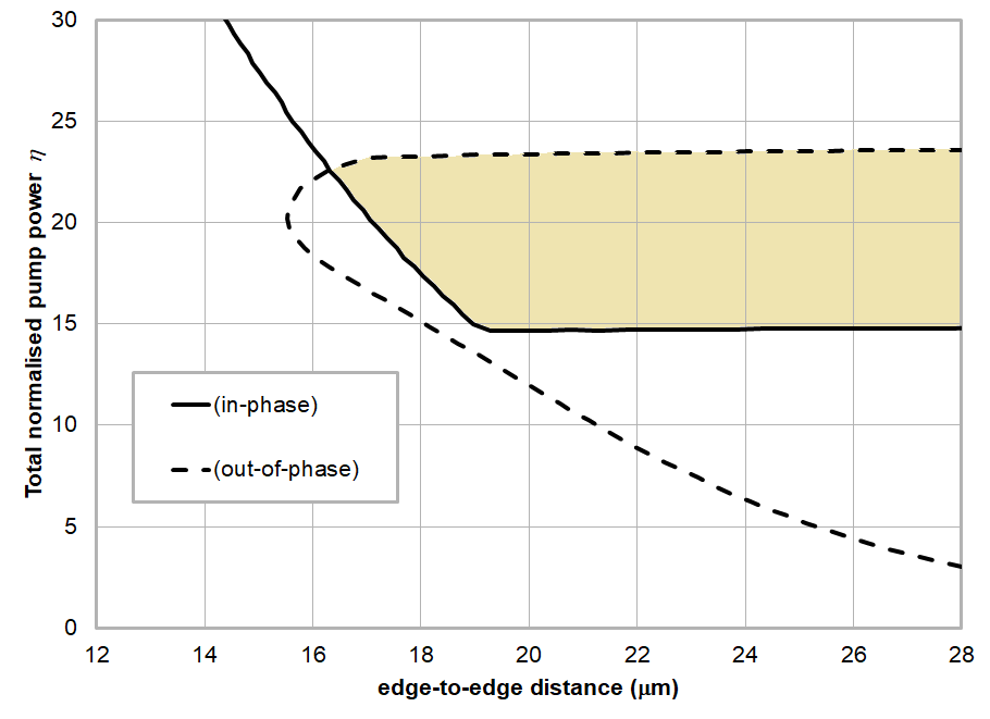
A clear feature of these stability boundaries is that, in most cases, the out-of-phase boundary crosses that of the in-phase boundary creating regions of bistability where both types of solution are stable. These are shown as the shaded areas and suggest the possibility of optical switching between these stable states. This is investigated in the next sub-section, where we find that optical switching via pump power and / or ellipticity is indeed achievable.
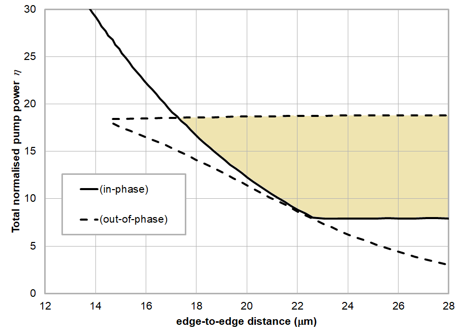
In the case of , we note that, unlike the other cases shown, there is no region of bistability in domain plotted. At this point, however, we can offer no definitive explanation for this behaviour.
III.2 Bistability
III.2.1 Switching both lasers together on pump power
We have examined the dynamics within the bistable regions via time series solutions of the rate equations using the Runge Kutta method (technical details are given in Ref. Vaughan et al. (2019a)). Each time series is run for a simulation time of 400 ns for a given pump power and ellipticity in each guide. The output solutions at the end of each solution are then used as the intial conditions for the next simulation with different pumping parameters. In this way, we can see how the system behaves as we vary these parameters smoothly or in sharp jumps.
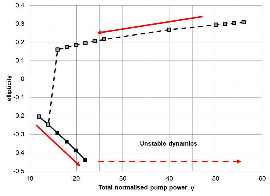
For an initial set of simulations, we keep the birefringence at , take the edge-to-edge separation to be and the pump ellipticity in either guide to be . The stability boundaries in this case are shown in Fig. 7. We start the simulation with equal pump power . From Fig. 7 we can see that this is in a region of instability for the in-phase solution but just on the edge of the stable region for the out-of-phase solution. We then start increasing the pump power in both guides and track the modal output optical ellipticity , given by (15). This is shown in Fig. 9, where at we have and track down to , following the direction of the red solid arrow. After this point, we enter into a region of unstable dynamics where the system fails to settle down to the in-phase steady state solution until the power reaches . This is indicated by the dashed red arrow. At this point, we track back, ramping down the power. This time, the system remains in the in-phase steady state solution all the way through the bistable region until it cross the Hopf bifurcation delimiting the in-phase dynamics and the system drops to the out-of-phase solution.
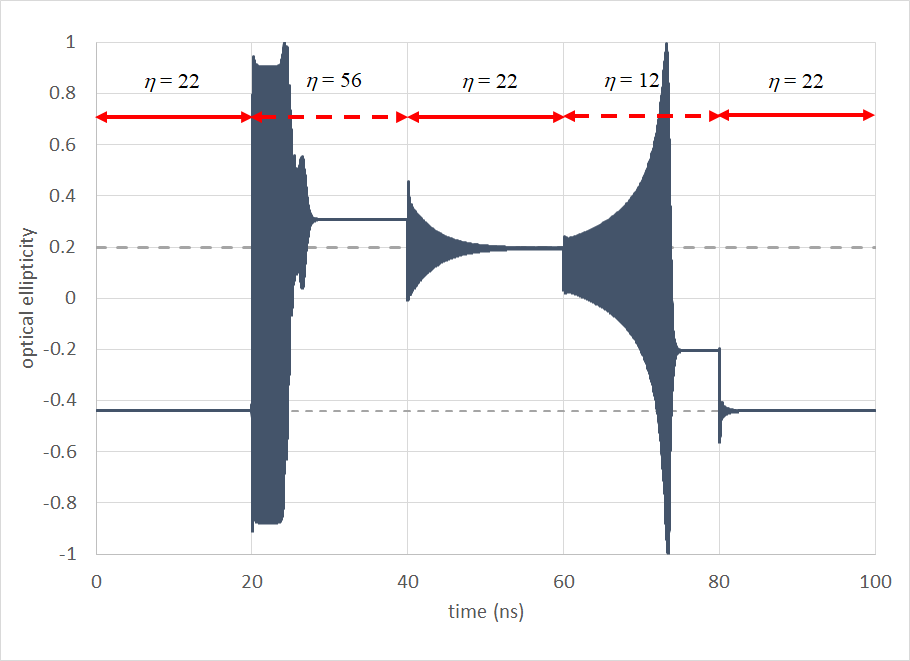
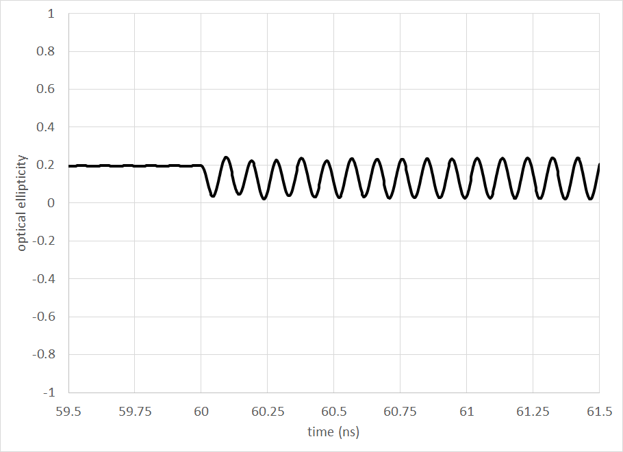
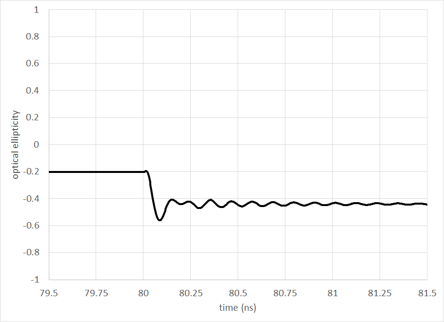
It is natural to ask whether we may obtain switching behaviour by applying step changes to the pump. To investigate this, we start the system off in an out-of-phase steady state solution with in both lasers. This gives an output ellipticity of . We then step up the power to for a period of 20 ns. This settles down to a steady-state in-phase solution with after about 9 ns as shown in Fig 10. After this, the power is dropped back down to . However, the system now settles down in an in-phase steady-state with . Again, it takes aroung 9 to 10 ns for the system to settle to the steady-state solution. Following this, the power is further dropped to and the system switches to an out-of-phase solution with . Finally, stepping the power back up to , we arrive back at the out-of-phase solution with . Hence, we can use the pump power for the purposes of optical switching, with an overal switching time of around 20 ns in this case (giving a possible switching rate of around 8 MHz).
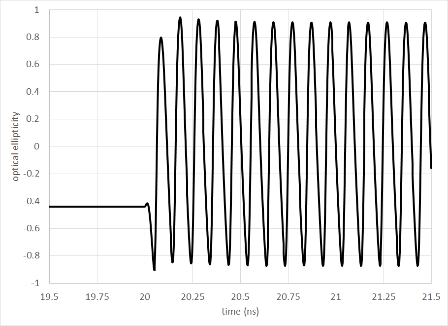
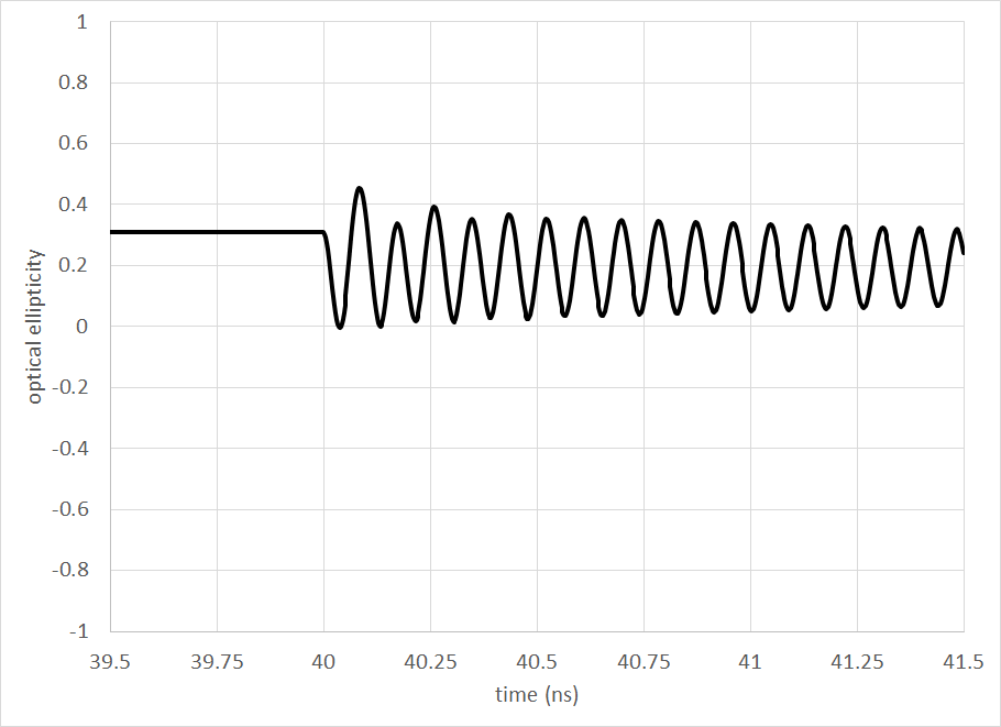
The switching dynamics are explored in more detail in Figs. 11 to 14 on the sub-nanosecond time-scale. Fig. 11 shows the dynamics as the system is switched from the out-of-phase solution at to the in-phase at . We see on this scale that the behaviour is oscillatory, varying between around to with an angular frequency of approximately 64 radns-1 (10 GHz). Figs. 12 to 13 show the steps from to and to respectively on the same scale, with similar angular frequencies of 72 radns-1 (11 GHz) and 66 radns-1 (11 GHz). In the final step from to shown in Fig. 14, the system settles down much faster. The angular frequency of the oscillations in this case is around 58 radns-1 (9.2 GHz).
It may seem natural to seek an explanation for this oscillatory behaviour in terms of relaxation oscillations. We can explore this possibility using the expression for the angular frequency of damped oscillations given in Ref. Adams et al. (2017) derived from a stability analysis of the coupled mode model
| (18) |
where is the damping rate given by
| (19) |
However, for values of and , using (18) we obtain values of and 39 ns-1 respectively, showing a strong dependence on the pump power .
Instead, we note that in the analysis of spin-polarised VCSELS Gahl et al. (1999); Li et al. (2017); Lindemann et al. (2019), it has been found that the frequency of birefringence-induced oscillations was mainly determined by the birefringence rate , given approximately by for large (in GHz if is given in ns-1). In our case, we have 30 ns-1, giving 9.5 GHz, which is very close to the observed frequency in the numerical simulations.
III.2.2 Switching one laser via the other
Having verified that is possible to switch the ellipticity of the lasers in the bistable region by varying the pump powers in each simultaneously, we next investigate the possibility of switching one laser purely by varying the pump on the other, hence via the coupling between them. The following is a proof of concept and is not supposed to represent the optimal conditions for such functionality.
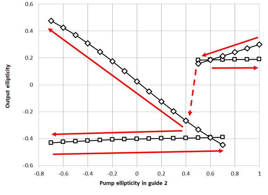
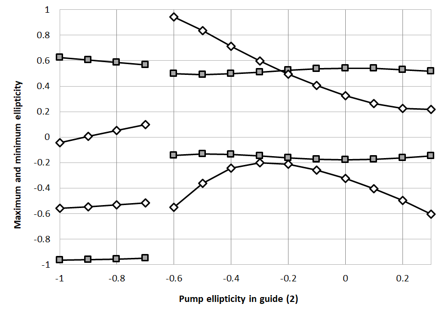
The edge-to-edge separation is taken to be a little shorter at and for the initial investigation, the total pump power in either guide is held fixed at . The birefringence is as before. Initially, the pump ellipticity is set at in both guides and the simulation is started with both lasers in the steady-state in-phase solution. is kept fixed throughout and is then varied, initially being increased to and then reduced again to (see Fig. 15). Throughout this range, both solutions remain in a stable in-phase solution. However, below , both lasers drop to an out-of-phase steady-state solution, which then varies smoothly as is reduced to -0.7. During this variation, the laser in guide (1) remains in an out-of-phase solution, whilst the ellipticity in guide (2) varies linearly from an out-of-phase solution to an in-phase solution. Beyond , neither laser settles to a steady-state.
As is increased to , the ellipticity tracks back over its previous values and then continues to vary smoothly past the point where the in-phase solution dropped to the out-of-phase solution. These behaviours are shown in Fig. 15 where the square points show the ellipticity in guide (1), the diamond points show the ellipticity in guide (2) and the red arrows indicate the directions in which is varied.
In fact, it is found that once the system is on the lower line of Fig. 15 with guide (1) in an out-of-phase steady-state solution, it cannot be switched back to an in-phase state by varying . This can only be achieved by varying the pump power. However, it can be achieved by only varying the pump power in laser (2), so the goal of switching one laser purely by coupling with the other is achievable.
Specifically, we can use the following sequence: Starting with and in the in-phase solution, we have . Stepping to 0.4, drops to -0.40. Putting back to 0.6, changes very little, with . If we now step up to 60, the ellipticity in guide (1) then changes to . Dropping the power in guide (2) back down to 20, we end up again in the original in-phase solution with . For this particular set of parameters, the switching time is quite slow, taking around to settle down to the steady-state solutions.
III.2.3 Oscillations in the ellipticity
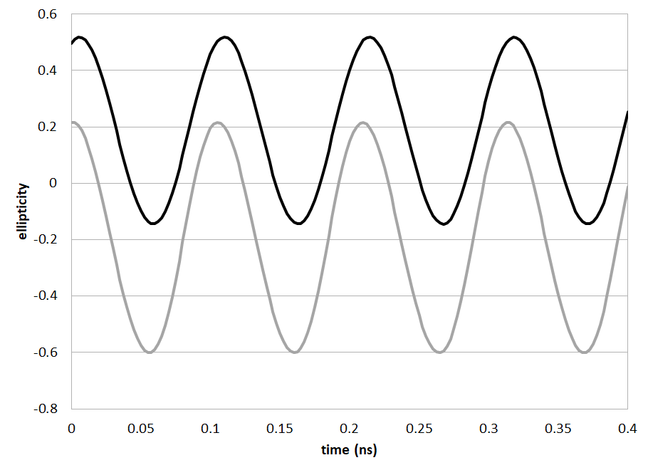
This switching behaviour on the basis of variation of does not occur under all conditions within a bistable region. At , the variation in the output ellipticities is similar to that shown in Fig. 15 except that there is drop from the steady-state in-phase solutions to the out-of-phase steady-state solutions as is reduced. Instead, the system becomes unstable with the ellipticity oscillating as shown in Fig. 16 for .
IV Conclusions
A recently-developed theory of evanescently-coupled pairs of spin-VCSELs has been applied to study the dynamics of structures with two identical circular cylindrical waveguides and realistic material parameters. Stability boundaries in the plane of total normalised pump power versus edge-to-edge spacing of the lasers have been presented for the cases of (1) zero pump polarization ellipticity with varying birefringence rate, and (2) fixed birefringence and varying pump ellipticity, with equal pump power in each laser for all cases. Boundaries for in-phase and out-of-phase solutions are found in terms of the spatial phase of the normal modes of the system. It is shown that intersection of these boundaries can give rise to sharp ‘kinks’ in the overall stability boundaries for some pump ellipticities, whilst for others crossing of the in-phase and out-of-phase solutions can yield regions of bistability. The dynamics of the coupled spin-VCSELs in the bistable regions have been examined by time series solutions of the rate equations. It is shown that it is possible to switch the output ellipticity of the lasers by varying the pump powers in each simultaneously. It is also possible to switch the output elllipticity of one laser by varying the pump ellipticity or pump power of the other, under certain operating conditions. For other conditions, however, values of the pump ellipticity of one laser can be found that produce oscillatory behaviour of the output ellipticities of both lasers. Thus, it has been demonstrated that evanescently-coupled pairs of spin-lasers can yield a rich variety of different dynamics. Further work is needed to explore the effects of varying material, device and operating parameters and hence to investigated potential applications of these dynamics.
Acknowledgement
This research was funded by the Engineering and Physical Sciences Research Council (EPSRC) under grant No. EP/M024237/1.
References
- Gao et al. (2017) Z. Gao, S. T. Fryslie, B. J. Thompson, P. S. Carney, and K. D. Choquette, Optica 4, 323 (2017).
- Gao et al. (2018) Z. Gao, M. T. Johnson, and K. D. Choquette, Journal of Applied Physics 123, 173102 (2018).
- Gao et al. (2019) Z. Gao, B. J. Thompson, H. Dave, S. T. Fryslie, and K. D. Choquette, Applied Physics Letters 114, 061103 (2019).
- Dave et al. (2019) H. Dave, Z. Gao, S. T. M. Fryslie, B. J. Thompson, and K. D. Choquette, IEEE Journal of Selected Topics in Quantum Electronics (2019).
- Fryslie et al. (2017) S. T. Fryslie, Z. Gao, H. Dave, B. J. Thompson, K. Lakomy, S. Lin, P. J. Decker, D. K. McElfresh, J. E. Schutt-Ainé, and K. D. Choquette, IEEE J. Sel. Top. Quantum Electron. 23, 1 (2017).
- Xiao et al. (2017) Z.-X. Xiao, Y.-Z. Huang, Y.-D. Yang, M. Tang, and J.-L. Xiao, Optics letters 42, 3173 (2017).
- Han and Shore (2018) H. Han and K. A. Shore, Optics express 26, 10013 (2018).
- Kominis et al. (2019) Y. Kominis, K. D. Choquette, A. Bountis, and V. Kovanis, IEEE Photonics Journal 11, 1 (2019).
- Pan et al. (2018a) G. Pan, Y. Xie, C. Xu, Y. Dong, J. Deng, H. Chen, and J. Sun, Photonics Research 6, 1048 (2018a).
- Pan et al. (2018b) G. Pan, Y. Xie, C. Xu, M. Xun, Y. Dong, J. Deng, and J. Sun, IEEE Electron Device Letters 39, 390 (2018b).
- Pan et al. (2019) G. Pan, C. Xu, Y. Xie, Y. Dong, Q. Wang, J. Deng, J. Sun, and H. Chen, Optics express 27, 13910 (2019).
- San Miguel et al. (1995) M. San Miguel, Q. Feng, and J. V. Moloney, Phys. Rev. A 52, 1728 (1995).
- Vicente et al. (2006) R. Vicente, J. Mulet, C. R. Mirasso, and M. Sciamanna, Optics letters 31, 996 (2006).
- Jiang et al. (2017) N. Jiang, C. Xue, D. Liu, Y. Lv, and K. Qiu, Optics letters 42, 1055 (2017).
- Guo et al. (2019) X. X. Guo, S. Y. Xiang, Y. H. Zhang, L. Lin, A. J. Wen, and Y. Hao, Optics Express 27, 23293 (2019).
- Lindemann et al. (2019) M. Lindemann, G. Xu, T. Pusch, R. Michalzik, M. R. Hofmann, I. Žutić, and N. C. Gerhardt, Nature 568, 212 (2019).
- Vaughan et al. (2019a) M. Vaughan, H. Susanto, I. Henning, and M. Adams, arXiv:1912.06882 [physics.optics] (in submission) (2019a).
- Vaughan et al. (2019b) M. Vaughan, H. Susanto, N. Li, I. Henning, and M. Adams, Photonics 6, 74 (2019b).
- Adams et al. (2017) M. Adams, N. Li, B. Cemlyn, H. Susanto, and I. Henning, Phys. Rev. A 95, 053869 (2017).
- Marom et al. (1984) E. Marom, O. Ramer, and S. Ruschin, IEEE J. Quantum Electron. 20, 1311 (1984).
- Gahl et al. (1999) A. Gahl, S. Balle, and M. S. Miguel, IEEE J. Quantum Electron. 35, 342 (1999).
- Li et al. (2017) N. Li, H. Susanto, B. Cemlyn, I. Henning, and M. Adams, Phys. Rev. A 96, 013840 (2017).