Commensurate and incommensurate double moire interference in graphene encapsulated by hexagonal boron nitride
Abstract
Interference of double moire patterns of graphene (G) encapsulated by hexagonal boron nitride (BN) can alter the electronic structure features near the primary/secondary Dirac points and the electron-hole symmetry introduced by a single G/BN moire pattern depending on the relative stacking arrangements of the top/bottom BN layers. We show that strong interference effects are found in nearly aligned BN/G/BN and BN/G/NB and obtain the evolution of the associated density of states as a function of moire superlattice twist angles. For equal moire periods and commensurate patterns with modulo angle differences the patterns can add up constructively leading to large pseudogaps of about eV on the hole side or cancel out destructively depending on their relative sliding, e.g. partially recovering electron-hole symmetry. The electronic structure of moire quasicrystals for differences reveal double moire features in the density of states with almost isolated van Hove singularities where we can expect strong correlations.
1 Introduction
Research on vertical heterostructures of atomically thin two-dimensional van der Waals (vdW) materials has been a booming field [1, 2, 3] thanks to the new opportunities for tailoring artificial materials with novel electronic properties, for which magic angle twisted bilayer graphene [4] or trilayer graphene on hBN [5, 6] have emerged as prototypical systems where signatures of Mott insulating phases and superconductivity have been observed. In particular, the hexagonal boron nitride (BN) [7] is an excellent substrate material that preserves the properties of pristine graphene (G) and introduces moire super-lattice features at experimentally accessible magnetic fields and gate voltages when they are nearly aligned [8, 9, 10, 11, 12, 13, 14]. Experiments in G/BN systems can make use of an additional capping BN dielectric film that further screens the system from extrinsic disorder and improves the device mobilities [15, 16]. These are often deposited at wide twist angles to avoid potential interference with the moire pattern of the BN substrate. With increasing precision in the rotation angle control of 2D materials [17, 18] it is desirable to understand what would be the combined effects where both encapsulated layers are nearly aligned with the graphene layer. Recent experiments of graphene encapsulated by nearly aligned boron nitride sheets indicate enhancement of primary Dirac point band gaps and additional density of state peaks near the secondary Dirac point [19, 20] that can be expected from the momentum conservation conditions for the electrons traveling in a double moire system [21]. The superposition of moire patterns has also been considered as a tool to characterize multilayer systems via atomic moiré interferometry [22] and traces of this interference on the electronic structure have also been observed at finite magnetic fields [20]. Other terminology used include super-moires (SM) [21, 23] in graphene encapsulated by boron nitride, and equivalently moire of moires [24] in twisted trilayer graphene.
In this paper we investigate the effects of superposing two moire patterns in the parameter space of twist angles and sliding vector magnitudes of the BN sheets at each interface that encapsulate the reference graphene sheet. We pay particular attention to the double moire structures that have not been addressed in earlier literature, namely the different commensurate and quasi-crystal limits where the double moire features show up in a special manner. The resulting moire patterns will have a relative rotation of and for equal moire periods we can achieve commensurate patterns for angle differences while moire quasicrystals are expected for differences. The interference between the secondary Dirac point features for nearly aligned moire patterns can add up constructively or destructively, depending on both the relative sliding between bottom and top hBN layers as well as the respective orientation of the top layer with respect to the bottom layer ( or ) at energies where families of super-moire features converge. We also observe that in the incommensurate regime, the relative strength of super-moire features are only weakly dependent on the orientation and the periods of the constituent moire patterns, while strongest features happen close to charge neutrality and near the secondary Dirac point on the hole side where significant suppressions in the density of states take place.
2 Electronic structure of aligned BN/G/BN and BN/G/NB configurations
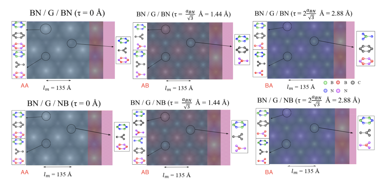
Let us consider graphene sandwiched between two BN layers where the graphene layer is the fixed reference frame and the twist angles and refer to the bottom and top BN layers respectively. The simplest commensurate double moire structures can be formed when where the two BN layers have the same orientations which we label as BN/G/BN, or and configurations where the top BN layer has a different alignment which we label as BN/G/NB, see Fig. 1. We define the sliding vector along the -axis to represent the difference between the top and bottom BN layers with respect to the central graphene reference system.
The effective Hamiltonian of graphene subject to the moire potentials stemming from both BN layers can be written as
| (1) |
where the Hamiltonian of graphene is modeled with a finite gap of that appears due to alignment with BN
| (2) |
and we use the Pauli matrices and that operate on the sublattice and valley pseudospins respectively. Since the primary focus of our work is for the interference effects in double moire patterns for the analysis presented in this work we set the primary Dirac point gap to zero but they should be accounted for explicitly in a theory that intends to resolve the band gaps near charge neutrality. The moire patterns for the top and bottom interfaces are added to account for the double moire
| (3) |
where the indices can take values depending on the G/BN or G/NB orientations irrespective to whether the BN layer is above or below the graphene layer. The moire pseudospin components are
| (4) |
| (5) |
for the diagonal terms with which is complex conjugated when the sign of is reversed. We use the reciprocal lattice vectors of the reference frame lattice and the local stacking function
| (6) |
where is the scaling ratio with respect to the reference lattice and is the rotation operator acting on an arbitrary point in real space at lattice . The off-diagonal component is given by
| (7) |
where we use the vector notation to distinguish the real and imaginary parts. The moire pattern rotation angle for small satisfies [25]. The tight-binding (TB) model in real space is obtained by mapping the continuum moire patterns into real-space as introduced in Ref. [26]. The sublattice diagonal terms of the TB Hamiltonian can be mapped in a straightforward manner as site potential energies from Eqs. (4) and (5). For the off-diagonal term we note that following the definition of the Pauli matrices, and using the sublattice definitions of Refs. [25, 26] we have
| (8) |
where the correction terms to the pristine graphene hopping of eV capture the unequal hopping amplitude of the electrons from A to B sites due to the moire pattern of strains and they are given by
| (9) |
where and are evaluated at the Brillouin-zone corner of graphene . The parameters defining our model correspond to the non-relaxed G/BN system and they are given by [25]
| (10) |
that are equivalent to those of Ref. [13] but have been updated to use positive magnitudes for the coefficients and the redefined phase following the conventions in Ref. [25]. The density of states are calculated using the Lanczos recursion method [27, 28] using 10000 recursion steps on about 80 million atom systems for the data in Figs. 2, 5 and 6 and 4000 recursion steps on about 20 million atoms for the DOS maps in Figs. 4. The energy broadening in the Lanczos method is increased from its arbitrarily small value in the previous maps to about 1.5 meV for the DOS curves in Figs. 2 and 5 to damp numerical oscillations.
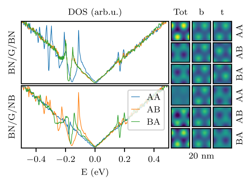
For the aligned and commensurate moire geometries, referred to as hereon, the relative sliding between the top and bottom BN layers can give rise to very different electronic structures, see Fig. 2 for the plot of the different density of states. We can for instance recover a certain electron-hole symmetry due to destructive interference effects for BN/G/NB in AA-stacked arrangement, as rationalized by the vanishing features in the corresponding moire contribution maps, or find strong increases in the DOS dip due to constructive interference effects as compared to BN/G for BN/G/BN in AA arrangement and in agreement with recent experimental observations on such systems [19, 23].
3 Commensurate and quasi-crystalline double moire patterns
In our simulations, we use the effective model for the moire pattern potentials consistent with the conventions for the reference frame and relative lattice constants outlined in Ref. [13] where the moire pattern angle for a layer rotated by from a reference frame is given by
| (11) |
using the scaling parameter accounts for the lattice constant mismatch with respect to a reference frame lattice constant , where the minor differences with respect to Ref. [8] are related with the conventions in the choice of the reference frames. When one BN layer is used as a reference frame lattice an approximate fractional value can to account for the reduction of graphene’s lattice constant with respect to that of BN while facilitates constructing commensurate moire supercells. The period of the resulting moire pattern is given by .
In this section we consider supermoires (SM) arising from double moires for which we can use the same formula as in the ordinary moire patterns stemming from two rotated lattices in Eq. (11) by substituting and to obtain the supermoire lengths and twist angles . The electrons in a double moire that gives rise to a SM obey momentum conservation rules that are similar to that of electrons in incommensurable double lattices within a moire superlattice. The reciprocal lattice of the SM is given by
| (12) |
where and are the reciprocal lattice vectors associated to each one of the two moire patterns [29]. We note that multiple SM reciprocal lattices are possible but we will restrict our attention to values of the moire lattices. In Fig. 3 we show a schematic representation of a SM formed by two equal period moire potentials twisted in opposite angles.
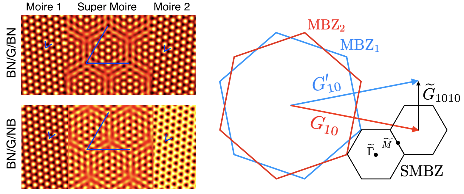
The SM features are expected at energies in the SMBZ boundaries at momenta . Assuming a linear Dirac dispersion these energies are
| (13) |
where we use the notation for each set of values which reduces to the form proposed in Refs. [23, 29] at energies for a SM period given by .
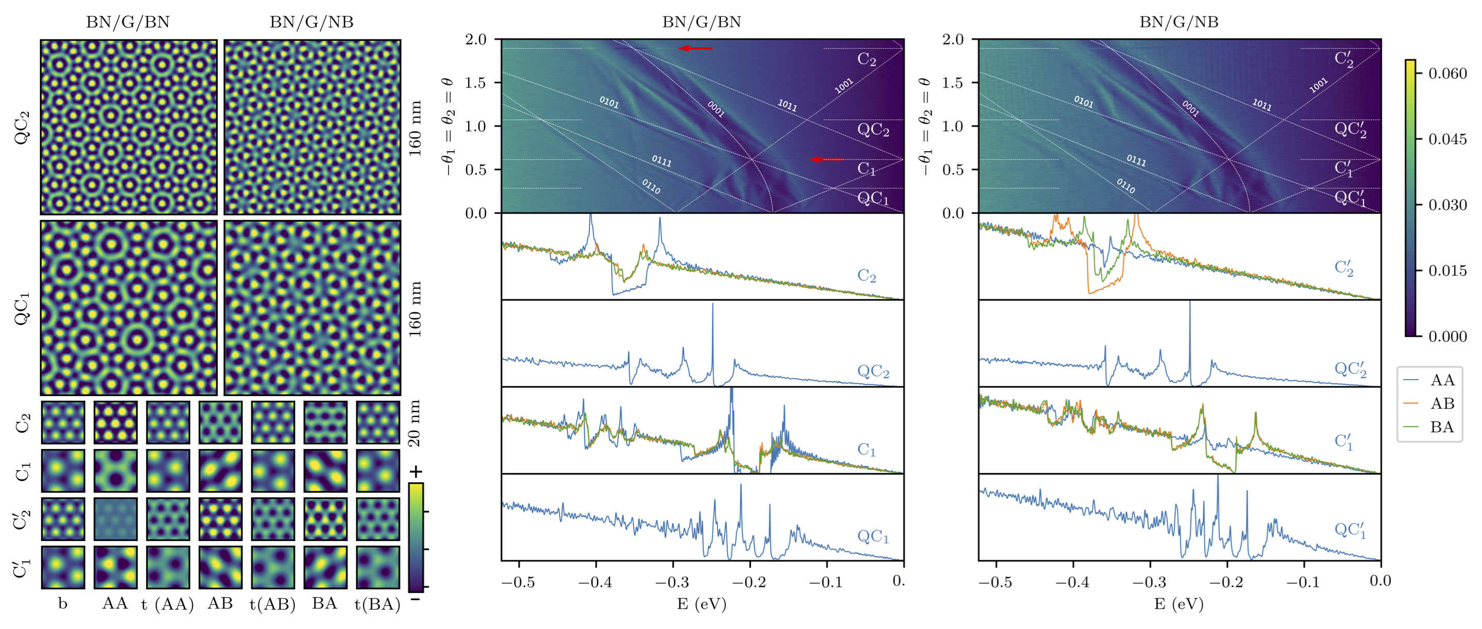
We begin by considering equal period moire patterns for the bottom and top layers for variable and we illustrate in Fig. 4 the colormap for hole density of states (DOS) for small twist angles up to . On top of it we also plot as a guide to the eye the dashed white lines the energies at the point of the SMBZ assuming a Dirac cone energy dispersion given in Eq. (13) for SM reciprocal lattice vectors corresponding to , , , = 0, 1. These energies show good overall agreement with features in the DOS obtained from explicit electronic structure calculations while deviations thereof can be attributed to the moire superlattice band features in G/BN that distort the Dirac Hamiltonian. These select angles for the C and QC solutions obtained from Eq. (11) are , , , and . We use the prime symbols to denote a rotation by of the top moire system that switches the respective positions of top layer B(oron) and N(itrogen) atoms. From Fig. 4 we observe that for those select twist angles the multiple SM features merge to potentially enhance the electronic structure features. As an illustration of the double moire patterns for those select angles we plot the real-space map of the terms defined in Eqs. (4) and (5) where we can observe commensurate triangular double moire patterns with for C1, C2 cases, and dodecahedral quasicrystal patterns with double moire patterns for QC1, QC2 cases.
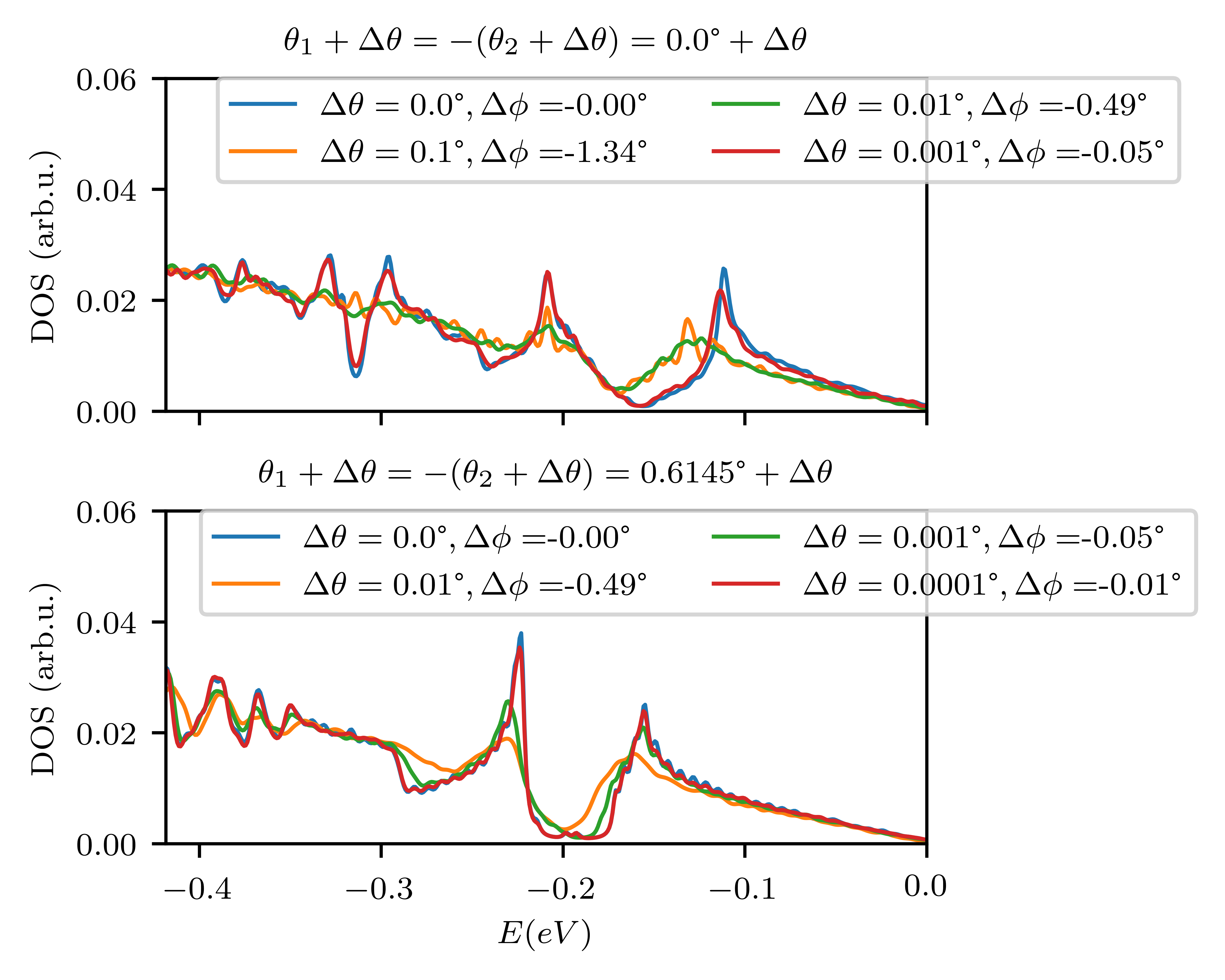
The solutions for commensurate double moires C, C show up as singular discontinuous points in the phase space of twist angles that we marked with red arrows in the middle panel of Fig. 4 and these are points where the SM features from different moire reciprocal lattice vectors cross each other at those specific energies, signaling potentially stronger interference of the moire features. The solutions are found to depend strongly on the specific sliding of the top BN layer moire pattern relative to bottom where we allowed the top layer moire to slide along the -axis by 0, and to for AA, AB and BA high symmetry stacking configurations. While the commensurate features in Fig. 2 and 4 show striking double moire interference the discontinuities indicated by the red arrows in Fig. 4 also suggest they are quite sensitive to small departures from perfect alignment. We illustrate this point in Fig. 5 where we show the DOS for the simple commensurate double moire consisting of two aligned BN layers with (C0) and the C1 case. We see that in both panels, the strong features stemming from constructive interference, including secondary gaps at around eV in the top panel and eV in the bottom panel, have already vanished for twist angles of the order of because these twists imply a much larger mismatch of the order of between the orientations of the respective moire patterns. Yet, experimental observations of practically aligned commensurate double moire systems [19] suggest that the moire systems might energetically lock into maximum alignment thus providing support that commensurate double moire patterns are within experimental reach. Strongest SM features are expected for the AA stacked C1 case where we find a remarkable suppression in the density of states near the secondary Dirac point showing a rather large gap-like structure 0.5 eV. This value is an order of magnitude larger than observed secondary Dirac point gaps of 12 meV in a single G/BN interface resolved in recent experiments [30] and would show unequivocally in experiments. Although these features are partially suppressed when the double moire pattern is modified to the AB or BA stacking, there is still a remarkable suppression in the electronic density of states around the secondary Dirac point energies far greater than that produced by a single moire pattern. We notice a progressive suppression of the moire features in the C configuration where a similar gap-like feature survives for AB and BA stacking but largely disappears for AA stacking, due to the mutual cancellation of the moire patterns effects between the top and bottom layer moires. In the C cases we see significant secondary Dirac point features for greater twist angles at energies of eV which should be accessible through ionic liquid gating techniques but are outside reach using ordinary gating techniques based on low permittivity dielectric barrier materials.
The QC1 and QC2 moire quasicrystals are formed for specific twist angles where . The associated DOS maps show clear traces of SM features stemming from moire interference effects with a large number of spikes that are partially smoothened by the broadening intrinsic to the calculations. Multiple split DOS spikes are result from the interference effects and the features are strongest in the vicinity of the energies where the G/BN secondary Dirac point dips exist on the hole side. The major van Hove singularity peaks near eV and near eV for QC1 are surrounded by suppressions in the DOS leading to a practically isolated DOS peaks making in principle the QC double moire systems a promising platform for finding Coulomb interaction driven physics. The QC2 shows a well defined prominent van Hove singularity peak that is located farther away from charge neutrality than in QC1 but yet at carrier densities that should be accessible in experiments. Differences between BN/G/BN and BN/G/NB encapsulations are rather weak in the DOS maps although their real space LDOS maps may show contrasting behaviors. Further studies on the properties of these moire quasicrystals will be presented elsewhere.
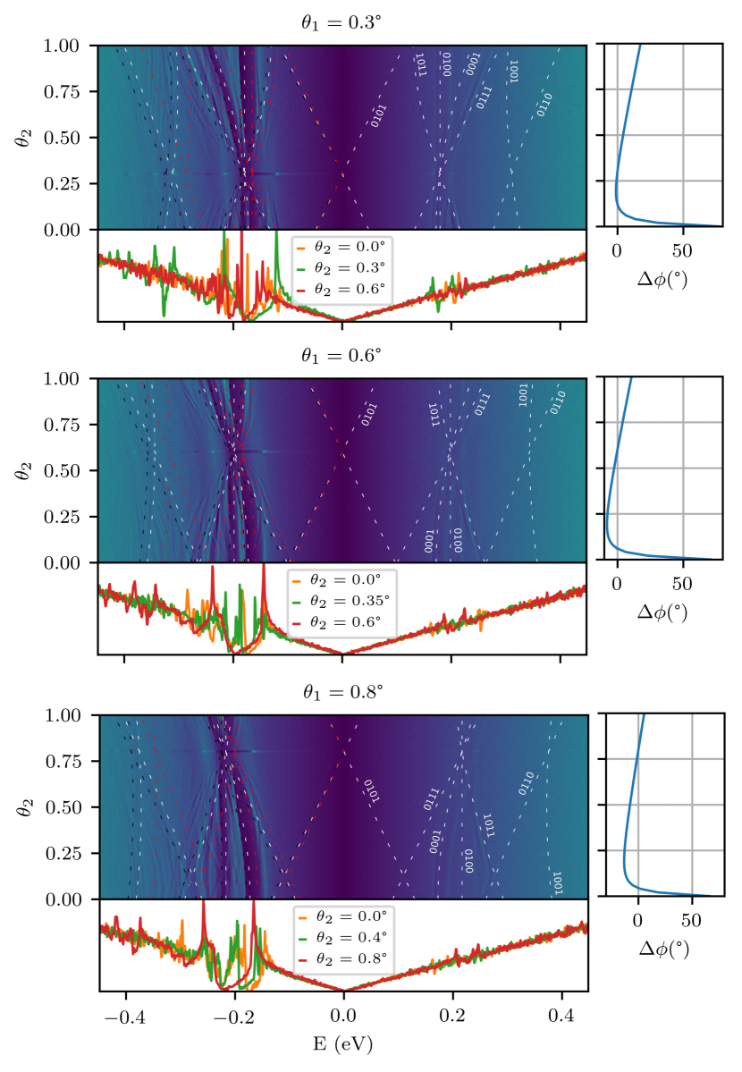
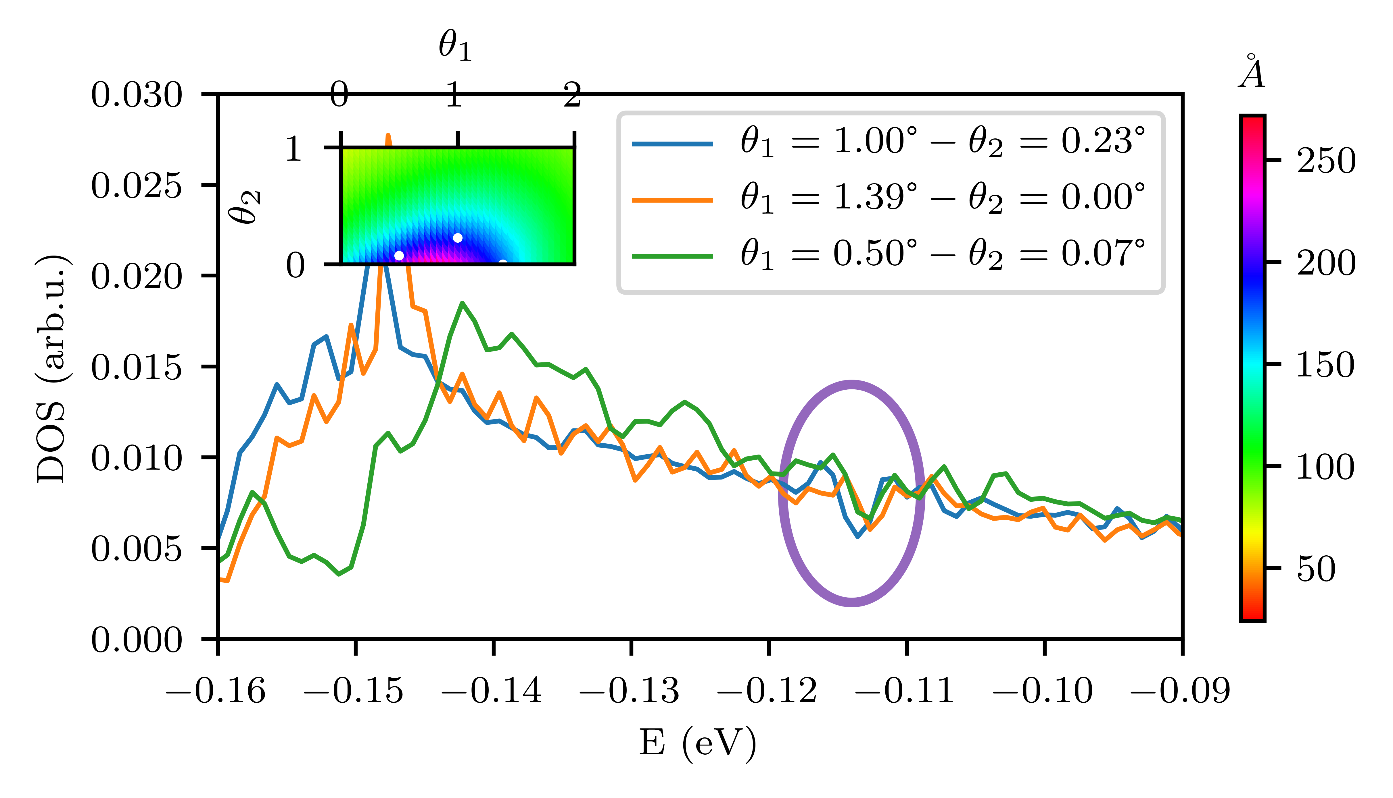
So far we have shown that modifications in the electronic structure appear at energies that are related with the SM periods, yet these are in turn sensitive to the period and orientation of each moire pattern. In order to illustrate the sensitivity of SM effects and therefore of moire periods and orientations we show in Fig. 6 and Fig. 7 additional DOS for systems showing unequal twist angles between bottom and top BN layers. For Fig. 6 we have obtained the DOS maps for different sets of fixed bottom BN layer twist angles of , , , allowing for a variable top BN layer twist angle . These calculations confirm that the traces of the SM features in the DOS colormap closely follow the single major parameter , namely the SM period associated to given moire reciprocal lattice vectors and are insensitive to . Specifically for fixed , when changes from to , varies continuously from about down to about back up to about . Despite this wide changes in the moire twist angles we see a relative stability in the strength of the DOS features appearing on the hole side near the secondary Dirac point energies. As the multiple supermoire features evolve into one single point as discussed earlier for commensurate systems. We further show in Fig. 6 relevant departures of the SM features on the DOS predicted from a Dirac dispersion through Eq. (13) and the actual calculations where the features are pushed to slightly lower energies. This behavior can be fitted using a reduced Fermi velocity in the regime where the supermoire features are modifying the DOS over a larger part of the spectrum, e.g., in the middle panel, to eV for and . We illustrate through black, white and red dashed lines the energies of the SM features from Dirac models using , and , respectively where is the Fermi velocity of graphene used in our simulations. The effective Fermi velocities of the Dirac model that fit best the SM features based on Eq. (13) depend continuously on the and twist angles of the BN layers and the range of energies explored, while it is expected that these SM features will be predicted more accurately by feeding the reference electronic structure bands from the G/BN moire bands corresponding of each BN interface rather than the bare Dirac cone dispersion. We further confirm the relevance of the SM length as the main parameter defining the energy scale of the SM features by comparing the DOS maps for three different cases that predict a SM feature at the same energy circled in purple in Fig. 7. These three different cases have different moire lengths and different values of , with the green line corresponding to a nearly perfectly aligned system, while the two others correspond to moire patterns that are not aligned). Yet we observe that the strength of the SM feature is nearly the same for the three systems, thus illustrating the relative insensitivity to misalignment.
4 Conclusion
In this manuscript we have examined the effects of double moire patterns created by two hexagonal boron nitride layers encapsulating single layer graphene. While the resulting electronic structure may at first order of approximation be explained from a linear superposition of each moire pattern, strong interference effects between the two moires are found when both BN layers are nearly aligned with graphene. As a rule of thumb we can expect that stronger supermoire features will show up at energies closer to the charge neutrality point where the density of states are low, i.e. in the limit of or conversely when the supermoire Brillouin zone boundary vector reaches values close to zero . Near charge neutrality we can naturally expect enhancements in the band gaps when the bottom and top BN layers reinforce the features reinforce each other. At the same time, the most prominent supermoire features away from charge neutrality are shown to appear at energies related with the position of the secondary Dirac point energies on the hole side in single graphene on boron nitride moire where a strong suppression in the density of states and a band gap is predicted near eV for aligned orientations. The most important interference effects between these secondary Dirac point features take place for perfectly aligned moire patterns that we labeled as , and phases classified according to the relative rotation angle of the BN sheet with respect to graphene where we find large DOS depressions leading to actual gaps and pseudo-gaps on the hole side of up to 0.5 eV in energy width at eV and eV, due to the convergence of a large number of supermoire features into a single energy value at the commensuration angles. Although the physics in the commensurate regime are rather sensitive to misalignment of the moire patterns it may be feasible to realize the commensurate double moires in actual experiments if we consider that locking them macroscopically can be energetically more stable than maintaining the misaligned double moire structures. Away from the commensuration angles between the moires we find that the supermoire length associated to specific moire reciprocal lattice vector combinations rather than their orientation is the main factor that determines the energy positions where the moire band features appear. We have also identified supermoire twist angles of moire quasi-crystals for with dodecahedral symmetries that show van Hove singularities and multiple gaps and oscillations in the density of states that deserve further studies. In summary we have shown that in graphene encapsulated by boron nitride systems the strongest double moire interference effects are expected commensurate double moire structres that can give rise to large modifications in the electronic structure manifested in the formation of new band gaps and van Hove singularities. These observations indicate optimistic prospects of achieving new electronic structures that hosts strong correlation effects by means of double moire interference in van der Waals heterostructures.
References
- [1] Atsushi Koma. Van der waals epitaxy—a new epitaxial growth method for a highly lattice-mismatched system. Thin Solid Films, 216(1):72–76, aug 1992.
- [2] Atsushi Koma. Van der waals epitaxy for highly lattice-mismatched systems. Journal of Crystal Growth, 201-202:236–241, may 1999.
- [3] A K Geim and I V Grigorieva. Van der Waals heterostructures. Nature, 499(7459):419–425, 2013.
- [4] R. Bistritzer and A. H. MacDonald. Moire bands in twisted double-layer graphene. Proceedings of the National Academy of Sciences, 108(30):12233–12237, jul 2011.
- [5] Guorui Chen, Lili Jiang, Shuang Wu, Bosai Lyu, Hongyuan Li, Bheema Lingam Chittari, Kenji Watanabe, Takashi Taniguchi, Zhiwen Shi, Jeil Jung, Yuanbo Zhang, and Feng Wang. Evidence of a gate-tunable mott insulator in a trilayer graphene moiré superlattice. Nature Physics, 15:237–241, jan 2019.
- [6] Guorui Chen, Aaron L. Sharpe, Patrick Gallagher, Ilan T. Rosen, Eli J. Fox, Lili Jiang, Bosai Lyu, Hongyuan Li, Kenji Watanabe, Takashi Taniguchi, Jeil Jung, Zhiwen Shi, David Goldhaber-Gordon, Yuanbo Zhang, and Feng Wang. Signatures of tunable superconductivity in a trilayer graphene moiré superlattice. Nature, 572(7768):215–219, July 2019.
- [7] C. R. Dean, A. F. Young, I. Meric, C. Lee, L. Wang, S. Sorgenfrei, K. Watanabe, T. Taniguchi, P. Kim, K. L. Shepard, and J. Hone. Boron nitride substrates for high-quality graphene electronics. Nature Nanotechnology, 5(10):722–726, aug 2010.
- [8] Matthew Yankowitz, Jiamin Xue, Daniel Cormode, Javier D. Sanchez-Yamagishi, K. Watanabe, T. Taniguchi, Pablo Jarillo-Herrero, Philippe Jacquod, and Brian J. LeRoy. Emergence of superlattice dirac points in graphene on hexagonal boron nitride. Nature Physics, 8(5):382–386, mar 2012.
- [9] L. A. Ponomarenko, R. V. Gorbachev, G. L. Yu, D. C. Elias, R. Jalil, A. A. Patel, A. Mishchenko, A. S. Mayorov, C. R. Woods, J. R. Wallbank, M. Mucha-Kruczynski, B. A. Piot, M. Potemski, I. V. Grigorieva, K. S. Novoselov, F. Guinea, V. I. Fal’ko, and A. K. Geim. Cloning of Dirac fermions in graphene superlattices. Nature, 497(7451):594–597, may 2013.
- [10] B. Hunt, J. D. Sanchez-Yamagishi, A. F. Young, M. Yankowitz, B. J. LeRoy, K. Watanabe, T. Taniguchi, P. Moon, M. Koshino, P. Jarillo-Herrero, and R. C. Ashoori. Massive Dirac Fermions and Hofstadter Butterfly in a van der Waals Heterostructure. Science, 340(6139):1427–1430, may 2013.
- [11] C. R. Dean, L. Wang, P. Maher, C. Forsythe, F. Ghahari, Y. Gao, J. Katoch, M. Ishigami, P. Moon, M. Koshino, T. Taniguchi, K. Watanabe, K. L. Shepard, J. Hone, and P. Kim. Hofstadter’s butterfly and the fractal quantum Hall effect in moiré superlattices. Nature, 497(7451):598–602, may 2013.
- [12] J. R. Wallbank, A. A. Patel, M. Mucha-Kruczyński, A. K. Geim, and V. I. Fal’ko. Generic miniband structure of graphene on a hexagonal substrate. Phys. Rev. B, 87:245408, Jun 2013.
- [13] Jeil Jung, Arnaud Raoux, Zhenhua Qiao, and A. H. MacDonald. Ab initio theory of moiré superlattice bands in layered two-dimensional materials. Phys. Rev. B, 89(20):205414, may 2014.
- [14] Jeil Jung, Ashley M. DaSilva, Allan H. MacDonald, and Shaffique Adam. Origin of band gaps in graphene on hexagonal boron nitride. Nature Communications, 6:6308, feb 2015.
- [15] Alexander S. Mayorov, Roman V. Gorbachev, Sergey V. Morozov, Liam Britnell, Rashid Jalil, Leonid A. Ponomarenko, Peter Blake, Kostya S. Novoselov, Kenji Watanabe, Takashi Taniguchi, and A. K. Geim. Micrometer-scale ballistic transport in encapsulated graphene at room temperature. Nano Letters, 11(6):2396–2399, June 2011.
- [16] Thiti Taychatanapat, Kenji Watanabe, Takashi Taniguchi, and Pablo Jarillo-Herrero. Electrically tunable transverse magnetic focusing in graphene. Nature Physics, 9(4):225–229, February 2013.
- [17] Riccardo Frisenda, Efrén Navarro-Moratalla, Patricia Gant, David Pérez De Lara, Pablo Jarillo-Herrero, Roman V. Gorbachev, and Andres Castellanos-Gomez. Recent progress in the assembly of nanodevices and van der waals heterostructures by deterministic placement of 2d materials. Chemical Society Reviews, 47(1):53–68, 2018.
- [18] Kyounghwan Kim, Ashley DaSilva, Shengqiang Huang, Babak Fallahazad, Stefano Larentis, Takashi Taniguchi, Kenji Watanabe, Brian J. LeRoy, Allan H. MacDonald, and Emanuel Tutuc. Tunable moiré bands and strong correlations in small-twist-angle bilayer graphene. Proceedings of the National Academy of Sciences, 114(13):3364–3369, mar 2017.
- [19] Nathan R. Finney, Matthew Yankowitz, Lithurshanaa Muraleetharan, K. Watanabe, T. Taniguchi, Cory R. Dean, and James Hone. Tunable crystal symmetry in graphene–boron nitride heterostructures with coexisting moiré superlattices. Nature Nanotechnology, 14(11):1029–1034, September 2019.
- [20] Lujun Wang, Simon Zihlmann, Ming-Hao Liu, Peter Makk, Kenji Watanabe, Takashi Taniguchi, Andreas Baumgartner, and Christian Schonenberger. New generation of moire superlattices in doubly aligned hbn/graphene/hbn heterostructures. Nano Letters, 19(4):2371–2376, 2019.
- [21] M. Andelkovic, S. P. Milovanovic, L. Covaci, and F. M. Peeters. Double moire with a twist: super-moire in encapsulated graphene. arXiv:1910.00345, 2019.
- [22] David L. Miller, Kevin D. Kubista, Gregory M. Rutter, Ming Ruan, Walt A. de Heer, Phillip N. First, and Joseph A. Stroscio. Structural analysis of multilayer graphene via atomic moiré interferometry. Phys. Rev. B, 81:125427, Mar 2010.
- [23] Zihao Wang, Yi Bo Wang, J. Yin, E. Tóvári, Y. Yang, L. Lin, M. Holwill, J. Birkbeck, D. J. Perello, Shuigang Xu, J. Zultak, R. V. Gorbachev, A. V. Kretinin, T. Taniguchi, K. Watanabe, S. V. Morozov, M. Andelkovic, S. P. Milovanovic, L. Covaci, F. M. Peeters, A. Mishchenko, A. K. Geim, K. S. Novoselov, Vladimir I. Fal’ko, Angelika Knothe, and C. R. Woods. Composite super-moiré lattices in double-aligned graphene heterostructures. Science Advances, 5(12):eaay8897, 2019.
- [24] Kan-Ting Tsai, Xi Zhang, Ziyan Zhu, Yujie Luo, Stephen Carr, Mitchell Luskin, Efthimios Kaxiras, and Ke Wang. Correlated superconducting and insulating states in twisted trilayer graphene moire of moire superlattices. 2019.
- [25] Jeil Jung, Evan Laksono, Ashley M. DaSilva, Allan H. MacDonald, Marcin Mucha-Kruczyński, and Shaffique Adam. Moiré band model and band gaps of graphene on hexagonal boron nitride. Phys. Rev. B, 96:085442, Aug 2017.
- [26] N. Leconte, A. Ferreira, and J. Jung. Efficient multiscale lattice simulations of strained and disordered graphene. In Semiconductors and Semimetals, pages 35–99. Elsevier BV, 2016.
- [27] Aron W. Cummings Jose-Eduardo Barrios Michel Panhans Ari Harju Frank Ortmann Stephan Roche Zheyong Fan, Jose Hugo Garcia. Linear scaling quantum transport methodologies. arXiv:1811.07387.
- [28] N. Leconte, A. Lherbier, F. Varchon, P. Ordejon, S. Roche, and J.-C. Charlier. Quantum transport in chemically modified two-dimensional graphene: From minimal conductivity to Anderson localization. Phys. Rev. B, 84(23):235420, dec 2011.
- [29] M Le Ster, T Markl, and S A Brown. Moire patterns: a simple analytical model. 2D Materials, 7(1):011005, nov 2019.
- [30] Hakseong Kim, Nicolas Leconte, Bheema L. Chittari, Kenji Watanabe, Takashi Taniguchi, Allan H. MacDonald, Jeil Jung, and Suyong Jung. Accurate gap determination in monolayer and bilayer graphene/h-bn moiré superlattices. Nano Letters, 18(12):7732–7741, 2018. PMID: 30457338.