©2020 IEEE. Personal use of this material is permitted. Permission from IEEE must be obtained for all other uses, in any current or future media, including reprinting/republishing this material for advertising or promotional purposes, creating new collective works, for resale or redistribution to servers or lists, or reuse of any copyrighted component of this work in other works.
Manipulation Planning and Control for Shelf Replenishment*
Abstract
Manipulation planning and control are relevant building blocks of a robotic system and their tight integration is a key factor to improve robot autonomy and allows robots to perform manipulation tasks of increasing complexity, such as those needed in the in-store logistics domain. Supermarkets contain a large variety of objects to be placed on the shelf layers with specific constraints, doing this with a robot is a challenge and requires a high dexterity. However, an integration of reactive grasping control and motion planning can allow robots to perform such tasks even with grippers with limited dexterity. The main contribution of the paper is a novel method for planning manipulation tasks to be executed using a reactive control layer that provides more control modalities, i.e., slipping avoidance and controlled sliding. Experiments with a new force/tactile sensor equipping the gripper of a mobile manipulator show that the approach allows the robot to successfully perform manipulation tasks unfeasible with a standard fixed grasp.
Index Terms:
Motion and Path Planning; Manipulation PlanningI Introduction
The use of robots in the logistics domain is rapidly increasing but most of the advancements are today limited to the fulfillment centers, where, e.g., the use of Kiva mobile robots improved the efficiency of the packaging process. However, boxing products is tricky to automate, mainly due to large differences in size, shape, weight, and fragility of items in a box. In fact, mobile manipulation solutions are rare on the market. This led Amazon to launch the famous Amazon Picking Challenge (APC) [1], which resulted in new insights on grasping of known and unknown objects, e.g., [2]. As discussed in detail in the overview paper on the first APC [3], many challenges are still open before “robots can someday help increase efficiency and throughput while lowering cost”.
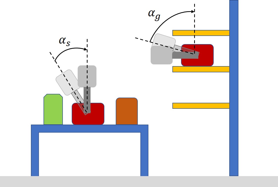
In this paper the problem of shelf replenishment in supermarkets is investigated in the context of the REFILLS project [4]. This scenario poses new challenges in addition to those seen in the APC. Robots will need a large skill set to execute fetch and place tasks in this environment because they have to operate in tight spaces and handle a variety of objects. This skill set has to include in-hand manipulation to, at least, avoid time-consuming re-grasping. An example is depicted in Fig. 1. Suppose that the robot has to pick the red object in the center of the table to place it in the middle shelf layer in the goal pose on the right side of the drawing. Clearly, there is no fixed grasp with a gripper pose that is reachable and collision free for both pick and place poses. With a standard planning process [5] only a re-grasp action executed on a buffer tray could allow the robot to execute the task. However, with the ability to perform a controlled rotational sliding of the object by rotating the gripper while keeping the object fixed (the so-called gripper pivoting), the planner has a bigger search space and will likely find a feasible path.
Recent papers dealing with in-hand manipulation are [6] and [7]. The first one solves the planar pushing problem by making use of the differential flatness concept and the feedback linearization technique. The second one deals with the same application but focuses on planning pushing trajectories based on the concept of motion cones. However, open loop approaches, by definition do not react to perception feedback. Sensor-based control is required to robustly execute the plan in the uncertain world. In the past we have worked on a controller that can be parameterized to switch between slipping avoidance and controlled rotational slippage of held objects [8]. Improvement of robot dexterity is achieved through smart control of the grasping rather than using additional degrees of freedom, according to the well-known concept of the extrinsic dexterity [9]. It demonstrated to be reliable enough to handle a good variety of objects. A review of alternative approaches can be found here [10].
However, this, on its own, is just one of the aforementioned skills that a robot will need. To use this new potential with a higher degree of autonomy, it has to be combined with a motion planner that has the ability to utilize it.
In the REFILLS project, a knowledge-enabled and plan-based control architecture, i.e., the competent selection and execution of plans from a plan library, inspired by [11], is ultimately desired. Winkler et al. [12] have already demonstrated successfully that the paradigm of knowledge-enabled and plan-based control is well suited for robotic shelf replenishment tasks in retail environments.
The main contribution of this paper is a method to achieve a close integration of the low-level reactive control layer with the motion planner, which is a building block of the REFILLS architecture. The focus is on the fetch and place phase of the shelf replenishment task, where a large variety of objects have to be handled safely, i.e., fetched and placed on a shelf with a specific pose, potentially different from the grasp pose, while avoiding object slipping. The method relies on the capability, offered to the motion planner by the in-hand manipulation abilities of the grasp controller, to change the kinematic model of the robot to enlarge the search space, and thus making it more likely find a solution.
In addition to this, we contribute an improved version of a force/tactile sensor [13] that is used with the reactive control algorithm. The sensor has been integrated onto the fingers of a commercial gripper and has dimensions suitable to enter the narrow spaces between objects on a shelf. The PCB design has been improved to enhance the signal-to-noise ratio through current feeding of LED’s, the use of analogue buffers to interface the voltage signals to the A/D converters and the integration on board of a microcontroller with several possibilities for communication interfaces.
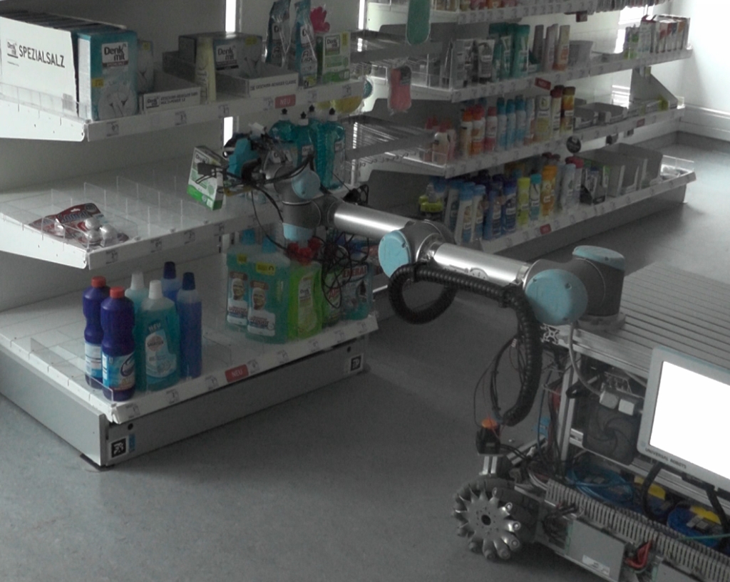
Experiments will demonstrate how manipulation tasks necessary for shelf replenishment, while unfeasible with a fixed grasp, become feasible by using the additional dexterity provided by the slipping control. The experiments were performed on a mobile manipulator (see Fig. 2). It is equipped with a gripper sensorized with force/tactile sensors (see Fig. 4, but the cameras were not used in this paper). The five objects shown in Fig. 7 are used in the experimental trials.
II The Sensing Apparatus
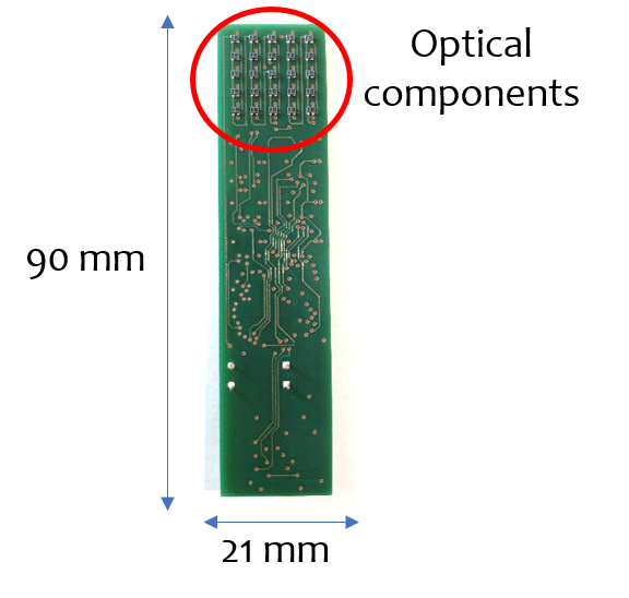
The sensorized fingers used in this work are based on the technology originally presented in [14]. The developed tactile sensors are mainly constituted by three components: a Printed Circuit Board (PCB), a rigid grid and a deformable pad. A preliminary design of these tactile sensors was presented in [13]. The main differences with respect to the version used in this paper concern the Printed Circuit Board (PCB) design.
The PCB design
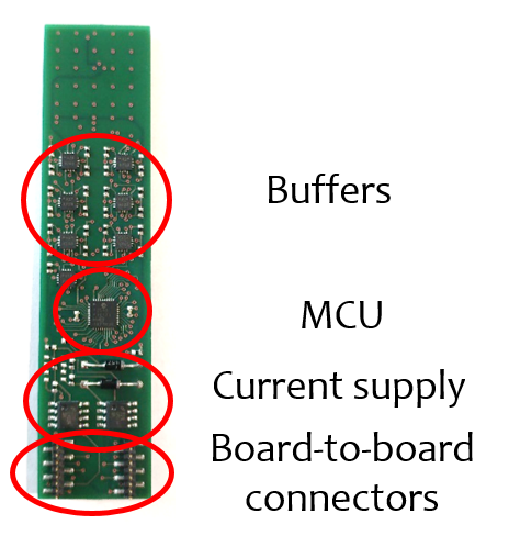
A different version of the PCB has been designed to improve the following aspects. Each sensible point, called taxel, on the PCB is constituted by a photo-reflector, manufactured by New Japan Radio (code NJL5908AR). The PCB integrates taxels, organized in a matrix, with a spatial resolution of mm. In previous versions the LEDs of photo-reflectors were driven with a voltage supply and a series resistance. In this case the LEDs are driven with adjustable current sources (manufacturer code LM334) to improve the stability of the emitted light, by reducing its temperature drift. Additionally, in order to enhance the signal-to-noise ratio and simplify the interrogation firmware, further improvements have been introduced:
-
•
Analogue buffers (realized by using the low-power operational amplifiers ADA4691) to decouple the photo-reflector output signals from the A/D acquisition stage.
-
•
Monolithic microcontroller with 12-bit A/D channels instead of separate A/D converters with SPI interface.
-
•
Microcontroller integrated into a single PCB together with the other components.
This solution allows avoiding the use of the additional SPI interface, thus obtaining a fully integrated sensor with a programmable device usable for sensor data acquisition via different interfaces. In this paper a standard serial interface has been exploited through a USB-to-serial commercial cable. The resulting sampling frequency for all sensor data is Hz. Figure 3 reports some pictures of the re-designed and assembled PCB.
The rigid grid
The grid frame has been slightly modified to perfectly align the mechanical part with the PCB and the taxels, without using the rigid pins used in the previous version. The grid is hence bonded to the PCB with a cyanoacrylate-based glue.
The deformable pad
It has the role to transduce the applied forces into deformations that can be detected by the taxels. It has been realized with the same dimensions, material and molding procedure detailed in [13].
The assembled force/tactile sensor is fixed inside a case designed to house the sensor and for installation on the WSG-series flange.

III Implementation And Architecture
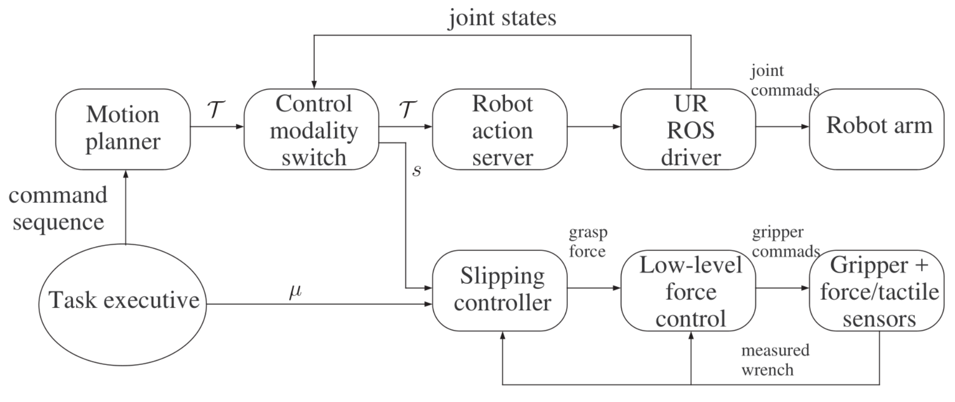
In this section we present the architecture of the integrated system, depicted in Figure 5. The task executive sends goals to the motion planner, that are needed to achieve tasks such as replenishing a shelf. This module has access to a knowledge base and sets the friction coefficient , an object specific parameter for the slipping controller.
The motion planner generates joint space trajectories that achieve the given goals while utilizing the robots’ ability to pivot grasped objects.
The control modality switch module post-processes the trajectory, before sending it to the robot. While the trajectory is executed, the module sends commands to the slipping controller to switch between the two control modalities.
In the following subsections we detail the slipping controller, the changes to the motion planner and the control modality switch. The task executive is omitted, because it is a simple sequence of motion goals in our experiments.
III-A Slipping Controller
The slipping control algorithm used is originally described in [8] and generalized in [10], where the grasp control action is based on the estimated slipping velocity of the object. It exploits the Limit Surface (LS) theory [15] that describes the translational and rotational slippage at the same time. The algorithm will be briefly described in this section but the interested reader can find more details in [8] and [10].
The aim of the algorithm is to provide the minimum grasp force (the component normal to the contact area) that keeps the object inside the fingers without slippage. The approach is model-based and needs few parameters of the LS such as the friction coefficient and two additional parameters that depend on the material of the sensor soft pad and which can be identified with a simple experimental procedure in the sensor calibration phase. Therefore, only the friction coefficient is object dependent and has to be changed as soon as a new object is being handled. The friction coefficient of new objects can be easily estimated by following the experimental procedure described in [16], which consists in rubbing the surface of the object. The algorithm uses the frictional tangential force and torsional moment provided by the sensorized fingers to compute the needed grasp force according to the LS model. The assumptions are: the object is grasped by a parallel gripper; the faces of the object in contact with the fingers are flat and rigid compared to the fingertips so that the object can be treated as a planar slider.
It is possible to distinguish two control modalities. The first modality is the slipping avoidance that considers the whole wrench to compute the grasp force to avoid both translational and rotational slippage. This force is the superposition of two components: a first component, called static, that uses only the LS model and is useful when the variation rate of the forces is slow; a second component, called dynamic, that exploits a Kalman filter and is useful in the case of a fast force variation rate. The symbol will be used to indicate the grasp force computed by this control modality. The second modality is the gripper pivoting. In this modality, the same slipping avoidance algorithm is used with no dynamic component and without considering the measured torque, i.e., using a zero torque as input of the algorithm. The resulting grasp force is enough to avoid the translational slippage but not the rotational one. The symbol will be used to indicate the grasp force computed by this control modality. During the gripper pivoting, the object behaves like a pendulum and stays in its equilibrium orientation, i.e., the vector pointing from the grasp point to the center of gravity (CoG) is aligned with gravity. Moreover, the grasp point is important. If it is not above the CoG, the object will rotate so that the CoG goes to the equilibrium point below the grasp point. Furthermore, the grasp point cannot be on the CoG because the gravitational torque would be zero, making pivoting impossible. Therefore, we assume to know the CoG of the object, which is another physical parameter that has to be estimated with an exploration procedure. Once the friction coefficient has been estimated, the object can be firmly grasped and the CoG position with respect to the grasp point can be easily obtained from the measured wrench by changing the gripper orientation.
III-B Motion Planner
We intend to model the pivoting functionality by connecting the grasped object via a constrained virtual joint to the robot. A constraint sampling based planner [17] or trajectory optimization [18][19] are standard choices. However, these approaches don’t scale well with constraints that are too restricting. The motion planner used in [20] is well suited for this scenario, because, generally, only the number of constraints influences the run time. It is based on the eTaSL language and the eTC Controller from [21]. With this framework, motions are specified as a composition of constraints on joint velocities. We control the arm and base simultaneously. The base is modelled with two translational joints and one rotational joint, representing its pose relative to the map reference frame, giving the robot a total of 9 degrees of freedom. The framework generates joint trajectories for the whole body, which are executed in an open loop.
The gripper pivoting functionality is modelled as a virtual continuous rotational joint between the fingertips and the grasped object, thus adding an additional degree of freedom. During planning, we simulate the pivoting mode by adding a high priority constraint to all goals that minimizes the angle between the gravity vector and the vector pointing from the grasp point to the center of mass of the object :
As a result, the grasped object is always vertical during the planning process. If the planner receives Cartesian goals for the grasped object, it will change the angle between the object and gripper to avoid collisions, while keeping the object vertical. If a specific angle is required, an additional constraint on the joint position of the virtual joint can be added. The motion planner avoids self and external collisions for all robot links, grasped objects and environment objects known to the motion planner. For this paper we assume that the shelf positions are known.
For comparison, these motion planning problems have about 100 constraints. Most of them are used for collision avoidance and the exact number depends on how many objects are close to the robot. To model the gripper pivoting, we need an additional free variable for the new joint as well as one constraint to enforce the vertical orientation.
III-C Control Modality Switch
When the gripper pivoting is active, the grasp force is low. To improve robustness, the gripper pivoting mode should only be active when needed. Thus, we implemented a ROS node that switches to the slipping avoidance mode during periods of the planned motion where the virtual joint is not used.
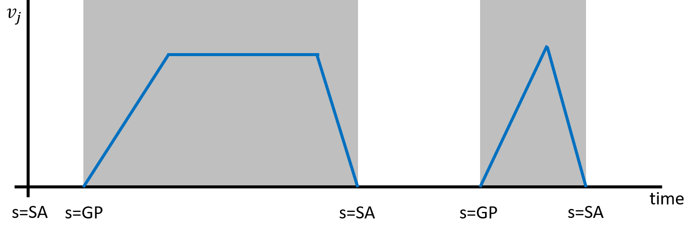
This node checks the velocity of the virtual joint against a threshold of rad/s, selected to avoid switches due to numerical noise, and stores switching events with timestamps in a vector. A velocity below the threshold requires slipping avoidance, otherwise the gripper pivoting is needed. The threshold generates a pivoting angle error smaller than the error due to the CoG position estimation; however, this error is recovered as soon as a new pivoting is triggered. The trajectory is then sent to the robot and the control modality switch starts listening to its joint states. At each modality switch event, the node sends the corresponding command to the slipping controller. Figure 6 shows a conceptual example, is the planned velocity of the virtual joint, SA and GP indicate activation timestamps of slipping avoidance and gripper pivoting, respectively. In every plot of this paper, a gray area indicates the time interval where the gripper pivoting mode is active.
IV Experimental Evaluation
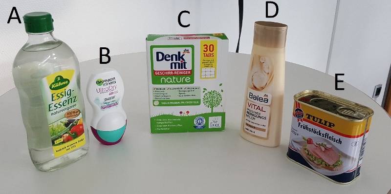
This section describes the experimental evaluation done with the objects of Fig. 7. Three sets of experiments are described. The first evaluates the angle of the object during the pivoting; the second evaluates the feasibility of a simple pick-and-place task with and without the pivoting; the third is a complete pick-and-place experiment with different objects and obstacles.
IV-A Stability Experiment
In the first experiment we investigate the reliability of both slipping avoidance and gripper pivoting algorithms by performing motions while an object is being grasped. For the tests we used object E and placed into the gripper by hand. The initial angle between the object and the fingers was measured using a manual digital inclinometer. The angle ranged from rad to rad. The robot was then commanded to execute simple motions along and about the three axes of the tool frame. During all experiments, the modality switch is active. This means that the gripper pivoting mode is automatically activated only during the rotation about the pivot axis; all other motions are executed in the slipping avoidance mode.
The experiment was repeated 12 times, six with low acceleration and six with high acceleration. Afterwards, the final angle was measured again.
| Slow Motion | Fast Motion | |
|---|---|---|
| Mean Deviation | 0.104 rad | 0.112 rad |
| Maximum Deviation | 0.181 rad | 0.194 rad |
Results are shown in Table I. Some slippage is unavoidable because of noise and uncertain contact model. The robot never dropped the item, showing both that the modality switch occurs at the right time and that the slipping avoidance is effective. Deviations lower than rad are acceptable for a large class of objects, while they are critical for thin objects that easily fall over.
IV-B Desk Experiment
With this experiment we test the interplay between the motion planner and modality switch in simple pick-and-place task using fixed and non-fixed start/goal angles. The task consists of placing the object E of Fig. 7 on a desk by picking it from the floor with a given angle between the finger approach axis and the vertical direction. The experiment is first executed in a simulated environment using different desk heights and then on the real robot using a m high desk.
| 0.0 | (-0.78) | |||||
|---|---|---|---|---|---|---|
| - | - | - | - | - | - | |
| 14.3 | 12 | 11.1 | 12.4 | - | 11.9 | |
| 0.0 | 11.8 | 10.4 | 9.1 | 10.4 | - | 10.1 |
| 13.8 | 12.5 | 10.4 | 11.8 | - | 12.2 | |
| - | - | - | - | - | - | |
| (0.35) | 12.1 | 9.9 | 9.3 | 10 | - | 9.9 |
Table II shows the results for a m desk height in the simulated environment. Various experiments have been carried out with different start and goal angles. The values inside show the planning time measured in seconds. No value indicates that the motion planner was not able to find a solution. The last row and the last column are a special case: the start and/or goal angle is not specified and the planner is free to choose the angle, the value in parentheses is the angle chosen by the planner. Note that the values on the diagonal (except the last one) are equivalent to not using the gripper pivoting functionality because the start and goal angles are the same. The planner fails to find a solution in the first and the fifth rows because the robot is not able to grasp the object on the floor with these initial angles. The same happens in the case of the fifth column, because the robot is not able to place the object on the desk with that angle. From the difference between the gray and non gray cells, we can see that the added constraint and new free variable do not significantly increase the planning time. Instead, there is a high correlation between the planning time and length of the final trajectory. This explains why the cases where both angles are chosen by the motion planner are among the fastest.
| 0.0 | (-1.76) | |||||
|---|---|---|---|---|---|---|
| - | - | - | - | - | - | |
| - | - | - | - | - | 17.9 | |
| 0.0 | - | - | - | - | - | 16.7 |
| - | - | - | - | - | 18.1 | |
| - | - | - | - | - | - | |
| (0.35) | - | - | - | - | - | 17 |
Table III shows the results for a m desk height in the simulated environment. In this case no solution with fixed angles exists. The planner was able to find a solution only for a free goal angle (last column). No solution was found in the first and the fifth elements of the last column for the same reason as the previous case.
The experiment is finally executed on the real robot with a m desk height. The results are shown in Tab. IV. Figure 8 shows a case in which the start and goal angles are the same, thus no pivoting is needed. The top plot shows the grasp force computed by the slipping avoidance algorithm , the grasp force needed for the gripper pivoting and the actuated measured grasp force . The bottom plot shows the velocity of the virtual joint . Note that in this case no gripper pivoting is needed because the velocity is almost zero, thus follows and not . In the last part of the plot, around s, the forces drop because the object is released.
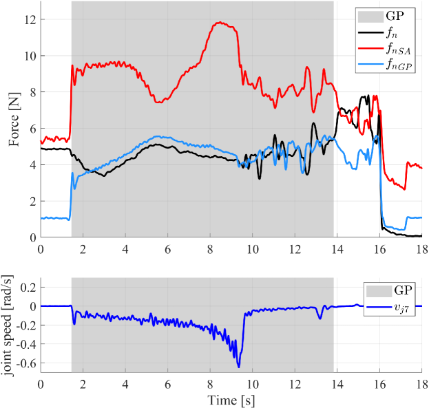
Figure 9 shows the case in which the planner automatically chose the start and goal angles. In this case, the velocity of the virtual joint is different from zero and the pivoting is needed. The gray area highlights the time interval when the gripper pivoting is active, and in this case follows .
| 0.0 | (-1.38) | |||||
|---|---|---|---|---|---|---|
| - | - | - | - | - | - | |
| 12.8 | 13.5 | 14 | - | - | 13.5 | |
| 0.0 | 11 | 11.8 | 12.6 | - | - | 12 |
| 13.9 | 14.2 | 13.9 | - | - | 13.6 | |
| - | - | - | - | - | - | |
| (0.35) | 11.3 | 11.7 | 12.1 | - | - | 11.6 |
IV-C Shelf Experiment
| shelf at 0.2m | shelf at 0.6m | shelf at 0.93m | shelf at 1.31m | |||||||||
|---|---|---|---|---|---|---|---|---|---|---|---|---|
| (-0.95) | (-1.38) | (-1.58) | (-1.82) | |||||||||
| 20.5 | 18.3 | 22.1 | 17.7 | - | 18.9 | - | 22.5 | 21.5 | - | - | 25.5 | |
| 0.0 | 23.5 | 19 | 21.1 | 18.5 | - | 17.9 | 20.8 | 21.7 | 19.9 | - | - | 24.1 |
| (0.16) | 23.2 | 19.7 | 22.3 | 17.1 | - | 18.7 | 20.2 | 21.7 | 21.1 | - | - | 25.5 |
In the last experiment, we test the whole algorithm in a complex real case scenario where the gripper pivoting ability may be mandatory due to obstacle positions.
We consider a shelf replenishment task: objects A-D, depicted in Fig. 7, were chosen for their variety in weight and surface properties and are picked up from the floor and placed on different layers on a shelf system. The experiment is first executed in simulation. The same combinations of start and goal angles as in the previous experiment are tested, but the proximity of shelves greatly decreases the number of possible goal angles. The results are shown in Table V. Rows and columns that failed for all shelves are omitted to save space. The gripper pivoting proves very useful in this scenario, because the planner only found solutions for fixed angles on two shelves and only for one angle. On the shelf at height m, the shelf above is too close and the shelf at is too high for that configuration.
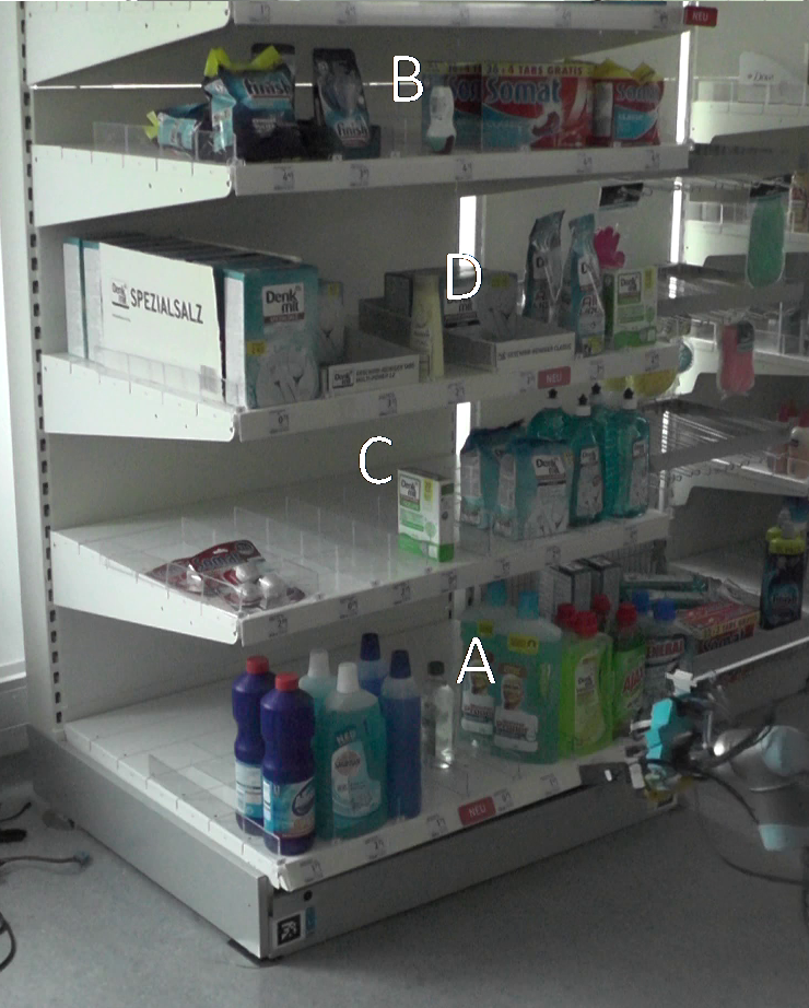
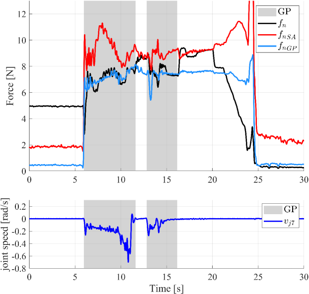
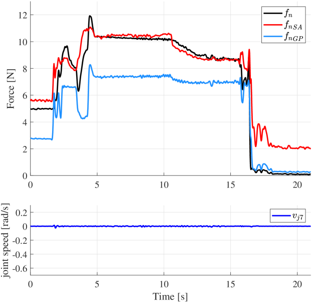
The experiment is executed on the real robot for the case of free start and goal angles and can be seen in the accompanying video. Fig. 10 shows the shelf filled at the end of the experiment. Fig. 11 shows a plot of the forces and virtual joint speed when object A is placed on the bottom shelf. The start and goal angles chosen by the planner are rad and rad respectively. In the figure as well as the video it is clear that the pivoting is activated in two phases, after the lift to reach the shelf and inside the shelf to avoid collisions.
IV-D Sensitivity Experiment
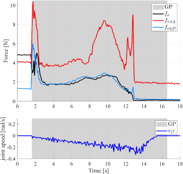
To assess the sensitivity of the algorithm to the friction coefficient, the last experiment has been repeated with different values of . In particular, for object B, instead of the estimated value , an underestimated one has been used, i.e., (that means about ). The result is a failure of the task because the gripper pivoting was not executed properly, such that the object did not rotate and fell over. Values higher than did not result in a failure. That means that the pivoting algorithm is quite robust against underestimated values for , at least when the effect of the torsional moment dominates the effect of the tangential force, i.e., when the grasp point is far from the CoG, as for object B. Finally, the placing of object D was repeated with . That equals a overestimation with respect to , which was estimated for that object. This resulted in a grasping force that was too low, making the object slip out of the fingers. This can be deduced by Fig. 12, where the grasp force suddenly goes to zero at about s. Both failures are reported in the accompanying video.
V Conclusion
This paper shows how a tight integration of grasping control with a motion planner allows a mobile manipulator to solve complex manipulation tasks in a realistic logistic scenario. In-hand manipulation abilities provided by the low-level slipping control layer are exploited by the planning algorithm to solve fetch and place tasks in confined spaces. This has been achieved by a novel switching method between two different grasp control modalities: slipping avoidance and gripper pivoting. Gripper pivoting allows the robot to change the grasp configuration without re-grasping the object, effectively adding a degree of freedom. The slipping controller needs an object specific friction parameter to work, which is currently estimated in advance and saved in a knowledge base. In the future, we plan to integrate this into a knowledge-enabled and plan-based control architecture proposed for the REFILLS project to autonomously replenish shelves in supermarkets. Then, we desire an autonomous estimation of the object specific friction parameter through tactile exploration of unknown objects.
References
- [1] “Amazon picking challenge,” http://amazonpickingchallenge.org/how-much-has-amazon-invested-in-automation/, accessed: 2019-08-31.
- [2] A. Zeng, S. Song, K. Yu, E. Donlon, F. R. Hogan, M. Bauza, D. Ma, O. Taylor, M. Liu, E. Romo, N. Fazeli, F. Alet, N. C. Dafle, R. Holladay, I. Morena, P. Qu Nair, D. Green, I. Taylor, W. Liu, T. Funkhouser, A. Rodriguez, “Robotic Pick-and-Place of Novel Objects in Clutter with Multi-Affordance Grasping and Cross-Domain Image Matching,” in 2018 IEEE Int. Conf. on Robotics and Automation, May 2018, pp. 3750–3757.
- [3] N. Correll and K. E. Bekris and D. Berenson and O. Brock and A. Causo and K. Hauser and K. Okada and A. Rodriguez and J. M. Romano and P. R. Wurman, “Analysis and Observations From the First Amazon Picking Challenge,” IEEE Transactions on Automation Science and Engineering, vol. 15, no. 1, pp. 172–188, Jan 2018.
- [4] “Refills project,” http://www.refills-project.eu, accessed: 2019-09-01.
- [5] S. Chitta and I. Sucan and S. Cousins, “MoveIt! [ROS Topics],” IEEE Robotics Automation Magazine, vol. 19, no. 1, pp. 18–19, March 2012.
- [6] J. Zhou, Y. Hou and M.T. Mason, “Pushing revisited: Differential flatness, trajectory planning, and stabilization,” The International Journal of Robotics Research, vol. 38, no. 12-13, pp. 1477–1489, 2019.
- [7] N. Chavan-Dafle, R. Holladay and A. Rodriguez, “Planar in-hand manipulation via motion cones,” The International Journal of Robotics Research, pp. 1–20, 2019.
- [8] M. Costanzo, G. De Maria, and C. Natale, “Slipping control algorithms for object manipulation with sensorized parallel grippers,” in 2018 IEEE International Conference on Robotics and Automation (ICRA), May 2018, pp. 7455–7461.
- [9] N. Dafle, A. Rodriguez, R. Paolini, B. Tang, S. Srinivasa, M. Erdmann, M. Mason, I. Lundberg, H. Staab, and T. Fuhlbrigge, “Extrinsic dexterity: In-hand manipulation with external forces,” in 2014 IEEE Int. Conf. on Robotics and Automation, Hong Kong, 2014, pp. 1578–1585.
- [10] M. Costanzo, G. De Maria and C. Natale, “Two-Fingered In-Hand Object Handling Based on Force/Tactile Feedback,” IEEE Trans. on Robotics, pp. 1–17, 2019.
- [11] M. Beetz, D. Jain, L. Mösenlechner, M. Tenorth, L. Kunze, N. Blodow, and D. Pangercic, “Cognition-enabled autonomous robot control for the realization of home chore task intelligence,” Proceedings of the IEEE, vol. 100, no. 8, pp. 2454 – 2471, 2012.
- [12] J. Winkler, F. Balint-Benczedi, T. Wiedemeyer, M. Beetz, N. Vaskevicius, C.A. Mueller, T. Fromm, A. Birk, “Knowledge-enabled robotic agents for shelf replenishment in cluttered retail environments,” in 2016 Int. Conf. on Autonomous Agents & Multiagent Systems, 2016, pp. 1421–1422.
- [13] M. Costanzo, G. De Maria, C. Natale, and S. Pirozzi, “Design and calibration of a force/tactile sensor for dexterous manipulation,” Sensors - MDPI, vol. 19, no. 4, pp. 1 – 23, 2019.
- [14] G. De Maria, C. Natale, and S. Pirozzi, “Force/tactile sensor for robotic applications,” Sensors and Actuators A: Physical, vol. 175, pp. 60 – 72, 2012.
- [15] S. Goyal, A. Ruina, and J. Papadopoulos, “Planar sliding with dry friction part 1. limit surface and moment function,” Wear, vol. 143, no. 2, pp. 307 – 330, 1991.
- [16] A. Cirillo, P. Cirillo, G. De Maria, C. Natale, S. Pirozzi, “Control of linear and rotational slippage based on six-axis force/tactile sensor,” in 2017 IEEE Int. Conf. on Robotics and Automation, May 2017, pp. 1587–1594.
- [17] D. Berenson, S. Srinivasa, D. Ferguson, J.J. Kuffner, “Manipulation planning on constraint manifolds,” in 2009 IEEE International Conference on Robotics and Automation. IEEE, 2009, pp. 625–632.
- [18] M. Toussaint, “Robot trajectory optimization using approximate inference,” in Proceedings of the 26th annual international conference on machine learning. ACM, 2009, pp. 1049–1056.
- [19] A.D. Dragan, N.D. Ratliff, S.S. Srinivasa, “Manipulation planning with goal sets using constrained trajectory optimization,” in 2011 IEEE Int. Conf. on Robotics and Automation, 2011, pp. 4582–4588.
- [20] Z. Fang, G. Bartels, and M. Beetz, “Learning models for constraint-based motion parameterization from interactive physics-based simulation,” in 2016 IEEE/RSJ Int. Conf. on Intelligent Robots and Systems. IEEE, 2016, pp. 4005–4012.
- [21] E. Aertbeliën and J. De Schutter, “etasl/etc: A constraint-based task specification language and robot controller using expression graphs,” in 2014 IEEE/RSJ International Conference on Intelligent Robots and Systems. IEEE, 2014, pp. 1540–1546.