A Conceptual Design Study of a Compact Photon Source (CPS) for Jefferson Lab
Abstract
This document describes the technical design concept of a compact high intensity, multi-GeV photon source. Capable of producing 1012 equivalent photons per second this novel device will provide unprecedented access to physics processes with very small scattering probabilities such as hard exclusive reactions on the nucleon. When combined with dynamic nuclear polarized targets, its deployment will result in a large gain in polarized experiment figure-of-merit compared to all previous measurements. Compared to a traditional bremsstrahlung photon source the proposed concept presents several advantages, most significantly in providing a full intensity in a small spot at the target and in taking advantage of the narrow angular spread associated with high energy bremsstrahlung compare to the wide angular distribution of the secondary radiation to minimize the operational prompt and activation radiation dose rates.
I Introduction
A quantitative description of the nature of strongly bound systems is of great importance for an improved understanding of the fundamental structure and origin of matter. One of the most promising ways to access information on the dynamical structure of the nucleon is through exclusive reactions at high momentum transfer, in which the deep interior of the nucleon is probed with a highly-energetic photon or electron probe and all final-state particles are detected Hand63 ; Kugler71 . Even though the scattering probability of such reactions is extremely small it has become clear that such reactions offer a promising route to imaging of the elusive 3-D nucleon substructure. Indeed, there have been increasingly sophisticated theoretical efforts to exploit the richness of exclusive reactions at short resolution scales Goeke01 .
Exclusive measurements with high-energy electron and photon beams form the core of the new paradigm within sub-atomic science termed ”nuclear femtography”. In both photon and electron scattering experiments, the scale of the associated imaging that can be performed is set by the invariant squared four-momentum transferred to the proton target, , and the total centre-of-mass energy squared, . Measurements over a wide range of and with these probes allow for the disentangling of four functions representing the vector, axial, tensor, and pseudo-scalar response of the nucleon. Simultaneous experimental access to all of these functions is most readily achieved with a spin polarized nuclear or nucleon target.
Much progress imaging nucleon structure can be made with electron-scattering reactions, yet experiments utilizing high-energy photons play a unique complementary role. Measurements involving the small scattering probabilities associated with exclusive reactions demand high-intensity photon beams. Further, our basic understanding will be much strengthened by imaging longitudinally-polarized and transversely-polarized nucleons. It is for this combination that the proposed concept is primarily focused: with a newly-developed compact photon source (CPS) SABW2014 ; BWGN2015 and a dynamically-nuclear polarized target system, for example in Hall C at Jefferson Lab, a gain of a factor of 30 in the figure-of-merit (as defined by the photon intensity and the average target polarization over the experiment) can be achieved. The net gain makes it possible to measure the very small scattering cross sections associated with a new suite of high-energy photon scattering experiments to image and understand the dynamical nucleon structure CPSWS .
The concept of a CPS also enables other science possibilities, like enriching the hadron spectroscopy program in Hall D at Jefferson Lab and at other facilities. Hall D is a newly-built experimental hall, with a large acceptance spectrometer and a tagged, linearly polarized photon beam of low to moderate intensity. The addition of a CPS to this hall opens the door to increased sensitivity to rare processes through a higher intensity photon beam or the production of secondary beams of other particles, such as a beam Klong . Although there are fewer physical limitations on the size of the CPS in Hall D, allowing for additional flexibility in the optimization of the shielding, most of the other requirements are similar to CPS running in the other halls. The radiation shielding requirements are similar in order to ensure safe operation and to prevent radiation damage to the tagger detectors and their associated electronics located upstream of the planned CPS location.
For operation of the proposed facility, the electron beam has been proposed to have a power up to 60kW, running at an energy of 12 GeV with a 64 ns beam bunch spacing. Initial estimates suggest that the default CPS configuration can handle the power deposition, and sufficient cooling water is available, as the electron dump for the nominal Hall D photon beam is designed to absorb at least 60 kW of power. A major difference, as compared to Hall C, is that the Hall D CPS is located in a separate section of the hall from the target and main spectrometer, and is separated by m of pipe under vacuum surrounded by soil. The size of the photon beam generated by the CPS is dominated by multiple scattering in the radiator, and has estimated to be 2 cm after traveling 80 m. This is well within the size of the 15 cm-diameter beam pipe, and the 6 cm-diameter Be target. Finally, if the CPS radiator is retracted, then the current Hall D photon beam can be used without moving the CPS or any other modification from the beamline. Taking all of these factors into account, the CPS design is well matched for experiments in Hall D requiring a high-intensity untagged photon beam.
II Science Opportunities with CPS
Investigating the three-dimensional structure of the nucleon has historically been an active and productive field of research, especially so during the last two decades since the invention of the generalized parton distributions (GPD) formalism. Research focused on this three-dimensional structure continues to be central to the hadron physics program at facilities like Jefferson Lab. The GPD formalism provides a unified description of many important reactions including elastic electron scattering, deep-inelastic scattering (DIS), deeply-virtual and timelike Compton scattering (DVCS and TCS), deeply-virtual meson production (DVMP), and wide-angle real Compton scattering (RCS) and meson production. All of these can be described by a single set of four functions , , and , which need to be modeled and constrained with parameters extracted from experimental data Diehl03 ; Burkardt02 ; Goeke01 ; Belitsky05 ; Ji97 ; Radyushkin96 ; Mueller94 ; Collins97 ; Collins99 . The CPS science program as proposed for Jefferson Lab enables studies of the three-dimensional structure of the nucleon and features one fully approved and two conditionally approved experiments Klong ; E12-17-008 ; C12-18-005 .
Jefferson Lab Experiment E12-17-008 E12-17-008 will measure polarization observables in real Compton scattering (RCS). This is a fundamental and basic process, yet its mechanism in the center-of-mass energy regime of = 5-10 GeV remains poorly understood. Measurements show that these data cannot be described by perturbative calculations involving the scattering of three valence quarks. Rather the dominant mechanism is the so-called ”handbag model” where the photon scatters from a single active quark and the coupling of this struck quark to the spectator system is described by GPDs Rad98 ; Diehl99 . It is this latter conceptual mechanism that lies at the root of the worldwide efforts of 3D (spatial) imaging of the proton’s quark-gluon substructure, as the GPDs contain information about the transverse spatial distribution of quarks and their longitudinal momenta inside the proton.
The RCS experimental observables provide several constraints for GPDs which are complementary to other exclusive reactions due to an factor and an additional weighting in the corresponding GPD integrals. For example, the elastic form factor is related to the RCS vector form factor , both of which are based on the same underlying GPD . Similarly, polarized observables in
RCS uniquely provide high constraints on via extraction of the RCS axial form factor in a kinematic regime where precise data on the nucleon axial form factor is not available Kroll17 ; Kroll18 . A measurement of the spin asymmetry in RCS with the proton target longitudinally polarized can further disentangle the various reaction mechanism models. If consistent with the measurement of the spin transfer from the photon to the scattered proton, the asymmetry can be surprisingly large and stable with respect to the photon center-of-mass scattering angle. Investigations into the mechanisms behind RCS will provide crucial insight into the nature of exclusive reactions and proton structure and are ideally suited for the facilities provided by the Jefferson Lab 12-GeV upgrade Dudek12 ; NPSWP14 ; DOE15 ; Mont17 .
Jefferson Lab Experiment C12-18-005 C12-18-005 will probe 3D nucleon structure through timelike Compton scattering, where a real photon is scattered off a quark in the proton and a high-mass (virtual) photon is emitted, which then decays into a lepton pair Berger02 ; Anikin18 . Using a transversely polarized proton target and a circularly polarized photon beam allows access to several independent observables, directly sensitive to the GPDs, and in particular the GPD which is poorly constrained and of great interest due to its relation to the orbital momentum of the quarks Kroll10 ; Kroll11 ; Gold12 . The experiment involves measurements of the unpolarized scattering probabilities or cross section, the cross section using a circularly polarized photon beam, and the cross section using transversely-polarized protons. This will provide a first fundamental test of the universality of the GPDs, as the GPDs extracted from TCS should be comparable with those extracted from the analogous spacelike (electron) scattering process – deeply virtual Compton scattering, a flagship program of the 12-GeV Jefferson Lab upgrade Dudek12 ; NPSWP14 ; DOE15 ; Mont17 .
A separate window on the nature of strongly bound systems is provided through the hadron spectrum. The spectrum allows study of the properties of QCD in its domain of strong-coupling, leading to the most striking feature of QCD: the confinement of quarks and gluons within hadrons: mesons and baryons. Experimental investigation of the baryon spectrum provides one obvious avenue to understand QCD in this region since the location and properties of the excited states depend on the confining interaction and the relevant degrees of freedom of hadrons.
Understanding the constituent degrees of freedom in hadrons requires identifying a spectrum of states and studying their relationships, both between states with the same quark content but different quantum numbers, and vice versa. The hadrons containing strange quarks are particularly interesting to study because they lie in a middle ground between the nearly massless up & down quarks and the heavy charm & bottom quarks, and while a rich spectrum of strange quark hadrons is predicted comparatively very little is known about them. Over the past two decades, meson photo- and electroproduction data of unprecedented quality and quantity have been measured at facilities worldwide, leading to a revolution in our understanding of baryons consisting of the lightest quarks, while the corresponding meson beam data are mostly outdated or non-existent meson_beams . For the study of strange quark hadrons, a kaon beam KL2016_proc has the advantage over photon or pions beams of having strange quarks in the initial state, which leads to enhanced production of these states. A secondary beam provides a unique probe for such studies, and by using a primary high intensity photon beam, a high-quality beam with low neutron background can be generated. In conjunction with a large acceptance spectrometer, this enables the measurement of cross sections and polarizations of a range of hyperon production reactions, and allows for the identification of the quantum numbers of identified states and provides the opportunity to make a similar leap forward in our understanding of the strange hadron spectrum. The study of strange hadron spectroscopy using an intense beam is the topic of Jefferson Lab Experiment C12-19-001 Klong .
III Science Method
One of the traditional experimental techniques for producing a beam of high-energy photons is to allow an electron beam to strike a radiator, most commonly copper, producing a cone of bremsstrahlung photons which are consequently mixed with the electron beam (see Fig. 1a). The spread in the photon and outgoing electron beams is dominated by electron multiple scattering, and for electron beam energies of a few GeV is typically less than 1 mrad. Accompanying this mixed photon and electron beam are secondary particles produced in the electron-nuclei shower and characterized by a much larger angular distribution (the extent of these secondary cones are highlighted in the figure). For example, the cone of secondary particles that survive filtering through a heavy absorber material of one nuclear interaction length (140-190 g/cm2 or 15 cm) has an angular spread of 100-1000 mrad. Although this is the preferred technique for producing the largest flux of photons, drawbacks include the fact that the beam is a mix of both photons and electrons, that the photon beam energy is not a priori known, and that the method is accompanied by the potential for large radiation background dose due to the large spread of secondary particles produced.
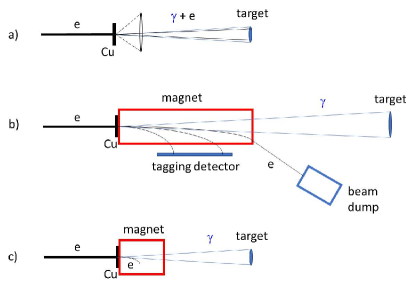
An alternative technique for producing a photon beam involves the use of a radiator, a deflection magnet and a beam dump for the undeflected electrons, augmented for energy-tagged photon beams with a set of focal plane detectors covering a modest to large momentum acceptance (see Fig. 1b). A configuration like this requires significant space along the beam direction and heavy shielding around the magnet and the beam dump, which have large openings due to the large angular and energy spread of the electrons after interactions in the radiator. In addition, without tight collimation the traditional scheme leads to a large transverse size of the photon beam at the target due to divergence of the photon beam and the long path from the radiator to the target. This can be an issue as the beam spot size contributes to the angular and momentum reconstruction resolution of the resultant reaction products due to uncertainty in the transverse vertex position. The advantage of this method is that one has a pure photon beam, and if augmented with a set of focal-plane tagging detectors the exact photon energies can be determined. A significant drawback is that in order to keep focal-plane detector singles rates at a manageable level (typically less than a few MHz) the flux of incident electrons must be modest ( 100 nA) and, correspondingly, the photon flux is less than might otherwise be possible.
The proposed CPS concept (see Fig. 1c) addresses the shortcomings of these two traditional widely-used experimental techniques. The concept takes advantage of the modest spread of the photon beam relative to the angular distribution of the secondary particles produced in the electron-nuclei shower. It does so by combining in a single shielded assembly all elements necessary for the production of the intense photon beam and ensures that the operational radiation dose rates around it are acceptable (see Ref. CPS-Concept ). Much of this is achieved by keeping the overall dimensions of the apparatus limited, and by careful choice and placement of materials.
The CPS conceptual design features a magnet, a central copper absorber to handle the power deposition, and tungsten powder and borated plastic to hermetically shield the induced radiation dose as close to the source as possible. The magnet acts as dump for the electrons with a cone of photons escaping through a small collimator. The size of the collimator can be chosen to be as narrow as the photon beam size, taking into account natural divergence plus the size of the electron beam raster. The concept of a combined magnet-dump allows us to reduce dramatically the magnet aperture and length, as well as the weight of the radiation shield, due to the compactness and hermeticity (with minimized openings) of the system, thus significantly reducing the radiation leakage. This conceptual approach opens a practical way forward for a CPS, providing one can manage both the radiation environment in the magnet and the power deposition density in the copper absorber.
Compared to the more traditional bremsstrahlung photon sources (Figs. 1a and 1b and e.g. Refs. Anderson1970 ; Tait1969 ), the proposed solution offers several advantages, including an intense and narrow pure photon beam and much lower radiation levels, both prompt and post-operational from radio-activation of the beam line elements. The drawbacks are a somewhat reduced photon flux as compared to the scheme of Fig. 1(a), and not having the ability to directly measure the photon energy as in the scheme of Fig. 1(b).
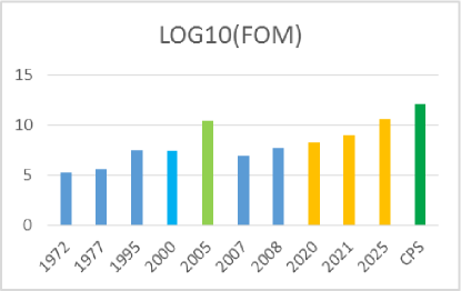
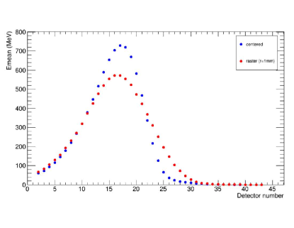
The primary gain of the CPS, and the reason for much of the initial motivation, is for experiments using dynamically nuclear polarized (DNP) targets, with an estimated gain in figure-of-merit of a factor of 30 (see Fig. 2). Dynamic nuclear polarization is an effective technique to produce polarized protons, whereby a material containing a large fraction of protons is cooled to low temperatures, 1 K, and placed in a strong magnetic field, typically about 5 Tesla Averett99 ; Pierce14 . The material is first doped, either chemically or through irradiation, to introduce free radicals (electrons). The low-temperature and high-field conditions cause the electrons to self-polarize, and their polarization is then transferred to the proton using microwave techniques. These conditions however impose a serious limitation: beams traversing the polarized target material will produce ionization energy losses that simultaneously heat and depolarize the target. They also produce other harmful free radicals which allow further pathways for proton polarization to decay. This limits the local beam intensities the polarized target material can handle.
Conventional target cells have diameters much larger than the desirable beam spot size, and one is forced to minimize rapid degradation of the target polarization by the beam at one location at the target. The traditional solution of minimizing such localized polarization degradation is fast movement of the beam spot, which allows avoiding overheating of the material and ensuring that the depolarizing effects of the beam are uniformly spread over the target volume.
A beam raster magnet, which moves the beam with a frequency of several Hz, was used in past experiments in Jefferson Lab Averett99 ; Zhu01 ; Pierce14 . However, this does not work for very small collimation apertures, e.g. a few mm by a few mm collimation cone, limiting possible beam motion. The CPS solution for the beam-target raster thus includes a combination of the target rotation around the horizontal axis and 10 mm vertical motion of the target ladder. Such a raster method effectively moves the motion complexity out of the high radiation area of the absorber. The same effect can be achieved by vertical displacement of the beam spot, i.e. by a small variation of the vertical incident angle of the electron beam at the radiator. With a 5 mrad vertical angle variation and 200 cm distance between the radiator and the target, the displacement of the beam spot is equal to 1 cm, about the size of the conventional target cells.
Traditionally, such photon beam experiments have been performed using the scheme indicated in Fig. 1a. This limits the electron beam current to less than 100 nA to prevent rapid target polarization damage. With the CPS scheme, we anticipate use of an electron beam current of up to 2.7 A to provide the photon flux for an equivalent heat load in the DNP target. Hence, we gain a factor of about 30. The history of the figure-of-merit of bremsstrahlung photon beam experiments with DNP targets is further illustrated in Fig. 2.
IV The Compact Photon Source - Description of Instrumentation
The physics program described above requires a high-intensity and narrow polarized photon beam and a polarized target to access the exclusive photoproduction reactions in order to extract the relevant experimental observables. The CPS provides a compact solution with a photon flux of equivalent photons/s.
IV.1 Conceptual Design
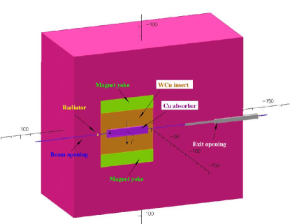
The main elements of the CPS are shown in Fig. 3. Without loss of photon intensity, a channel (a collimator for the secondary radiation) around the photon beam can be as narrow as the photon beam size. After passing through the radiator, the electron beam should be separated from the photon beam by means of deflection in a magnetic field. The length, aperture and field strength of the magnet are very different in the proposed source compared to in the traditional tagging technique. In the traditional source the magnet is needed to direct the electrons to the dump. Because of the large momentum spread of electrons which have interacted in the radiator, the magnet aperture needs to be large and the dump entrance even larger: 13% of the beam power is therefore lost before the beam dump, even with a 10% momentum acceptance of the beam line. In contrast, in the proposed source the magnet acts as dump for the electrons with a cone of photons escaping through a small collimator.
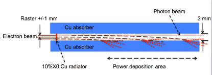
The dumping of the electron beam starts in the photon beam channel, so even a small deflection of the electron trajectory by just 1-3 mm due to the presence of the magnetic field is already sufficient to induce a shower. At the same time, such a deflection needs to be accomplished at a relatively short distance (much shorter than the size of the radiation shielding) after the beam passes through the radiator to keep the source compact. Indeed, in the proposed CPS magnet design the trajectory radius is about 10 m for 11 GeV electrons, the channel size is 0.3 cm, and the raster size is 0.2 cm, so the mean distance travelled by an electron in the magnetic field is around 17 cm, with a spread of around 12 cm (see the scheme in Fig. 4). Therefore, a total field integral of 1000 kG-cm is adequate for our case, which requires a 50 cm long iron-dominated magnet.
IV.2 Magnet
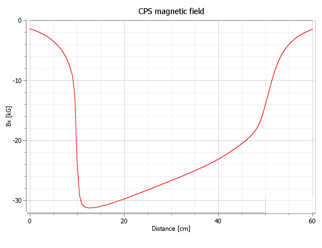
Normal conducting magnets for operation in high levels of radiation have been constructed at several hadron facilities, including the neutron spallation source at ORNL and the proton complex JPARC Tanaka11 ; Petrov16 . The magnet designed for the CPS has permendur poles tapered in two dimensions, which allows for a strong magnetic field at the upstream end of the magnet (3.2 T), with the coils located 20 cm from the source of radiation. The resulting radiation level at the coil location was calculated to be sufficiently low (below 1 Mrem/hr) to allow the use of relatively inexpensive kapton tape based insulation of the coils Kapton . As discussed above, the length of the magnet was selected to be 50 cm and the field integral 1000 kG-cm. Fig. 5 shows the longitudinal profile of the magnetic field obtained from OPERA calculations.
IV.3 Central Absorber
The beam power from the deflected electron beam and subsequent shower is deposited in an absorber made of copper, whose high heat conductivity helps to manage the power density. An absorber made of aluminum would help to reduce power density by a factor of 2-3 compared with copper due to its smaller radiation length, but it would also increase the length of the CPS by about 50 cm so is not preferred. The heat removal from the copper absorber is arranged via heat conduction to the wider area where water cooling tubes are located. Fig. 6 shows the simulated longitudinal profile of the power density.
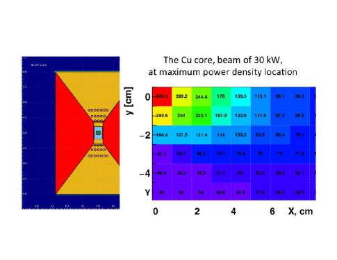
The transverse distribution of power is also very important to take into account because, for a high energy incident beam, it has a narrow peak. Simulation of the deposited power density and 2-dimensional heat flow analysis were performed to evaluate the maximum temperature in the absorber. Fig. 7 (left panel) shows the layout of materials in the model used for the temperature analysis. The calculation was performed for an 11 GeV, 30 kW beam and a radiator with 10% radiation length thickness. The resultant temperature was found to be below 400∘C, which is well in the acceptable range for copper. Fig. 7 (right panel) shows the temperature profile in the transverse plane at the longitudinal location of maximum power deposition. Cooling of the core will require about four gallons of water per minute at 110 psi pressure (at 30∘C temperature rise), which is easy to provide.
IV.4 Tungsten-powder Shield
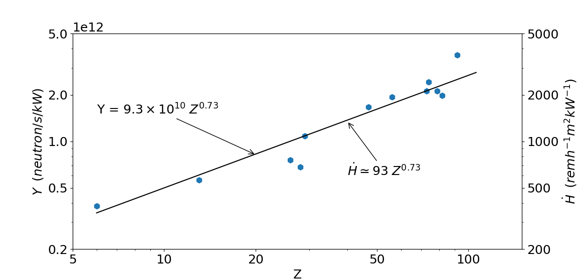
The amount of material needed for radiation shielding is primarily defined by the neutron attenuation length, which is 30 g/cm2 for neutrons with energy below 20 MeV and 125 g/cm2 for high energy neutrons. The neutron production rate by an electron beam in copper is per kW of beam power according to Ref. Swanson77 (see Fig. 8). At a distance of 16 meters from the unshielded source for a 30 kW beam, the neutron flux would be n/cm2/s, which would produce a radiation level of 110 rem/hr. The proposed conceptual design has a total shield mass of 850 g/cm2 and will result in a reduction in these radiation levels by a factor of around 1000.
The space inside the magnet between the poles and coils is filled by an inner copper absorber and an outer W-Cu(20%) insert, which provides a good balance between effective beam power absorption and radiation shielding. For the shield outside the magnet, the current design employs tungsten powder, whose high density (16.3 g/cm3) 111The density of tungsten is 19.25 g/cm3, but more commonly admixtures of tungsten and Cu/Ni, or in this case tungsten powder, are used with somewhat lower densities helps to reduce the total weight of the device. A thickness of 50 cm was used as a first iteration for the thickness of the outer shield of the CPS, but we have investigated the impact of varying this amount of outer shielding and adding borated plastic (as discussed later).
IV.5 Impact on Polarized Target
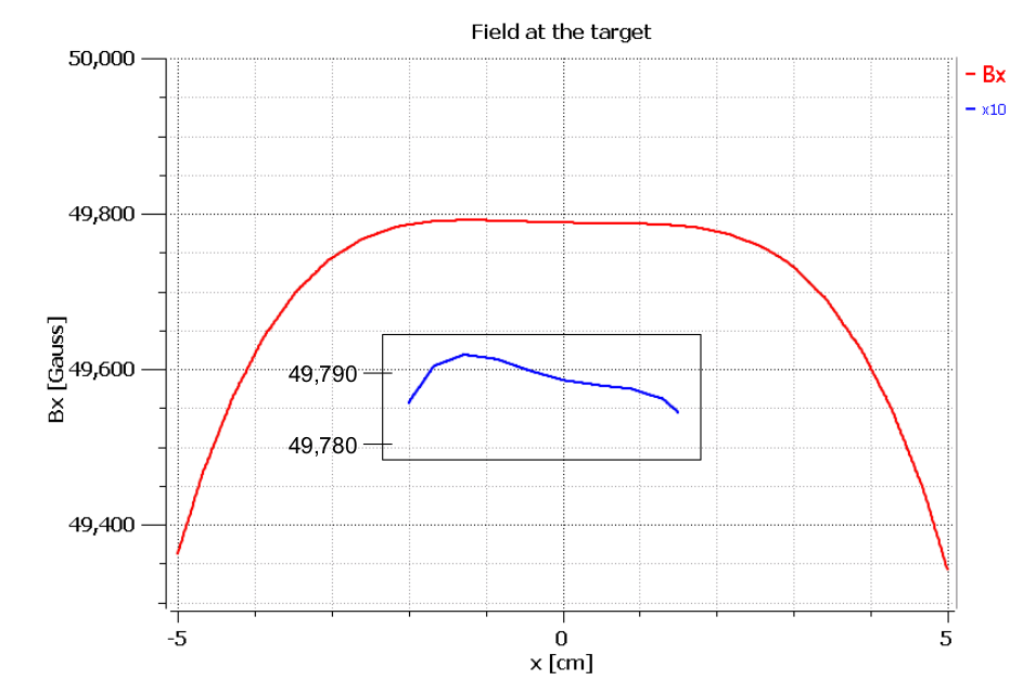
The most significant gain associated with deployment of the CPS is for experiments using dynamically polarized targets. However, such polarized targets operate with strong polarizing fields themselves. In addition, dynamically polarized target operation imposes strict requirements on the field quality at the target location, where fields and gradients need to be compensated at the 10-4 level. This necessitates studies of the mutual forces associated with the 2-3 Tesla CPS dipole magnet and the 5 Tesla polarized target solenoid, in terms of both the design of the support structures and the experimental operation.
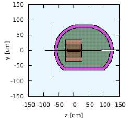
The fields associated with the combination of these two magnetic systems were calculated using the model shown in Fig. 9, with the following results obtained:
-
•
When the CPS is on but the polarized target magnet is off, the (total) field at the target location is 0.1 Gauss.
-
•
When the polarized target magnet is on and the CPS is off or removed, the field at the CPS location is about 130 Gauss.
-
•
When both the CPS and the polarized target magnet are ON, the field gradient at the polarized target center is about 2 Gauss/cm (Fig. 10).

These results show that, for the CPS the induced field is mainly due to the CPS magnet yoke becoming polarized by the target field. Whereas for the target, the field gradient at the target location is sufficiently low for routine dynamically polarized NH3 or ND3 operation, with a relative values of around .
V Radiation Requirements
As discussed previously, most of the proposed Jefferson Lab experiments with the CPS will utilize a dynamically nuclear polarized target. Electron beam currents for use with such targets are typically limited to 100 nA or less, to reduce both heat load and radiation damage effects. The equivalent heat load for a pure photon beam impinging on such a target corresponds to a photon flux originating from a 2.7 A electron current striking a 10 copper radiator. The radiation calculations presented in this section therefore assume a CPS able to absorb 30 kW of beam power (corresponding to a beam of 11 GeV electrons with a current of 2.7 A). In addition, the beam time assumed for a typical experiment is 1000 hours.
For such an experiment at Jefferson Lab, the following radiation requirements must be fulfilled:
-
•
The prompt dose rate in the experimental hall must be several rem/hr at a distance of 30 feet from the CPS.
-
•
The activation dose outside the CPS envelope at a distance of one foot must be several mrem/hr one hour after the end of a 1000 hour run.
-
•
The activation dose at the centre of the experimental target area, where operational maintenance tasks may be required at a distance of one foot from the scattering chamber must be several mrem/hr one hour after the end of a 1000 hour run.
The CPS conceptual design has been established with the aid of several extensive simulations. As validation of the simulation tools used, benchmark comparisons were made with GEANT3, GEANT4, FLUKA and DINREG. Geant4 ; Fluka 222Note that these codes calculate particle yields/s/cm2, which have to be converted into the effective dose rate (in rem/hr) using Fluence-to-Effective Dose conversion factors ICRP116 taking into account an energy-dependence factor.. After benchmark validation, a series of radiation calculations were performed in order to:
-
•
Determine the size and layout of the shielding around the magnet, and the choice of materials (copper, Cu-W alloy, concrete, borated plastic, etc.).
-
•
Determine the magnet field requirements in terms of peak field, gap size, and field length.
-
•
Determine the radiation levels on the magnet coils, and based on these results to identify radiation hardened materials that might be used in building the coils.
-
•
Determine the radiation levels on the polarized target electronics.
-
•
Determine the radiation levels directly adjacent to the CPS as well as at the experimental hall boundary.
VI Radiation Studies and Shielding Design
In this section we will describe studies performed for several different experimental configurations in order to identify the various sources of radiation and make direct comparisons of the calculated dose rates.
VI.1 Prompt Radiation Dose Rates
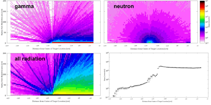
In order to provide a baseline the prompt radiation dose originating from a 2.7 A electron beam hitting a 10% copper radiator located at a distance of 2.15 m upstream of the centre of the experimental target was calculated. As the geometry of the target system and CPS are not included in this simulation, all prompt radiation originates from the interaction between the primary electron beam and the radiator. The prompt radiation dose is calculated by summing over all azimuthal angles in a radial range between 5 and 10 cm from the beam line.
Fig. 11 shows two-dimensional dose rates originating from photons only (top left), from neutrons only (top right), from all particles (bottom left), and the one-dimensional prompt radiation dose along the beam direction (bottom right). With the exception of the neutron contribution, most of the prompt radiation is created along the beam direction, as expected. The prompt radiation levels reach roughly 40 rem/hr, of which only around 200 mrem/hr is in the form of gamma radiation and 10 mrem/hr from neutrons. The remaining and clearly dominant contribution is from charged electron- and positron-induced showers.
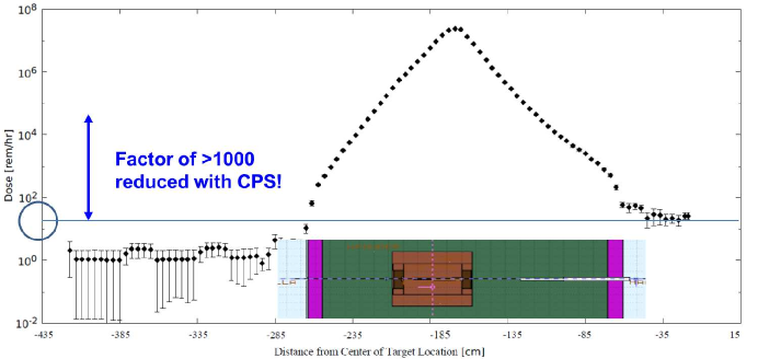
The second scenario considered is that of a 2.7 A electron beam incident on a 10% copper radiator as before, but with the radiator located within the CPS geometry. Fig. 12 illustrates the prompt radiation dose along the beam direction for this case (note that the y-axis scale on this figure is the same as in Fig. 11). One can clearly see that the prompt radiation levels within the CPS are much higher than before (around 300 times higher because the full power of the beam is now being deposited in the CPS). Crucially, however, the prompt radiation dose rate outside the CPS is only around 15 mrem/hr. Comparing this value for prompt dose rate to the one obtained above for the baseline scenario highlights the effect of the CPS shielding: there is a reduction by a factor of over 1000. This reduction is consistent with the factor estimated previously in section IV.4.
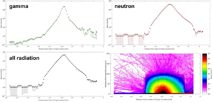
This is a very important result, which is further illustrated in Fig. 13. In contrast with the baseline scenario, there are now no contributions to the overall prompt dose rate in the experimental hall from photons, electrons and positrons as these are all contained within the CPS shielding – the neutron-only dose rate is nearly identical to the all-radiation rate. The bottom-right panel in Fig. 13 illustrates how well optimized the CPS shielding concept is for absorbing prompt radiation. Outside the CPS the prompt radiation dose rate on the surface (indicated by the outer black rectangular lines on the figure) is reduced to a maximum level of roughly 10 rem/hr. This is due to the fact that the development of showers generated by interactions of the primary beam is highly suppressed and the resultant secondary charged particles and photons are fully contained. This confirms that with a CPS the following requirement can be met: the prompt dose rate in the experimental hall several rem/hr at a distance of 30 feet from the device.
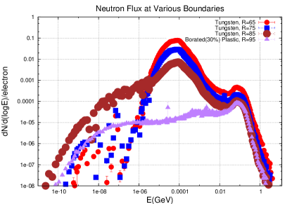
VI.2 Impact of Boron and Shielding Optimization
It is well known that the neutron flux through a surface can be drastically reduced by the addition of boron as a result of the very high capture cross section of 10B. This effect was simulated by calculating the neutron flux at the CPS boundary assuming various thicknesses of tungsten shielding (65, 75 and 85 cm), and then adding 10 cm of borated (30%) plastic. The result can be seen in Fig. 14, which shows the neutron flux as function of neutron energy. Increasing the tungsten thickness clearly reduces the neutron flux as expected, but a much more drastic reduction is seen when the 10 cm of borated plastic is added. Thus, the baseline conceptual shielding design of the CPS is assumed to be 85 cm thick tungsten surrounded by 10 cm of borated plastic.
The outer dimension of the tungsten-powder shielding as outlined for optimized shielding above is 1.7 m by 1.7 m by 1.95 m, or a volume of 5.63 m3. One needs to subtract from this total volume the inner box including the magnet, which amounts to 0.26 m3, leaving a net volume of 5.37 m3, or 88 tons of W-powder. There are various options to reduce the weight and therefore cost, if needed. One could reduce the overall size of the W-powder shielding by 5 cm on each side. This would result in a reduction of the shield weight to 73 tons, but would also lead to an increase of the radiation levels by about 50%. If one would remove an additional 10 cm only on the bottom side, there would be a further increase of a factor of two in radiation level in the direction of the floor, but a further reduction in shielding weight to 68 tons. Alternatively, one could round the W-powder corners, as illustrated in Fig. 15. This would complicate modular construction, but would allow for similar radiation levels as with the optimized design, while reducing rhe shielding weight to 66 tons.
VI.3 Dose Rates due to Activation
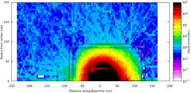
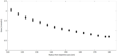
Dose rates due to the decay of activation products produced in the CPS during beam-on conditions have been calculated. Fig. 16(a) shows the calculated activation dose one hour after a 1000-hour experiment has been completed with the same conditions as before (2.7 A, 10% copper radiator, with shielded CPS). Fig. 16(b) shows the activation dose rate as a function of radial distance from the CPS. The activation dose outside the CPS is 2 mrem/hr at the surface and reduces radially outward. At a distance of one foot it is reduced to about 1.5 mrem/hr. This therefore demonstrates that the current design meets the requirement that the activation dose outside the device envelope at one foot distance is several mrem/hr after one hour following the end of a 1000 hour run.
Note that these estimates do not depend much on the assumed 1000-hour continuous running assumption, as similar dose rates are seen in a calculation for a 100-hour continuous run, reflecting the fact that much of the activation products are relatively short-lived. Furthermore, activation dose rates do not drop appreciably after one hour or even one day. On the other hand, after one month the activation dose rates at the CPS surface are reduced by up to a factor of ten. Inside the CPS the activation dose rate can be up to 1 krem/hr, which is why the CPS will be moved laterally to the side after an experiment rather than disassembled.
VI.4 Comparison with Dose Rates from the Target
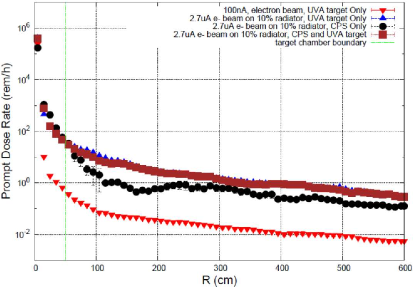
Fig. 17 shows the prompt dose at the target for different experimental configurations as a function of radial distance from the target centre. It is worth commenting on the results for three of these configurations: the 100 nA electron beam, the 2.7 A photon beam and the CPS with polarized target. At the boundary of the scattering chamber in the 100 nA electron beam configuration, the default operating mode for polarized beam experiments with dynamically nuclear polarized targets at Jefferson Lab to date, the prompt dose at the target is roughly 1 rem/hr. In the 2.7 A photon beam scenario it is roughly 30 rem/hr, which simply reflects the fact that even if a 2.7 A pure photon beam deposits the same heat load in a target as a 100 nA electron beam, the radiation rate is much higher. The CPS with polarized target scenario is identical to the pure photon beam case, further demonstrating that no additional radiation in the target area is created due to the presence of the CPS.
Similarly, Fig. 18 shows the activation dose rates for the same three configurations. One can see that the 2.7 A photon beam configuration has a much higher activation dose rate at the target than the 100 nA electron beam case. This again reflects what was seen in the previous figure for the prompt radiation dose rate, as there are many more photons coming from a 2.7 A electron beam on a 10% copper radiator than there are from a 100 nA electron beam on a roughly 3% dynamically nuclear polarized target. The effect of the CPS on the activation rate at the target is, as before, negligible.
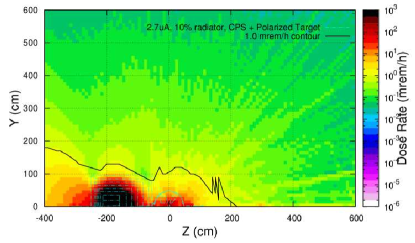
Fig. 19 shows a two-dimensional plot of the activation dose rate in the experimental hall one hour after a 1000 hour run with the CPS, a 2.7 A, 11 GeV beam on a 10% radiator and the polarized target system (at z = 0). The 1 mrem/hour contour is indicated, and demonstrates that with the current CPS baseline design, the activation dose at the target centre in the experimental target area, where operational maintenance tasks may be required, is dominated by the dose induced by a pure photon beam. At a distance of one foot from the scattering chamber it is several mrem/hr one hour after a 1000 hour run, as required.
VI.5 Material Considerations
The level of radiation of the CPS experiments is well below what is typical for many high-luminosity experiments at Jefferson Lab using regular cryogenic target systems and/or radiators. However, the radiation level on the polarized target coils, due to the interaction of the photon beam with the polarized target material, will be higher than in previous experiments (around 500 rem/hr as illustrated in Fig. 20). This is not expected to pose any significant issues. Furthermore, the radiation levels in the CPS magnet coils at a distance of 20 cm from the radiation source are around 1 Mrem/hr (see e.g. Fig. 13, bottom right). This relatively moderate level will allow the use of a modest-cost Kapton tape-based insulation of the coils Kapton .
VII Engineering and Safety Aspects
As stated earlier, cooling of the CPS core will require four gallons of water per minute at 110 psi pressure, which will result in a 30∘C rise in coolant temperature. Activation of this coolant water and beam dump is anticipated, meaning a closed-cycle cooling system will be needed. Activation inside the CPS will be confined to a very small volume and in the event of a leak, external contamination will be minimized. A leak pan under the device could easily be included to catch and confine any leakage up to and including a total loss of primary coolant. A modular pallet mounted design would be efficient and would include primary coolant pumps, DI resin beds, heat exchanger, surge tank, controls instrumentation and manifolds.
The combination of placing a high-power bremsstrahlung radiator, a magnet and a beam dump inside a shielded box imposes significant reliability and remote handling considerations. The primary engineering control involves making the design as robust as possible, including large safety margins and avoiding the need for disassembly for maintenance or any other reason. The CPS should be heavily instrumented for early detection of problems such as low coolant flow, leaks, low pressure, high temperature, and high conductivity. The two areas where conservative safety design is most needed are in the magnetic coil and dump cooling systems.
A low magnet coil current density design is envisioned, which is not expected to exceed 500 A/cm2. In order to allow easy access, individual coil pancake leads should be extended to an area outside of the magnet and shielding. There should be no electrical or coolant joints inside the shielding, and each separate sub-coil of the CPS magnet should have thermometers, thermal circuit breakers, voltage and coolant flow monitors to avoid any possibility that one of the separate current paths can overheat due to lack of sufficient coolant or a bad electrical contact. Extra insulation between sub-coils and between the coil and ground should be added to prevent ground faults. Lastly, a commercial power supply is assumed that will come with a wide array of internal interlock protections. The available interlocks and signals can be fed into the electron beam Fast Shutdown (FSD) system.
To protect equipment in the experimental hall from the beam striking the CPS shielding, a dual protection scheme using both a beam position monitoring system and direct instrumentation of the fast raster magnet is proposed. The beam diagnostics systems would monitor beam position and motion in close to real time and monitor coild voltage on the raster coils, which would provide ample early warning of raster problems. Both of these independent signals would be fed into the FSD system. Radiator temperature could be monitored to provide a third independent protection system, and if implemented, thermocouples mounted on the radiator should be robust against radiation damage and provide fast enough protection against radiator overheating.
VIII Summary
The Compact Photon Source (CPS) design features a magnet, a central copper absorber and hermetic shielding consisting of tungsten powder and borated plastic. The addition of the latter has a considerable impact on reducing the neutron flux escaping the CPS. The ultimate goal in this design process is that radiation from the source should be a few times less than from a photon beam interacting with the material of a polarized target. The equivalent heat load for a pure photon beam impinging such targets corresponds to a photon flux originating from a 2.7 A electron beam current striking a 10% copper radiator. Detailed simulations of the power density and heat flow analysis show that the maximum temperature in the absorber is below 400 degrees, which is well within the acceptable range of copper, and thus demonstrates that the CPS can absorb 30 kW in total, e.g. corresponding to an 11-GeV electron beam energy and a 2.7 A electron beam current.
The CPS also fulfills the requirements on operational dose rates at Jefferson Lab, which have been established with extensive and realistic simulations. The projected prompt dose rate at the site boundary is less than 1 rem/hr (to be compared with 2.4 rem/hr, which corresponds to a typical JLab experiment that does not require extra shielding). The activation dose outside the device envelope at one foot distance is less than several mrem/hr after one hour following the end of a 1000 hour run ( 3 months). The activation dose at the target centre in the experimental target area, where operational maintenance tasks may be required, is dominated by the dose induced by the pure photon beam. At a distance of one foot from the scattering chamber it is less than several mrem/hr one hour after the end of a 1000 hour run (i.e. the additional activation dose induced by absorption of the electron beam in the Compact Photon Source is negligible).
IX Acknowledgements
This work is supported in part by the National Science Foundation grants PHY-1306227, 1913257, and PHY-1714133, the U.S. Department of Energy, Office of Science, Office of Nuclear Physics award DE-FG02-96ER40950, and the United Kingdom’s Science and Technology Facilities Council (STFC) from Grant No. ST/P004458/1. We would like to thank Paul Brindza for helpful discussions and providing valuable input for the writing of this document. This material is based upon work supported by the U.S. Department of Energy, Office of Science, Office of Nuclear Physics under contract DE-AC05-06OR23177.
References
- (1) L.N. Hand, Phys. Rev. 129 (1963) 1834.
- (2) M. Kugler, Phys. Lett. 36B (1971) 44-46
- (3) K. Goeke, M.V. Polyakov and M. Vanderhaeghen, Prog. Part. Nucl. Phys. 47, 401 (2001)
- (4) S. Abrahamyan and B. Wojtsekhowski, report at NPS collaboration meeting, November 11, 2014, https://wiki.jlab.org/cuawiki/index.php/NPS_Collaboration_Meeting_(JLab,_11/19/14).
- (5) B. Wojtsekhowski and G. Niculescu, “Conceptual Design Report, A Compact Photon Source”, Supplementary material for the WACS proposal PR12-15-003 to the JLab PAC 43, June 2015; arXiv:1704.00816.
- (6) S. Ali et al., ”Workshop on High-Intensity Photon Sources (HIPS2017) Mini Proceedings”, arXiv:1704.00816
- (7) M.J. Amaryan, M. Bashkanov, S. Dobbs, J. Ritman, J.R. Stevens, and I.I. Strakovsky, and the KLF Collaboration, Jefferson Lab Experiment C12-19-001.
- (8) M. Diehl, Eur. Phys. J. C 25, 233 (2002); Phys. Rept. 388, 41 (2003).
- (9) M Burkardt, Nucl. Phys. A 711 (2002) 27; Int. J. Mod. Physics A 18 (2003) 173.
- (10) A.V. Belitsky and A.V. Radyushkin, Phys. Rept. 418, 1 (2005).
- (11) X. Ji, Phys. Rev. D 55, 7114 (1997); Phys. Rev. Lett.78, 610 (1997).
- (12) A.V. Radyushkin, Phys. Lett. B 385, 333 (1996); Phys. Lett. B 380, 417 (1996).
- (13) D. Mueller, D. Robaschik, B. Geyer, F.M. Dittes, J. Horejsi, Fortschr. Phys. 42, 101 (1994).
- (14) J.C. Collins, L. Frankfurt, M. Strikman, Phys. Rev. D 56, 2982 (1997).
- (15) J.C. Collins, A. Freund, Phys. Rev. D 59, 074009 (1999).
- (16) A.V. Radyushkin, Phys. Rev. D 58 114008 (1998)
- (17) M. Diehl, T. Feldmann, R. Jakob, P. Kroll, Eur. Phys. J. C 8 409 (1999)
- (18) P. Kroll, Eur. Phys. J. A53 no. 6, 130
- (19) P. Kroll, K. Passek-Kumericki, Phys. Rev. D97 no. 7, 074023
- (20) J. Dudek, R. Ent, R. Essig, K. Kumar, C. Meyer, R. McKeown, Z-E. Meziani, G.A. Miller, M. Pennington, D. Richards, L. Weinstein, G. Young, S. Brown, Eur. Phys. J. A48 (2012) 187.
- (21) APS Division of Nuclear Physics: 2014 Long-range plan Joint Town Meetings on QCD, available online: https://phys.cst.temple.edu/qcd/
- (22) DOE/NSF Nuclear Science Advisory Committee, ”Reaching for the Horizon - The 2015 Long Range Plan for Nuclear Science”, available online: http://science.energy.gov//̃media/np/nsac/pdf/2015LRP/2015_LRPNS_091815.pdf.
- (23) H.E. Montgomery, PoS INPC2016 (2017) 078, arXiv:1701.05183
- (24) W. J. Briscoe, M. Döring, H. Haberzettl, D. M. Manley, M. Naruki, I. I. Strakovsky, and E. S. Swanson, Eur. Phys. J. A51 (2015) 129.
- (25) M. Amaryan, E. Chudakov, C. Meyer, M. Pennington, J. Ritman, and I. Strakovsky, “Workshop on Physics with Neutral Kaon Beam at JLab (KL2016) Mini Proceedings”, arXiv:1604.02141.
- (26) E.R. Berger, M. Diehl, B. Pire, Eur. Phys. J. C 23 (2002) 675-689
- (27) I.V. Anikin et al., Acta Phys. Polon. B49 (2018) 741-784
- (28) S. V. Goloskokov and P. Kroll, Eur. Phys. J. C 65, 137 (2010) [arXiv:0906.0460 [hep-ph]].
- (29) S. V. Goloskokov and P. Kroll, Eur. Phys. J. A 47, 112 (2011) [arXiv:1106.4897 [hep-ph]].
- (30) G. R. Goldstein, J. O. Gonzales, Hernandez, S. Liuti, J. Phys. G 39 (2012) 115001.
-
(31)
D. Hamilton, D. Day, D. Keller, G. Niculescu, B. Wojtsekhowski, J. Zhang, and the Neutral Particle Spectrometer Collaboration, Jefferson Lab experiment E12-17-008.
-
(32)
M. Boer, D. Keller, V. Tadevosyan, and the Neutral Particle Spectrometer Collaboration, Jefferson Lab experiment C12-18-005.
- (33) E. Chudakov, D. Day, P. Degtiarenko, R. Ent, D.J. Hamilton, T. Horn, D. Keller, C. Keppel, G. Niculescu, P. Reid, I. Strakovsky, B. Wojtsekhowski, and J. Zhang, Compact Photon Source Conceptual Design, (2018). Available online: https://wiki.jlab.org/cuawiki/images/4/4f/CPS_document-rev9.pdf
- (34) R.L. Anderson et al., Physical Review Letters, 25, no. 17 (1970), 1218; R.L. Anderson et al., Physical Review D, 14, no. 3 (1976), 679; G.E. Fischer et al., Nucl. Inst. and Meth. 78 (1970), 25; Y.S. Tsai and V. Whitis, Physical Review, 149, no. 4 (1966), 1248.
- (35) N.R.S. Tait, Nuclear Instruments and Methods 67 (1969) 56; T.A. Armstrong et al., Physical Review D, Volume 5, Number 7, (1972); A. Jackson, Nuclear Instruments and Methods 129 (1975) 73.
- (36) G.R. Court et al., Nuclear Instruments and Methods 177 (1980) 281.
- (37) G.G. Crabb, W. Meyer, Ann. Rev. Nucl. Part. Sci. 47 (1997) 67.
- (38) B. Wojtsekhowski, D. Day, et al., PR05-101 (2005); P. Achenbach et al., MAMI-C.
- (39) T.D. Averett et al., Nucl. Inst. Meth. Phys. Research A 427 (1999) 440.
- (40) H. Zhu et al., Phys. Rev. Lett.87, 081801 (2001).
- (41) J. Pierce et al., Nucl. Inst. Meth. Phys. Research A 738 (2014) 54.
- (42) K.H. Tanaka et al., IEEE Trans. Appl. Supercond. 22 (2012) no. 3, 4100204.
- (43) V.V. Petrov et al., Tech. Phys. 61 (2016) no. 7, 1023.
- (44) W.P. Swanson, SLAC-PUB 2042 (1977); unpublished.
- (45) S. Agostinelli et al., Nucl. Inst. Meth. Phys. Research A 506 no. 3 (2003) 250; J. Allison et al., Nucl. Inst. Meth. Phys. Research A 835 0168-9002 (2016) 186
- (46) T.T. Boehlen et al., Nuclear Data Sheets 120, 211-214 (2014); A. Ferrari et al. ”FLUKA: a multi-particle transport code”, CERN-2005-10 (2005), INFN/TC_05/11, SLAC-R-773
- (47) ICRP, 2010. Conversion Coefficients for Radiological Protection Quantities for External Radiation Exposures. ICRP Publication 116, Ann. ICRP 40(2–5).
- (48) V.V. Petrov, Yu.A. Pupkov, a report “BINP TESTING OF RADIATION RESISTANCE OF THE MATERIALS USED FOR PRODUCTION OF ACCELERATOR MAGNETIC SYSTEMS”, Novosibirsk, 2011
- (49) P.K. Kloeppel, “Design for 25-kW beam dumps at 100 MeV and 500 MeV”, CEBAF-TN-90-205; M. Wiseman, C.K. Sinclair, R. Whitney, M. Zarecky, “High Power Electron Beam Dumps at CEBAF”.