Zero field splitting of heavy-hole states in quantum dots
Abstract
Using inelastic cotunneling spectroscopy we observe a zero field splitting within the spin triplet manifold of Ge hut wire quantum dots. The states with spin in the confinement direction are energetically favored by up to eV compared to the spin 0 triplet state because of the strong spin orbit coupling. The reported effect should be observable in a broad class of strongly confined hole quantum-dot systems and needs to be considered when operating hole spin qubits.
pacs:
73.23.Hk; 71.70.Ej; 73.63.KvHole states in semiconductor quantum dots have gained increasing interest in the past few years as promising candidates for spin qubits due to their strong spin orbit coupling (SOC) Winkler (2003); Kloeffel et al. (2011); Hong et al. (2018). Thanks to the SOC one now has a full-fledged electrical control of the hole spins Maurand et al. (2016); Watzinger et al. (2018); Hendrickx et al. (2019); Crippa et al. (2019), either via the electric-dipole spin resonance Golovach et al. (2006), g-tensor modulation Kato et al. (2003), or both Crippa et al. (2018). Further, Rabi frequencies exceed 100MHz Watzinger et al. (2018); Hendrickx et al. (2019) and reflectometry measurements reveal spin relaxation times of s at Vukušić et al. (2018), which underlies the big potential of hole spins as viable qubits.
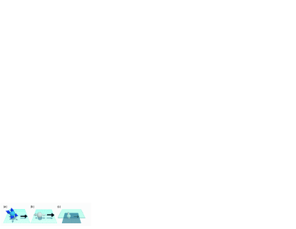
Despite the fact that a hole is simply a missing electron, their spins behave strikingly different than their electron counterparts Kloeffel et al. (2018). While the electron spin does not correlate with the direction of motion in typical semiconductors given their weak SOC [Fig. 1(a)]; the hole pseudospin points in the same direction as the momentum [Fig. 1(b)] already for bulk materials. This can be described by the Luttinger-Kohn Hamiltonian Luttinger and Kohn (1955); Luttinger (1956) for holes near the point of the valence band, imposing a coupling between the momentum and the hole pseudospin.
By introducing a strong confinement potential creating a quantum well, the heavy-hole (HH) light-hole (LH) degeneracy is lifted and the pseudospin changes its direction. For the HH states, which become energetically favorable, the pseudospin now points perpendicular to the momentum, i.e., in the direction of strong confinement [Fig. 1(c)] Kloeffel et al. (2018). This implies that HHs confined in quasi two dimensional quantum dots (QDs), i.e., artificial atoms with strong confinement in one dimension, show spin anisotropy and could thus manifest similar effects as atoms show in the presence of a magnetocrystalline anisotropy, i.e., a magnetic anisotropy leading to a zero field splitting (ZFS). However, to the best of our knowledge hitherto no ZFS has been observed for quantum dots.
For adatoms, on the other hand, ZFS studies have been at the focus of intense research as the magnetic anisotropy provides directionality and stability to the spin, which is the key for realizing nanoscale magnets. Scanning tunneling microscopy measurements have been used to reveal the magnetic anisotropy for several adatoms on surfaces and to understand how the local environment can influence it Rau et al. (2014); Jacobson et al. (2015); Miyamachi et al. (2013); Gambardella et al. (2003); Hirjibehedin et al. (2007). ZFS as high as , originating from the atomic spin orbit interaction, have been reported Rau et al. (2014).
Here, we use inelastic co-tunneling (CT) to extract information about confined HH states. A hole-hole interaction strength of eV, similar to that of GasAs is reported. We have furthermore investigated the spin anisotropy of HH states confined in quasi two dimensional QDs. We measure a ZFS of up to eV for the excited triplet states confined in a QD with an even hole occupation. The evolution of the triplet states both for perpendicular and parallel magnetic fields is in very good agreement with the anisotropic Hamiltonian for the spin-triplet.
The QDs used for this study are fabricated in Ge hut wires (HWs) grown by molecular beam epitaxy Gao et al. (2020); Zhang et al. (2012). These HWs are site-controlled as they are grown on Si wafers with predifined trenches [Fig. 2(a)]. The detailed description of the growth conditions can be found in Ref. Gao et al. (2020). They have a height of about 3.8nm and a width of approximately 38nm. Due to the strong confinement and compressive strain, the degeneracy between the HH and LH is lifted, leading to confined HH states Katsaros et al. (2011); Watzinger et al. (2016). The HWs are contacted by two -nm-thick Pt electrodes, acting as source and drain, with a -nm spacing between them. The gate electrode consists of -nm Ti plus -nm and is separated from the source and drain contacts by hafnium oxide, deposited in cycles of atomic layer deposition [Fig. 2(b)]. Two nominally identical devices from the fabricational point of view have been investigated in this study.
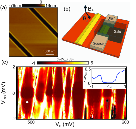
At low temperatures, transport through QDs is dominated by Coulomb blockade (CB), which leads to single electron transport. The stability diagram of a QD device with the characteristic Coulomb diamonds can be seen in Fig. 2(c). However, due to second-order elastic CT processes the conductance within the coulomb diamonds does not drop to zero Kogan et al. (2004); De Franceschi et al. (2001). At zero magnetic field, once the energy due to the bias voltage across the QD exceeds the orbital level separation, , the inelastic CT process leaves the QD in the excited orbital state ( denotes the elementary charge). The onset of inelastic CT is observed as a step in the differential conductance, , at De Franceschi et al. (2001); Kogan et al. (2004); Katsaros et al. (2010), indicated by black arrows in Fig. 2(c).
Inelastic CT is an excellent tool for magnetotransport spectroscopy measurements as the step width is not lifetime limited but depends only on the effective temperature De Franceschi et al. (2001). We first use it to extract information related to the strength of hole-hole interactions within a QD. When a QD confines an odd number of holes, the ground state is a (doubly degenerate) spin-doublet. On the other hand, with an even number of holes the ground state of the QD is a singlet state (assuming that the exchange coupling is weaker than the level splitting). Here, the two holes occupy the same (lowest in energy) orbital state with their pseudospins being antiparallel. The first excited states are the triplet states for which one hole occupies a higher orbital. This costs a higher energy for the orbital occupation but also gains some Coulomb repulsion energy compared to the singlet state Hanson et al. (2007); Kouwenhoven et al. (2001). By comparing the difference between the singlet-triplet energy and the orbital level separation , one can thus obtain useful information about the strength of hole-hole interactions.

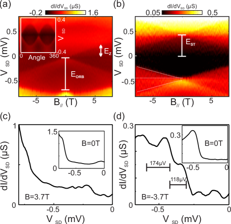
In order to conclude about the even/odd occupancy of the QD we investigate the evolution of the CT steps. For an odd number of holes, a magnetic field lifts the spin degeneracy of the doublet state by the Zeeman energy , where and are the hole g-factor and Bohr magneton, respectively. Once the energy due to the bias voltage across the QD exceeds the Zeeman energy, , the inelastic CT processes can flip the QD spin, leaving the QD in the excited spin state. This is visible as a step in Fig. 3(a). For zero magnetic field the observed feature corresponds to the first orbital excited state from which an orbital level separation of eV can be extracted. For an even number of holes, on the other hand, the magnetic field should split the three triplet states, and three inelastic cotunneling steps should be observed (note that the other state involved, the ground state singlet, does not split in a magnetic field). Indeed this behavior can be observed in Figs. 3(b) and (d). In this case the feature at zero field corresponds to the energy of the triplet states. The measured singlet triplet energy separation is eV. The difference eV corresponds to the Coulomb interaction energy and is similar to what has been reported for GaAs QDs Hanson et al. (2007).
By inspecting carefully the behavior of the triplet states in Fig. 3(b), it can be seen that the triplets are not equally spaced (Fig. 3(d)); it actually seems that the three triplet states (marked by three dashed lines) are not degenerate at . Ge is known to have a very strong atomistic (valence band) SOC which leads to the HH spin poiting in the perpendicular direction of Fig. 1 (c). We can envisage the triplet state as being made up of two such HH spins. This or, even more general, any triplet with an anisotropy in the - direction of Fig. 2(b) can be described by the following Hamiltonian for the triplet spin (see e.g. Mis ; Bru ):
| (1) |
Here, and are the projections in the - and -direction of Fig. 2(b) and the terms of the Hamiltonian are from right to left: The magnetic anisotropy term which makes it preferably by an energy to align the triplet spin-1 in the -direction with strongest confinement. Its origin will be discussed in the next paragraph. The next two terms describe the Zeeman term with the magnetic field in the two directions, and , coupling through different (anisotropic) and -factors. Finally, we also include the exchange term which differentiates singlet and triplet, but is not relevant in the following as we concentrate on the magnetic field dependence of the triplet states ( fixed) only.
From the effective Hamiltonian (1) for the triplet states we cannot distinguish the origin of the magnetic anisotropy. It might be due to (i) shape anisotropy caused by dipole interactions Bru , (ii) single ion (single quantum dot) anisotropy caused by SOC-induced transitions to excited (virtual) states Mis ; Bru or (iii) a SOC-induced anisotropic exchange Burkard and Loss (2002); Shim et al. (2011).
The last microscopic origin is certainly most natural if we think of the triplet spin- state as being made up out of two HH spin states, which we can describe as two coupled pseudospin-, and . Given that these pseudospins actually describe HH spin states (or the strong SOC coupling from a general perspective) the coupling of these pseudospins has to be anisotropic, i.e., . This reduces to Eq. (1) with and in the triplet subspace, up to a constant.
The eigenstates of Hamiltonian (1) can be easily calculated and are shown in Fig. 4 for a magnetic field applied once in the - and once in the -direction. For the two states with have a by smaller energy than the third triplet state with . Hence, the lowest triplet state is doubly degenerate and the remaining one singly degenerate in Fig. 4. Applying now a magnetic field in the anisotropy direction Zeeman-splits the doublet and leaves the singly degenerate state untouched (Fig. 4 (a)), with .
The situation with the magnetic field orthogonal to the anisotropy direction is somewhat more complicated. Here, for small , the eigenstates are still predominately with only a small, perturbative readmixture as the magnetic field tries to align the spins in the -direction. This linear readmixture of the eigenstates, leads to a quadratic change of the energy eigenvalues in Fig. 4 (b) for . For large , the usual Zeeman splitting of the triplet states into is recovered as the HH pseudo spins now reorient along . This is in very good agreement with the data shown in Fig. 3(b), even though we have not adjusted the parameters but extracted these experimentally from Fig. 3(b) and similar line traces at other ’s. An even better agreement is obtained when freely adjusting and (not shown).
These considerations clearly show that there is a ZFS and that the magnetic field dependence shows a quite different behavior for and . If we have an odd number of electrons, the doublet could also be described with Hamiltonian (1). But in this case, both states have the same anisotropy energy. Hence there is a Zeeman splitting but no ZFS as observed in Fig. 3(a).
In order to further elucidate this behavior of the triplet state, we study in Figures 4 (c), (d) the dependence on a magnetic field . Using a second derivative to sharpen the features, it can be seen even more clearly that the HH triplet states are not degenerate at . Even more, the magnetic field evolution perfectly fits with that of Fig. 4(a), which is also indicated as dashed (white) lines. Figures 4 (e,f) show the same split degeneracy also for a second device. In this case orbital effects also lead to a slight bending of the states for and the ZFS is extracted to be eV. Except for this extra bending Fig. 4 (e) resembles Fig. 4(a) and Fig. 4 (f) resembles Fig. 4(b) for the two different magnetic field directions. From the observed splitting it is obvious that the ZFS needs to be taken into account when considering the energy band diagram of double QDs, for which it has been assumed so far, that triplet HH states are all degenerate at .
In conclusion, we have demonstrated the ZFS for heavy hole states confined in a two dimensional quantum dot. Specifically, the triplet states are split into a double and a single degenerate level. This is not only of fundamental interest but also needs to be taken into account, for better or for worse, when operating heavy hole qubits Watzinger et al. (2018); Hendrickx et al. (2019). It can be exploited for rotating and preparing a well defined quantum state using Rabi oscillations at the ZFS (microwave) frequency, similar as for nitrogen vacancy centers in diamond Fuchs et al. (2009); Jelezko and Wrachtrup (2006). A small magnetic field can further help addressing the spin states individually. If we consider the anisotropic exchange as the origin of the ZFS, it can be employed for qubit operations Shim et al. (2011) but may also be tuned (more) isotropic using proper pulse shaping Bonesteel et al. (2001); Burkard and Loss (2002).
We acknowledge G. Burkard, C. Kloeffel, D. Loss, P. Rabl and M. Rančić for helpful discussions. We further acknowledge T. Adletzberger, J. Aguilera, T. Asenov, S. Bagiante, T. Menner, L. Shafeek, P. Taus, P. Traunmüller and D. Waldhäusl for their invaluable assistance. This research was supported by the Scientific Service Units of IST Austria through resources provided by the MIBA Machine Shop and the nanofabrication facility, by the FWF-P 32235 project, by the National Key R&D Program of China (Grants No. 2016YFA0301701, 2016YFA0300600) and the European Union’s Horizon 2020 research and innovation program under Grant Agreement #862046.
References
- Winkler (2003) R. Winkler, ed., Spin-Orbit Coupling Effects in Two-Dimensional Electron and Hole Systems (Springer New York, 2003).
- Kloeffel et al. (2011) C. Kloeffel, M. Trif, and D. Loss, Phys. Rev. B 84, 195314 (2011).
- Hong et al. (2018) L. Hong, E. Marcellina, A. Hamilton, and D. Culcer, Phys. Rev. Lett. 121, 087701 (2018).
- Maurand et al. (2016) R. Maurand, X. Jehl, D. Kotekar-Patil, A. Corna, H. Bohuslavskyi, R. Laviéville, L. Hutin, S. Barraud, M. Vinet, M. Sanquer, and S. De Franceschi, Nature Com. 7, 13575 (2016).
- Watzinger et al. (2018) H. Watzinger, J. Kukučka, L. Vukušić, F. Gao, T. Wang, F. Schäffler, J. J. Zhang, and G. Katsaros, Nature Com. 9, 3902 (2018).
- Hendrickx et al. (2019) N. W. Hendrickx, D. P. Franke, A. Sammak, G. Scappucci, and M. Veldhorst, (2019), arXiv:1904.11443 (2019).
- Crippa et al. (2019) A. Crippa, R. Ezzouch, A. Aprá, A. Amisse, R. Laviéville, L. Hutin, B. Bertrand, M. Vinet, M. Urdampilleta, T. Meunier, M. Sanquer, X. Jehl, R. Maurand, and S. De Franceschi, Nature Com. 10, 2776 (2019).
- Golovach et al. (2006) V. N. Golovach, M. Borhani, and D. Loss, Phys. Rev. B 74, 165319 (2006).
- Kato et al. (2003) Y. Kato, R. C. Myers, D. C. Driscoll, A. C. Gossard, J. Levy, and D. D. Awschalom, Science 299, 1201 (2003).
- Crippa et al. (2018) A. Crippa, R. Maurand, L. Bourdet, D. Kotekar-Patil, A. Amisse, X. Jehl, M. Sanquer, R. Laviéville, H. Bohuslavskyi, L. Hutin, S. Barraud, M. Vinet, Y.-M. Niquet, and S. De Franceschi, Phys. Rev. Lett. 120, 137702 (2018).
- Vukušić et al. (2018) L. Vukušić, J. Kukučka, H. Watzinger, J. M. Milem, F. Schäffler, and G. Katsaros, Nano letters 18, 7141 (2018).
- Kloeffel et al. (2018) C. Kloeffel, M. J. Rančić, and D. Loss, Phys. Rev. B 97, 235422 (2018).
- Luttinger and Kohn (1955) J. M. Luttinger and W. Kohn, Phys. Rev. 97, 869 (1955).
- Luttinger (1956) J. M. Luttinger, Phys. Rev. 102, 1030 (1956).
- Rau et al. (2014) I. G. Rau, S. Baumann, S. Rusponi, F. Donati, S. Stepanow, L. Gragnaniello, J. Dreiser, C. Piamonteze, F. Nolting, S. Gangopadhyay, O. R. Albertini, R. M. Macfarlane, C. P. Lutz, B. A. Jones, P. Gambardella, A. J. Heinrich, and H. Brune, Science 988, 344 (2014).
- Jacobson et al. (2015) P. Jacobson, T. Herden, M. Muenks, G. Laskin, O. Brovko, V. Stepanyuk, M. Ternes, and K. Kern, Nature Com. 6, 8536 (2015).
- Miyamachi et al. (2013) T. Miyamachi, T. Schuh, T. Märkl, C. Bresch, T. Balashov, A. Stöhr, C. Karlewski, S. André, M. Marthaler, M. Hoffmann, M. Geilhufe, S. Ostanin, W. Hergert, I. Mertig, G. Sch’́on, A. Ernst, and W. Wulfhekel, Nature 503, 242 (2013).
- Gambardella et al. (2003) P. Gambardella, S. Rusponi, M. Veronese, S. S. Dhesi, C. Grazioli, A. Dallmeyer, I. Cabria, R. Zeller, P. H. Dederichs, K. Kern, C. Carbone, and H. Brune, Science 300, 1130 (2003).
- Hirjibehedin et al. (2007) C. F. Hirjibehedin, C. Y. Lin, A. F. Otte, M. Ternes, C. P. Lutz, B. A. Jones, and A. J. Heinrich, Science 317, 1199 (2007).
- Gao et al. (2020) F. Gao, J.-H. Wang, H. Watzinger, H. Hu, M. J. Rančić, J.-Y. Zhang, T. Wang, Y. Yao, G.-L. Wang, J. Kukučka, L. Vukušić, C. Kloeffel, D. Loss, F. Liu, G. Katsaros, and J.-J. Zhang, Advanced Materials n/a, 1906523 (2020).
- Zhang et al. (2012) J. J. Zhang, G. Katsaros, F. Montalenti, D. Scopece, R. O. Rezaev, C. Mickel, B. Rellinghaus, L. Miglio, S. De Franceschi, A. Rastelli, and O. G. Schmidt, Phys. Rev. Lett. 109, 085502 (2012).
- Katsaros et al. (2011) G. Katsaros, V. N. Golovach, P. Spathis, N. Ares, M. Stoffel, F. Fournel, O. G. Schmidt, L. I. Glazman, and S. De Franceschi, Phys. Rev. Lett. 107, 246601 (2011).
- Watzinger et al. (2016) H. Watzinger, C. Kloeffel, L. Vukušić, M. D. Rossell, V. Sessi, J. Kukučka, R. Kirchschlager, E. Lausecker, A. Truhlar, M. Glaser, A. Rastelli, A. Fuhrer, D. Loss, and G. Katsaros, Nano letters 16, 6879 (2016).
- Kogan et al. (2004) A. Kogan, S. Amasha, D. Goldhaber-Gordon, G. Granger, M. A. Kastner, and H. Shtrikman, Phys. Rev. Lett. 93, 166602 (2004).
- De Franceschi et al. (2001) S. De Franceschi, S. Sasaki, J. M. Elzerman, W. G. van der Wiel, S. Tarucha, and L. P. Kouwenhoven, Phys. Rev. Lett. 86, 878 (2001).
- Katsaros et al. (2010) G. Katsaros, P. Spathis, M. Stoffel, F. Fournel, M. Mongillo, V. Bouchiat, F. Lefloch, A. Rastelli, O. G. Schmidt, and S. De Franceschi, Nature Nanotechnology 5, 458 (2010).
- Nenashev et al. (2003) A. Nenashev, A. Dvurechenskii, and A. Zinovieva, Phys. Rev. B 67, 205301 (2003).
- Hanson et al. (2007) R. Hanson, L. P. Kouwenhoven, J. R. Petta, S. Tarucha, and L. M. K. Vandersypen, Rev. Mod. Phys. 79, 1217 (2007).
- Kouwenhoven et al. (2001) L. P. Kouwenhoven, D. G. Austing, and S. Tarucha, Rep. Prog. Phys. 64, 701 (2001).
- (30) See e.g. M. Misiorny, M. Hell, and M. R. Wegewijs Nature Physics 9, 801 (2013) .
- (31) For a pedagogical discussion of various magnetic anisotropy terms, see P. Bruno, Physical Origins and Theoretical Models of Magnetic Anisotropy, in 24. IFF-Ferienkurs Forschungszentrum Jülich (Forschungszentrum Jülich, Jülich, 1993); ISBN 3893361103 .
- Burkard and Loss (2002) G. Burkard and D. Loss, Phys. Rev. Lett. 88, 047903 (2002).
- Shim et al. (2011) Y.-P. Shim, S. Oh, X. Hu, and M. Friesen, Phys. Rev. Lett. 106, 180503 (2011).
- Fuchs et al. (2009) G. D. Fuchs, V. V. Dobrovitski, D. M. Toyli, F. J. Heremans, and D. D. Awschalom, Science 326, 1520 (2009), https://science.sciencemag.org/content/326/5959/1520.full.pdf .
- Jelezko and Wrachtrup (2006) F. Jelezko and J. Wrachtrup, physica status solidi (a) 203, 3207 (2006).
- Bonesteel et al. (2001) N. E. Bonesteel, D. Stepanenko, and D. P. DiVincenzo, Phys. Rev. Lett. 87, 207901 (2001).