-
September 2019
Self Sustained Thermally Induced Gas-Damped Oscillations of Bimetal Cantilevers with Application to the Design of a New Pyroelectric Micro Energy Harvester
Abstract
Low efficiency is the main drawback of many MEMS thermal energy harvesters. Recently, energy harvesting micro-devices that operate using the pyroelectric effect gained attention due to their potential superior performance. Operation of these devices is based on the cyclic motion of a pyroelectric capacitor that operates between a high temperature and a low temperature reservoirs. In this paper, we investigate the dynamics of oscillations of a pyroelectric capacitor self sustained by thermally actuated bimetal micro-cantilevers, a topic which is so far underinvestigated. In addition to highlighting key thermodynamic aspects of the operation, we explore conditions for self-sustained oscillations and discuss the viability of operation at the mechanical resonance frequency. The analysis is presented for a new design inspired by the device proposed in Refs.[1, 2], where in contrast, our proposed design boasts the following features: The pyroelectric capacitor remains parallel to the heat reservoirs, by virtue of its symmetric support by two bimetallic cantilever beams; In addition, the cyclic operation of the device does not require physical contact, thus lowering the risk of mechanical failure; To adjust the damping force imparted by the surrounding gas, the thermal reservoirs are equipped with trenches. To study the dynamic operation of the device, we developed a physically based reduced order, yet accurate, model that accounts for the heat transfer between and within the different components, and for the various forces including the gas damping force. The model is embedded within an optimization algorithm to produce optimal designs over the range of temperature difference between the two reservoirs. The corresponding range of harvested power density is 0.4-0.65 .
Keywords: Energy Harvesting, Pyroelectric, MEMS, Self sustained, Thermally Induced, bimetal micro-cantilever
1 Introduction
It has been reported that a substantial amount of the consumed energy in the USA is wasted as heat [3, 4]. Therefore, considerable research effort has been directed towards harvesting energy from these waste sources. This in turn would offer a long lasting green power and maintenance free devices. Most of the research in this domain has been focused on utilizing thermoelectric materials which rely on the spatial gradient of temperature (). This temperature gradient can be easily realized without the need for moving parts, which is a desirable design feature. Thermoelectric devices are, however, not suited for applications where the temperature is below 100 [4]. Moreover, extensive research on thermoelectric generators showed that their efficiency could not exceed 1-5%[1]. In contrast, pyroelectric devices depend on the time variation of temperature () for power conversion, which is realized by cyclic motion of the pyroelectric capacitor operating between a high and a low temperature reservoirs.
It is worth noting that the efficiency of pyroelectric devices is greatly affected by their operation frequency. That is the closer the frequency to the mechanical resonance frequency, the higher the device efficiency. The operation frequency in bulk devices is expected to be in the order of 1-5 Hz, which is orders of magnitude below the resonance frequency. This is due to limitations in the diffusion-based heat transfer processes and/or others imposed by the actuation mechanism. In order to increase the operation frequency, heat exchange between the pyroelectric capacitor and the thermal reservoirs should be sufficiently fast. This can be accomplished by reducing the gap separating the capacitor and the heat source (sink) to the sub-micron length scale [5], causing the much faster radiative heat transfer to be the dominant mode of heat transfer. It has also been proposed to use thin films as a simple mean to improve the heat transfer rate [6]. Equally important for fast operation of the device is the speed of the actuation mechanism. Self sustained cyclic motion of the pyroelectric plate using thermally actuated bimetal cantilevers is proposed in Refs.[2, 1]. In this case, heat transfer by conduction along the bimetal cantilevers is a speed limiting mechanism. Alternatively, actuation through piezoelectric nano-pillars is proposed in Ref. [6]. Although fast, this actuation method requires electric input work for actuation which, for acceptable values of the overall efficiency (or net generated work), yields small displacements of the pyroelectric capacitor. This, in turn, keeps the distance between the plate and the heat source/sink relatively large, which limits the heat exchange rate. This may explain why the operation frequency does not exceed 10 Hz which is well below the natural frequency of the device [6].
Self sustained oscillations (SSO) of piezo-electrically actuated micro-cantilevers have been widely used in many MEMS devices such as photo-detectors [7], atomic force microscopy [7] and sensors [8, 9, 10]. In these systems, the oscillator is usually made from a single metallic or semiconducting material and their vibratory behaviors in different environments (air, liquid and even vacuum) are well understood [11]. However, the literature is lacking when it comes to the analysis of gas-damped SSO of bimetal cantilevers actuated by cyclic temperature variation, such as those encountered in pyroelectric microdevices. It is therefore of paramount importance for reliable design of such systems to investigate their dynamic behavior. It is well documented that at nano-microscale, the performance of microdevices with vibrating components is strongly affected by the viscous damping due to their interaction with the surrounding fluid. In parallel plate MEMS capacitors, for example, the distance between the capacitor plates is usually minimized for improved efficiency [12]. This potentially may result in non-continuum fluid-solid interaction due to the formation of squeezed film damping.
In this paper, we propose a new pyroelectric micro energy harvester. We use the proposed device to investigate the dynamics of thermally induced self sustained oscillations of bimetal micro-cantilevers using a physically-based reduced order, yet accurate, model that we developed for this purpose. The model accounts for the heat transfer between and within the different components, and for the various forces including the damping force induced by the squeeze gas film. We then employ this model within an optimization loop to arrive at nearly optimal dimensions of the proposed design over a range of the temperature difference between the high and low temperature reservoirs. The proposed design is inspired by the device proposed in Refs.[1, 2], which consists of a proof mass supported by a bimaterial canitlever that serves at the same time as the pyroelectric capacitor. The proof mass which oscillates between the high and low temperature reservoirs serves as a thermal capacitor that stores heat when it contacts the high temperature reservoir (HTR) and loses heat when it contacts the low temperature reservoir (LTR). The oscillation, which generates an electrical current in the pyroelectric capacitor, is actuated by the downward and upward bending of the bimorph cantilever as a result of heat transfer from the proof mass to the bimaterial cantilever and vice versa. Our proposed device was designed, in part, to overcome the following limitations in the device proposed in Refs.[1, 2]. The asymmetrical shape of the device requires tilting of the proof mass so that contact with the reservoir walls occurs over a small area. This design limits the rate of heat transfer between the proof mass and the thermal reservoirs due to the resulting high contact thermal resistance. In addition, direct contact over a large number of operation cycles may lead to failure[13, 14, 15]. Moreover, heat gained by the proof mass upon contact with the HTR flows in the pyroelectric capacitor along its length. The resulting pyroelectric effect, which depends on the spatial distribution of the temperature variation with time decreases along the bimetal cantilever length away from the capacitor.
This paper is organized as follows. The proposed design is presented in Section 2. In Section 3, we highlight key thermodynamic aspects of the operation. The reduced order model we developed to design the device and investigate its dynamic operation is presented in Section 4. Dynamic operation of the device is investigated in Section 5. In Section 6, we outline key design considerations, discuss conditions for sustained oscillations, and present a simple design procedure for device operation at the mechanical resonance frequency. Assessment of the validity and accuracy of the model is conducted in Section 7. Optimized designs and trends characterizing key performance indicators including the energy output are presented in Section 8.
2 The Proposed Device
The proposed device, which has a symmetric design, is presented in Fig. 1. The pyroelectric capacitor, shaped as a rectangular plate of large area in the plane, is connected to the bimetal cantilevers by means of four tethers. Since heat exchange between the pyroelectric capacitor and the heat reservoirs takes place directly over a large area (in the plane), the time it takes to thermally charge and discharge the capacitor is very small. This, in addition to designing the tethers to have sufficiently large thermal resistance, guarantees a nearly spatially uniform temperature distribution in the pyroelectric capacitor at all times. The tethers are also designed to have low torsional and bending stiffness which allows them to rotate about their axis (along the direction) and bend in the -direction with negligible effect on the pyroelectric plate so that it remains rigid and horizontal during the actuation.
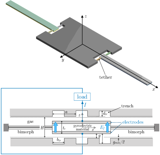
Each bimetal cantilever is composed of two metals of different heat expansion coefficients which force it to bend with temperature variation. When the pyroelectric capacitor gets in contact with the HTR, its temperature rises (approaching that of the HTR) and heat diffuses toward the bimetal cantilever through the tethers. Choosing the upper layer metal to have have the higher heat expansion coefficient forces the cantilever to bend downward and push the pyroelectric plate toward the the LTR. Upon contact with the LTR, the pyroelectric plate temperature decreases approaching that of the LTR. As the cantilevers cool down, they bend upward. The cycle starts again when the plate reaches the HTR.
In addition, the proposed design of Fig. 1 does not require direct (solid-solid) contact between the capacitor and the reservoirs. We assume that the plate stops when it gets within a distance of from either reservoir. Although this results in reduction in the output power and efficiency due to the additional thermal resistance of the gas film (of thickness ), this sacrifice alleviates all the challenges associated with physical contact, and as such increases the life of the device. Although we do not discuss the stopping mechanism in this work, we point out that it is possible, in theory, to design the device such that it oscillates in an autonomous fashion without hitting either reservoir and without the need for an additional stopping mechanism.
3 Thermodynamics Model
A pyroelectric material is a special type of piezoelectric materials[16] that undergoes spontaneous polarization when its temperature varies in time. In engineering applications, the pyroelectric material is typically oriented along the principal crystallographic direction[17, 18]. In the presence of an external electric field, , applied along the same direction, the pyroelectric effect is quantified in terms of the generalized pyroelectric coefficient, , measuring the increase in surface the charge density111The magnitude of the electric displacement at the surface of a conductor., , per unit increase in the temperature:
| (1) |
where
| (2) |
is the spontaneous polarization, is the temperature, is the Curie temperature, and is the electrical permittivity of the pyroelectric.
The current flowing to the external circuit, shown in Fig. 1, is then expressed as:
| (3) |
where is the area of the electrode plates. It should be noted that the effect of permittivity variation with temperature can be comparable to the spontaneous pyroelectric effect and can also be seen above the Curie point [17].
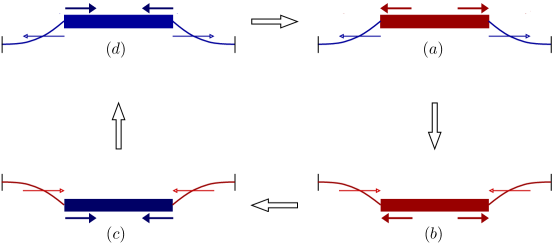
As the plate, shown in Fig. 1, travels back and forth between the HTR and the LTR, the pyroelectric material (sandwiched between the capacitor electrodes), undergoes the Ericsson cycle shown shown in Fig. 2. Although the thermodynamic cycle and voltage control are well described in [2, 1], we present the cycle here for the sake of completeness and clarity of the observations we made at the end of this section.
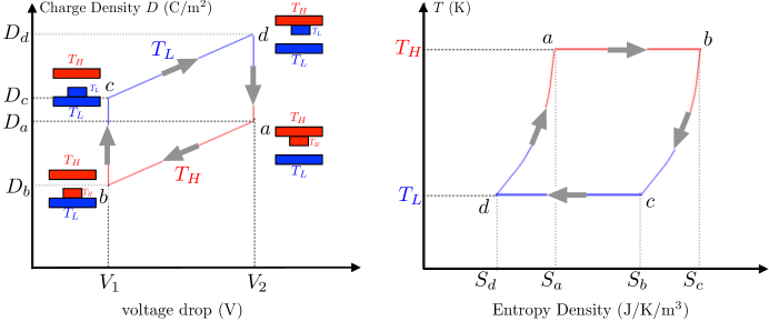
The four processes that make up the cycle are as follows. (1) Process is an isothermal process, where the pyroelectric element, of temperature that has just reached by receiving heat from the HTR (state ), is deflected by the bimetal cantilevers to state , where the pyroelectric element has just been brought in thermal contact with the LTR. During this process, the voltage drops from to . The voltage is controlled by a sensor as described in Ref. [1]. The heat gained by the pyroelectric element per unit volume during this isothermal process is , where is the thickness of the pyroelectric element. (2) Process is a constant voltage process during which heat is transferred from the pyroelectric element to the LTR. The heat lost per unit volume is , where is specific heat of the pyroelectric element. (3) Process is an isothermal process during which the pyroelectric element, at , is pulled back toward the HTR by the bimetallic cantilevers as they unbend due to cooling. The heat lost by the pyroelectric element per unit volume during this isothermal process is . (4) Process is a constant voltage during which heat is transferred from the HTR to the pyroelectric element. The heat gained per unit volume is . With , the net work produced per cycle is then
| (4) |
The power production is then the product of and the cycling frequency ,
| (5) |
The thermodynamic efficiency is
| (6) |
where the Carnot efficiency is and
| (7) |
Pyroelectric properties of high-quality (0001)AlN films grown on (111) Si were experimentally measured using the dynamic method in Ref. [19]. The reported value of the pyroelectric coefficient was in the range of 6-8 , over a temperature range of 15-35 . With at room temperature[20], the corresponding range of the figure-of-merit of 0.8-0.95. The pyroelectric coefficient studied in Ref. [19] was independent of temperature and applied bias. The specific heat of AlN is J/kg [21]. In Ref. [22], the reported range of values of the pyroelectric coefficient, measured experimentally at room temperature (), is 10 - 12 . Dependence of the relative permittivity on the temperature can be inferred from Ref. [23], where the variation of the capacitance with temperature was studied. Over a temperature range of , decreases with as °K-1. With , the pyroelectric coefficient, expressed in Eq. (1), may be approximated as , given that the electric field should not exceed the dielectric strength.
Upon inspecting Eqs. (4-7), we make the following observations. Assessing the efficiency of the pyroelectric device as a heat engine is dependent on the nature of the HTR as an energy source, given that the LTR is an infinite sink; i.e. it maintains its temperature. If the HTR is an infinite source, i.e. it maintains its temperature at all times as it exchanges heat with the pyroelectric element, then the frequency of operation is more important than how close the efficiency is to the Carnot efficiency. For given , , and pyroelectric material properties ( and ), the ratio of can be increased by increasing . AlN possesses a relatively high dielectric strength[21] of . This property allows applying large electric field difference in the Ericsson’s cycle leading to large voltage difference. For , , where . It can be observed from Eq. (6) that for (or ) and for (or ). For and , and . For given , , pyroelectric material properties ( and ), and , the power production (Eq. (5)) can be increased by increasing the operation frequency, , and the volume of the pyroelectric capacitor . Note that a smaller thickness of the capacitor implies that one needs to apply a smaller voltage across the capacitor, for given value of the . Another key aspect of assessing the performance is whether the power output should be reported per unit area of the device or per unit volume. Reporting the power density as the power output per unit volume may make more sense because it takes into account the distance between the HTR and the LTR. It is also more representative than the surface density when the devices are stacked. The power produced per unit volume is
| (8) |
Note that and are the maximum and minimum average temperature of the pyroelectric capacitor over a cycle.
4 The Reduced Order Model
Reduced order modeling[24] is an essential tool to make affordable the cost of computer-based design cycles. In the section, we present the reduced order model of the thermo-mechanical dynamic operation. The model also accounts for the damping forces imparted on the capacitor by the surrounding gas. The model is validated by comparing with detailed numerical simulations using Ansys, as presented in SectionmodelValidation. Being two orders of magnitude faster, the reduced order model is used to optimize the design over wide ranges of design parameters. To this end, the model is embedded within an optimization algorithm to estimate the dimensions that maximize the power produced per unit volume for a given temperature difference between the HTR and the LTR.
The motion of the pyroelectric capacitor, assumed to be rigid of mass and position , is governed by
| (9) |
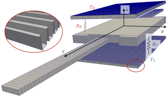
where is the thermo-mechanical force imparted by the bimetal cantilevers, is the torsion force imparted by the tethers, and is the damping force imparted by the surrounding gas. The thermo-mechanical force imparted by the bimetal cantilevers on the capacitor takes into account the deformation due to thermal expansion (contraction) caused by temperature changes. Next, we present models for calculating these forces along with the temperature distribution in the device. Numerical solution of the model equations require spatial discretization of the different elements, as depicted in Fig. 3.
4.1 Forces by the bimetal cantilever and the tethers
In this section, we present an expression for the force exerted by the bimetal cantilevers on the pyroelectric capacitor. We choose the tethers to be sufficiently compliant so that the horizontal force is small compared to the vertical force. This requires the bending stiffness of the tethers in the horizontal -direction to be small compared to the bending stiffness in the vertical direction -direction, i.e. . The distance between the tethers and the pyroelectric capacitor must be sufficiently large to provide the needed room for bending.
The vertical force exerted by the beams on the pyroelectric capacitor is a function of their temperatures and tip deflections. The (downward) force at the tip of the bimetal cantilevers is the sum of a linear spring component and a thermal expansion component
| (10) |
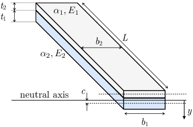
where is the tip deflection induced by thermal expansion. For a spatially uniform temperature distribution , where the curvature, , of the bimetal cantilever due to thermal expansion can be found in Ref.[25]
| (11) |
is the equivalent flexural rigidity and is the change in temperature of the bimetal cantilevers from a reference value, , for which . The various dimensions in Eq. (11) are depicted in Fig. 4. The equivalent flexural rigidity, , is
| (12) |
where , the location of the common neutral axis relative to the axis of the lower beam, is
| (13) |
Since the heat transfer in the bimetal cantilever is slow compared to that in the pyroelectric capacitor, the temperature distribution along the bimetal cantilever is non-uniform. In this case, the beam is discretized into a number elements each of which assumes a uniform temperature. The tip deflection, arising from thermal expansion, is obtained as
| (14) |
where the curvature of element calculated from Eq. (11).
Since the bimetal cantilever is connected to the plate through the tethers, it is necessary to factor in the impact of the tethers on the force at the tip of the bimetal cantilever. The contribution of the tethers to this force can be divided into two independent components: torsion and bending of the tethers. Torsion of the tethers occurs due to the bending of the bimetal cantilever while the pyroelectric plate stays horizontal (due to symmetry) as it shuttles back and forth between the two thermal reservoirs. At the same time, the tethers experience bending in the direction caused by the thermal expansion/contraction of the bimetal cantilever. Since the tethers are designed so that this bending compliance is large, we neglect the associated horizontal force component on the bimetal cantilever tip, as discussed at the beginning of this section. The tethers torque, , is transformed to a bending moment on the tip of the bimetal cantilever element. The equivalent vertical force at the tip of the bimetal cantilever that yields the same tip displacement as that due to the moment, assuming small deflections, is
| (15) |
where is the shear modulus, is the length the tether, is the angle of twist at the tip of the tether and (Ref. [26]).
4.2 Gas Damping
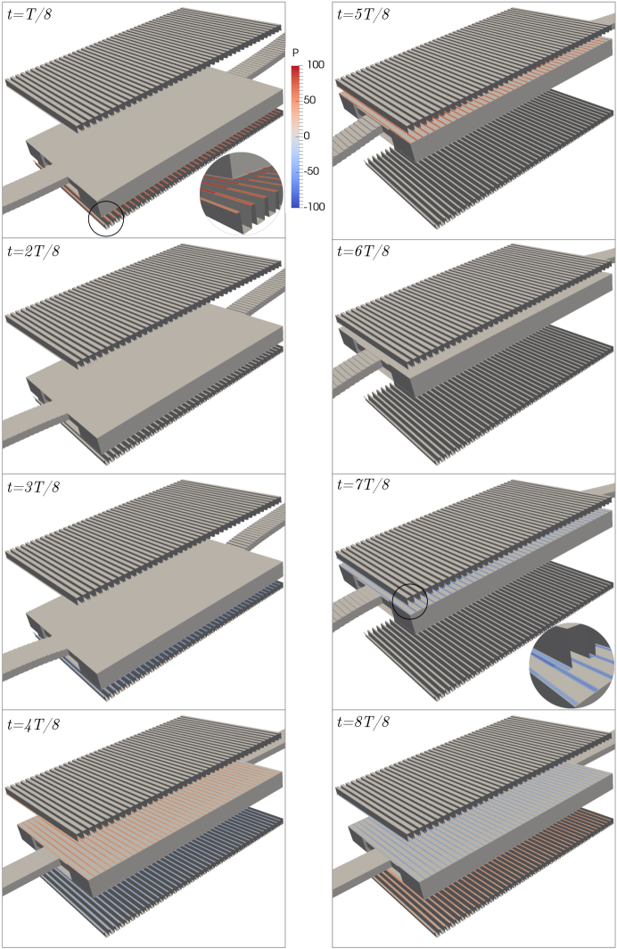
In order to realize the desired damping force for optimal performance of the device, the HTR and the LTR are patterned with trenches, as shown in Fig. 1. In arriving at the optimized designs presented in Section 8, the trench width and depth are adjusted so that the pyroelectric plate is sufficiently damped while maximizing the energy produced.
The motion of the pyroelectric capacitor is such that it remains parallel to the thermal reservoirs. In addition, the gap () separating the capacitor and each of the reservoirs is much smaller than the plate length () and width (). At an operation frequency of , the average plate speed is . The average speed at which the air is pushed as the plate squeezes the air film is then , where is the plate perimeter. The Reynolds number of the flow is , where is the kinematic viscosity of air at atmospheric conditions. Since , the flow can be modeled as inertia free. In addition, the flow is assumed to be isothermal. This assumption is justified on the grounds that viscous dissipation does not lead to any appreciable temperature rise and that, in non-insulated micro-devices, the heat generated will be lost quickly due to the large surface to volume ratio. The fact that the squeeze film thickness (the gap separating the pyroelectric plate from either reservoir) is much larger than the mean free path, , of air (at the thermodynamic state corresponding to the enclosure pressure and ambient temperature) implies that the flow is in the continuum regime, i.e. . The only exception is when the pyroelectric plate gets too close (a few mean free paths) to either reservoir. Under the assumptions of isothermal and inertia-free flow in the continuum regime, we can use the lubrication theory whereby the pressure, , of the air film between the pyroelectric plate and either reservoir is governed by the Reynolds equation
| (16) |
where is the gap separating the pyroelectric plate and the thermal reservoir (see Fig. LABEL:figure:pyroWithTrenches), and is the effective viscosity [27, 28], expressed as .
We assume that the change in pressure, , introduced by the motion of the pyroelectric capacitor is a small compared to the unperturbed enclosure pressure, . Then for , Eq. (16) is approximated as
| (17) |
The damping force acting on the plate is then computed by integrating, over the area of the pyroelectric capacitor area, the difference in pressure between the bottom and top surfaces
| (18) |
Since pyroelectric plate travels the entire distance separating the two reservoirs, solutions based on the linearized Reynolds equation[29] for small displacements are not applicable here. The nonlinear partial differential Eq. (17) is numerically solved in each of the two gas film domains between the capacitor and the two thermal reservoirs. The numerical method uses an explicit first order time integration scheme with second order finite difference discretization of the spatial derivatives. Figure 3 shows an example of the mesh used to represent the surface of the trenched thermal reservoirs when solving Eq. (17) .
Heat Transfer
The heat model is based on dividing the device into three different zones as depicted in Fig. 3: the pyroelectric plate, the tethers, and the bimetal cantilever. The model also takes into account the thermal resistance of the gas film between the capacitor and the thermal reservoirs. Each zone is modeled by the discretized 1D heat equation (along the dominant component of the heat flux) using second order central difference scheme for the diffusion term and first order explicit time integration scheme, as presented next for the capacitor. Similar discretizations were carried out for the tethers and bimetal cantilevers in the and directions respectively.
The pyroelectric capacitor temperature, , is assumed to be uniform in the () plane of the capacitor. Its variation along the direction is captured by discretizing the capacitor into layers in the plane, where the energy balance for layer of thickness is governed by
| (19) |
where . For the interior nodes, the rates of heat transfer into and out of the layer are
where , , refers to capacitor element in contact with tether with intersection area , is the Kronecker’s Delta, and the thermal resistance . For ,
and for ,
| (20) |
where and are the thermal resistances of the gas film between the capacitor and the high and low temperature reservoirs respectively. Referring to Fig. 1, these resistance are approximated as
| (21) | |||||
| (22) |
where is the fraction of the capacitor area that is exposed to trenches and .
5 Dynamic Operation
In this section, we investigate the dynamic behavior of the device using Ansys simulations. Understanding the dynamic operation of the device is essential for identifying the key design considerations which will in turn enable tightening the ranges of design parameters used in the design optimization procedure presented in Section 6 . The properties of the materials comprising the bimetal cantilever layers, tethers, and pyroelectric capacitor for all the designs considered in this work are presented in Table 1. Note that these materials are commonly used in MEMS devices [2]. To aid the discussion in this and the following section, we employ a device with dimensions listed in Table 2.
| cantilever | cantilever | Tethers | Pyroelectric | |
| Layer 1 | Layer 2 | capacitor | ||
| Material | Al | Si | Al | AlN |
| () | 2770 | 2330 | 2770 | 3260 |
| () | 875 | 712 | 875 | 740 |
| () | 150 | 148 | 150 | 140 |
| () | 71 | 190 | 71 | 350 |
| 0.33 | 0.22 | 0.33 | 0.24 | |
| bimetal cantilever | bimetal cantilever | Tethers | Pyroelectric | |
| Layer 1 | Layer 2 | Capacitor | ||
| Length | 1000 | 1000 | 20 | 1000 |
| Width | 20 | 20 | 2 | 140 |
| Height | 2.5 | 2.5 | 5 | 8 |
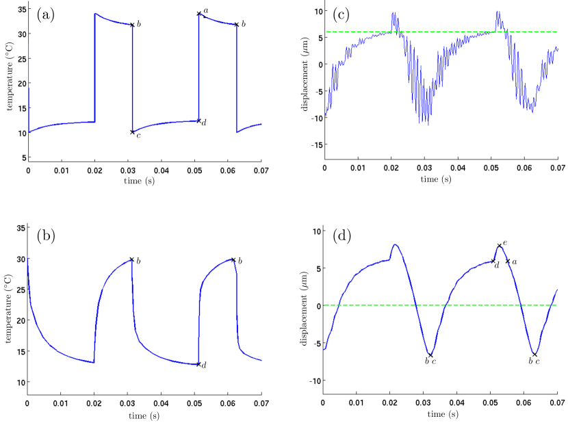
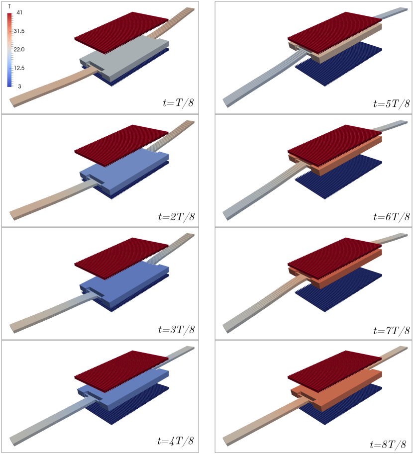
The gap separating the reservoirs and the temperature difference between the two reservoirs are selected to be and . For the Ansys simulations of the thermo-mechanical dynamical behavior, thermal contact with the reservoirs is modeled by setting the temperature of the pyroelectric capacitor to that of the reservoir during contact. The alternating temperature boundary conditions are assigned as a function of time depending on the state of contact with the reservoirs. As the capacitor travels between the two reservoirs, we assume that the heat losses to the surroundings are negligible. Every time step, the Ansys transient heat transfer solver computes the temperature variation within the device, as shown in Figs. 5(a) and (b) at two different locations. The temperature distribution is then imported by the transient structural solver which simulates the device motion and the bimetal cantilevers actuation as shown in Figs. 5(c) and (d).
5.1 Heat Transfer Dynamics
Figs. 5(a), 5(c) and 5(d) show the time evolution of the temperature and the displacement of the center of the capacitor. Fig. 5(b) shows the time evolution of the temperature at a point on the bimetal cantilever located at a distance of 200 from the capacitor. State corresponds to the time instant of contact between the capacitor and the LTR where the contacting capacitor surface is assigned the temperature of the LTR (). Upon contact, the capacitor cools rapidly () and reaches the temperature of the reservoir in almost . The speed of this heat transfer is in accordance with that predicted by the time scale analysis, Eq. (23). At state , the capacitor detaches from the reservoir as a result of the pull force induced by the cooling down of the bimetal cantilevers. Once it detaches, the capacitor starts absorbing heat from the bimetal cantilevers which explains the capacitor temperature increase over the period in Fig. 5(a) and the corresponding bimetal cantilevers temperature decrease in Fig. 5(b). At state , the capacitor contacts the HTR. The reservoir temperature then rises quickly () to that of the HTR. Once the temperature of the bimetal cantilevers increase sufficiently, the capacitor is pulled from the HTR (state in Fig. 5(d) ) and moves until it contacts the LTR at state . This completes the cycle.
5.2 Thermo-mechanical Behavior of the bimetal cantilever
In order to further understand the thermo-mechanical behavior of the bimetal cantilevers underpinning the actuation mechanism, simulations were carried out without imposing any mechanical boundary condition on the displacement of the capacitor at contact with the thermal reservoirs. Upon contact with the HTR at state (Fig. 5(d)), the elevation of the capacitor increases toward , indicating that the thermal inertia of the bimetal cantilevers and the capacitor kept pushing the capacitor through the HTR until state is reached, at which point the capacitor is pulled away from the HTR toward the LTR. This behavior, observed when the capacitor reaches the HTR, is a consequence of its rapid lateral thermal expansion as it receives heat from the reservoir. This deformation imparts a moment on the bimetal cantilevers that causes them to deflect upwards between points and (Fig. 5(d)). As heat continues to diffuse into the bimetal cantilevers, bending starts to take effect. Consequently, the bimetal cantilevers start deflecting downward once state is reached (Fig. 5(d)). In contrast, at the impact with the LTR, the lateral thermal contraction of the pyroelectric capacitor upon cooling imparts a moment that also deflects the bimetal cantilevers upward. This effect adds to the upward bending of the bimetal cantilevers as they lose heat to the capacitor. Hence, the capacitor does not fall below the LTR and the duration separating states and is small.
Another characteristic of the observed asymmetric behavior is that the capacitor takes more time to travel from the LTR to the HTR than from the HTR to the LTR. This behavior is attributed to the component of the vertical force that arises from expansion/contraction of the pyroelectric capacitor and the bimetal cantilevers. If the tethers are sufficiently stiff in the direction, then this force will add to the upward force during process and will oppose the downward force during process , as depicted in Fig. 5(d).
5.3 Natural Structural Oscillations and Damping
To observe the natural structural oscillations and the impact of damping, two simulations were carried out, one without damping (Fig. 5(c)) and one with damping (Fig. 5(d)). The two simulations exhibit oscillations between the reservoirs with the same operational frequency of about . The undamped response, shown in Fig. 5(c), exhibits high frequency oscillations about the damped response of Fig. 5(d). The frequency of these oscillations is about , which is within of the frequency () of the highest energy mode of vertical translational oscillations predicted by modal analysis. When a damping coefficient of is introduced, these high frequency structural oscillations disappear, as seen in Fig. 5(d).
5.4 Thermo-mechanical Dynamics of the Damped Constrained Oscillations
As discussed earlier, the bending stiffness of the tethers cause the operation cycle to be asymmetric, where the capacitor spends more time traveling from the LTR to the HTR than from the HTR to the LTR. The operation frequency in this case is . Increasing the operation frequency is a key design objective, since the power output is the product of the work produced per cycle (Eq. (4)) and the operation frequency. To increase the operating frequency, the design is modified so that the asymmetry between the durations and of Fig. 5(c) is significantly reduced. This is realized by increasing the bending compliance of the tethers by a factor of 10 without affecting the heat transfer dynamics through the tethers. This may be accomplished by reducing the tether width by a factor of and increasing its height by the same factor. Reducing the bending stiffness of the tethers will diminish the contribution of the thermal expansions/contractions of the capacitor/tethers to the vertical force on the capacitor. Instead, these expansions/contractions will contribute to tethers deflections.
In the simulation results presented next for the modified design, the contact between the pyroelectric capacitor and the thermal reservoirs is modeled by imposing the corresponding limits on the displacement of the capacitor. Figs. 7 and 8 show that, upon reducing the tether -bending compliance and placing stops at the locations of the LTR and the HTR reservoirs, the operation cycle is nearly symmetric with a frequency of 75 . Figures 9 and 10 show WHAT?
6 Design Considerations
100
In this section, we discuss design considerations based on the time scales characterizing heat transfer and structural dynamics. We also discuss the necessary conditions for sustained oscillation of the device, and answer the question of whether these sustained oscillations can take place at the mechanical resonance frequency. Based on the discussion, we present in Appendix B a simple design procedure that yields preliminary dimensions which serve as starting values for the optimization algorithm wrapped around the model presented in Section 4.
6.1 Heat Transfer Considerations
Crucial to sustained oscillations of the pyroelectric capacitor is designing for the relation between , the time it takes the capacitor to store internal energy by heat transfer from the HTR, and , the time it takes the bimetal cantilevers to pull the capacitor away for the reservoir. For sustained oscillations, the capacitor must store a sufficient amount of internal energy before it detaches from the HTR. After separation, the thermal energy stored in the capacitor continues to heat the bimetal cantilevers which, in turn, exert a force on the capacitor that pushes it toward the LTR. The energy stored in the capacitor must be such that the heat gained by the bimetal cantilevers is sufficient to push the capacitor all the way to the LTR. Similar arguments can be made for detachment from the LTR and subsequent travel to the HTR.
The time scale is estimated by relating the capacitor’s change in internal energy with the heat transferred by conduction through the thickness of the capacitor
| (23) |
where is thickness of the pyroelectric capacitor, and is the thermal diffusivity of the pyroelectric material.
In order for the capacitor to detach from the thermal reservoir, the force exerted by the bimetal cantilevers on the capacitor should switch its direction so that it pulls the capacitor away from the reservoir. How quickly this force reverse its direction depends on the change in the bimetal cantilevers temperature. In estimating , the time scale required for such a change to take place, we assume that the bimetal cantilevers force needed to detach the capacitor from the thermal reservoir develops over the time it takes the heat from the capacitor, flowing through the tethers, to diffuse along a fraction of the bimetal cantilever length, . The resulting change in average temperature of this portion (of length ) of the bimetal cantilever is . The time scale can then be estimated from the balance
where and are respectively the thermal resistances of the tethers and bimetal cantilevers of length . Note that introducing the tethers adds to the degrees of freedom so that we can adjust by changing , provided that and . The tethers may be thought of as thermal resistors that can be designed to regulate the flow of heat between the pyroelectric capacitor and the bimetal cantilevers.
Hence, in order to maintain the device’s oscillations the following condition should be satisfied:
| (24) |
For the materials listed in Table 1, . If is such that thermal resistance of the tethers is much less than that of the bimetal cantilevers of characterisitc length , then a necessary condition for the sustained cyclic operation of the device to be sustained is
| (25) |
Note that is primarily dependent on and on , the travel distance of the pyroelectric capacitor between the two reservoirs.
We point out when condition is satisfied, the time scale limiting the cycling frequency of the device is ; the time scale of thermal diffusion along the bimetal cantilever,
| (26) |
6.2 Structural Mechanics Considerations
As previously mentioned, structural mechanics considerations require the tethers to have a small torsional stiffness and a bending stiffness in the direction that is much smaller than that of the bimetal cantilever. This can be satisfied by choosing the tether width to be as small as possible and selecting its length and thickness such that , , and . In order for the pyroelectric capacitor to travel the entire distance separating the two reservoirs, the thermal expansion contribution to the force acting on the capacitor must be larger than the restoring elastic component. Referring to Eq. (10), the length of the bimetal cantilever must be chosen to be sufficiently large. Note however, that choosing to be too large results in reduction in the speed of the device. This is because (see Eq. (26)). The pyroelectric capacitor thickness, , must be sufficiently large so that it behaves as a rigid body. Dimensions of the pyroelectric capacitor should be carefully chosen as they also affect the thermal behavior (see Eq. (23)), the pyroelectric effect and the resulting power output (Eqs. (4-8)), and the damping force (Eq. (18)).
6.3 Operation at the Mechanical Resonance Frequency
Referring to Eq. (5), the power output is proportional to the frequency, volume of the pyroelectric capacitor, and the difference in temperature between the HTR and the LTR. Here we investigate the conditions of maximizing the frequency for given pyroelectric capacitor volume and material properties of the pyroelectric capacitor, tethers, and bimetal cantilever layers. We also answer the question whether the device can operate at the mechanical resonance frequency. Increasing the operation frequency can be accomplished by reducing the bimetal cantilever length (Eq. (26)), which in turn requires decreasing the tether’s length and pyorelectric capacitor thickness, as required by conditions (Eq. 25) and (Eq. 24). Due to the requirement of large bending compliance in the direction, we expect the tethers width to be the smallest dimension in the device. Thus, the minimum dimension allowed by the fabrication process puts an upper bound on the maximum operation frequency of the device. In addition, reducing the pyroelectric capacitor thickness while keeping its volume constant requires increasing its planar area proportionally, which increases the gas damping force. In order for the device to operate at the mechanical resonance frequency, we require where the resonance frequency is and the bending stiffness of a single bimetal cantilever is . Note that, by design, the contribution of the tethers to the stiffness is negligible. For the material properties listed in Table 1, and choosing and , the condition reduces to
| (27) |
where is the total thickness of the bimetal cantilever in , and and are respecively the volumes of the bimetal cantilever and the capacitor. It can then be shown that the resonance frequency, which in this case is the same as the operating frequency, is related to the length () of the bimetal cantilever as
| (28) |
In Appendix B, we present a design procedure to estimate the device dimensions so that it operates at the mechanical resonance frequency for a given and . This procedure, along with the design considerations discussed above, were used to explore and explain the qualitative dependence on of the bimetal cantilevers length (Fig. LABEL:fig:designLbfVSDT), operating frequency (which is equal to the mechanical resonance frequency) (Fig. LABEL:fig:designLbfVSDT), and the length of the pyroelectric capacitor (assumed to have a square shape) for different values of distance separating the two reservoirs (Fig. LABEL:fig:designLcVSDT) . These dependences for different values of the travel distance are also discussed and presented in Figs. LABEL:fig:designLbVSDTVARDMIN, LABEL:fig:designfVSDTVARDMIN and LABEL:fig:designLcVSDTVARDMIN.
We conclude by pointing that that the trends presented in Figs. LABEL:fig:designLbfVSDT - LABEL:fig:designLcVSDTVARDMIN are only qualitative since the design procedure is not based on the dynamic solution of Eq. (9). The procedure also does not include the tethers or the damping force, and as such, serves only to gain physical insight and to provide initial values of the geometrical parameters to be used in the optimization algorithm that incorporates a numerical solver of the reduced order dynamic model presented in Section 4. The optimization algorithm is used to arrive at device dimensions that maximize the output work, as discussed in Section 8.
7 Validation of the Model
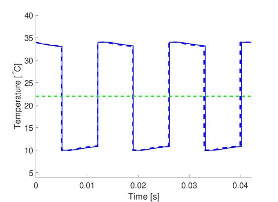
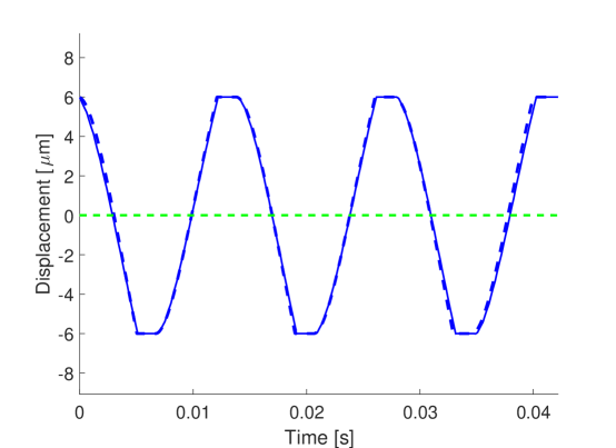
Validation of the reduced order model was carried out in three phases. In the first phase, the heat transfer and the bimetal cantilever tether force models were validated by comparing with Ansys simulations. Refer to Appendix A for details. In the second phase, validation of the coupled thermo-mechanical model was carried out by comparing with Ansys simulations the dynamic behavior of the device of dimensions listed in Table 2. Other conditions are stated at the end of Section 5. The comparison presented in Figs. 7 and 8 for the change with time of the capacitor temperature and displacement over three operation cycles at the quasi-stationary state shows that the reduced order model accurately predicts the dynamic behavior of the device.
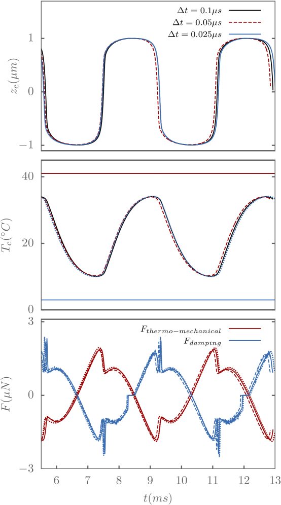
The third phase entails choosing the time step and spatial resolution used in the model as a tradeoff between accuracy and cost. Impact of the computational time step on the accuracy of the scheme is assessed for case 7 (Table 3) in terms of time evolution of the pyroelectric capacitor position, average temperature, and the damping and thermo-mechanical forces. As can be seen from Fig. 11, choosing yields a sufficiently accurate solution. Noting that for this case, the operating frequency is highest (291 from Fig. 14), we chose for all the other cases. As for the mesh size, choosing yielded a damping force that is nearly independent of the mesh size.
8 Optimal Designs
The simple design procedure presented in Appendix B serves to provide the dynamic solver with initial guesses of the various dimensions. The solver, which is based on the model presented in Section 4, simulates the thermo-mechanical dynamic operation, accounting for the heat transfer between the reservoirs, capacitor, and bimetal cantilevers, and for the thermo-mechanical, torsion and damping forces imparted on the capacitor respectively by the bimetal cantilevers, the tethers, and the surrounding fluid. Eq. (9) is numerically solved using a first order explicit time stepping scheme. Computing the damping force by integrating Eq. (18) requires solving Eq. (16). Being the most expensive step, numerical solution of Eq. (16) is carried out in parallel using OpenMP where the computational mesh is distributed among the CPU cores.
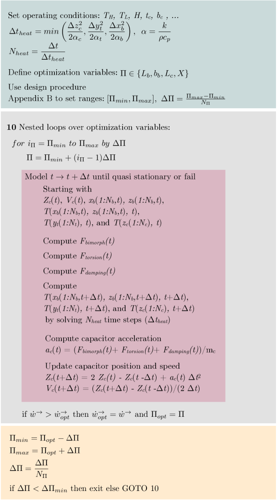
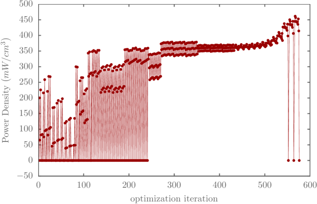
As shown in Fig. 12, the solver is embedded in an optimization algorithm that maximizes the work produced per unit volume (Eq. (8)) while meeting the various constraints imposed by the reduced order model. For example, all the optimal designs presented below satisfy the condition , which guarantees a sufficiently larger bending compliance (in the direction) of the tethers. The optimization algorithm employs a basic incremental search along all the design coordinates. Once an improved design is identified, the incremental search starting from the new improved design in repeated. The procedure continues until no further improvement is reached. We point out here that gradient-based optimization approaches did not offer any advantages due to the fact that the solution space is not only noncontinuous, but rather patchy. Nearly optimal designs were obtained using the optimization algorithm for different values of . The various dimensions of these designs are listed in Table 3.
| case # | ||||||||||||
|---|---|---|---|---|---|---|---|---|---|---|---|---|
| 1 | 35 | 9 | 20 | 2.5 | 0.2893 | 454 | 13 | 4.25 | 1880 | 4.25 | 0.75 | 15 |
| 2 | 36 | 8 | 20 | 2.5 | 0.3043 | 460 | 10 | 4.75 | 1880 | 5.75 | 0.75 | 15 |
| 3 | 37 | 7 | 20 | 2.5 | 0.2850 | 460 | 9 | 5 | 1840 | 5 | 1 | 20 |
| 4 | 38 | 6 | 20 | 2.5 | 0.3000 | 455 | 11 | 5 | 1880 | 5 | 1 | 20 |
| 5 | 39 | 5 | 18 | 2.5 | 0.3029 | 453.75 | 13 | 5 | 1880 | 5 | 1 | 20 |
| 6 | 40 | 4 | 16 | 2.5 | 0.2981 | 460 | 15 | 5 | 1880 | 5 | 1 | 20 |
| 7 | 41 | 3 | 14 | 2.25 | 0.2156 | 435 | 11 | 5 | 1900 | 5 | 1 | 20 |
Figure 13 shows HERE
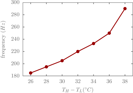
As shown in Fig. 14, the operation frequency increases with temperature difference between the two reservoirs, in accordance with the discussion in Section 6. The operation frequency ranges from 183 for to 291 for .
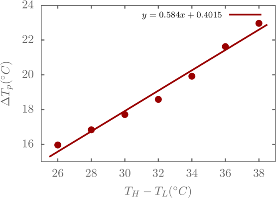
Since the pyroelectric capacitor does not get in contact with either reservoir but rather reaches within a distance of , we expect that, , the peak to peak change in the average capacitor temperature over a cycle to be less than . The plot presented in Fig. 15 show that increases linearly with , with the ratio being nearly a constant of 0.6.
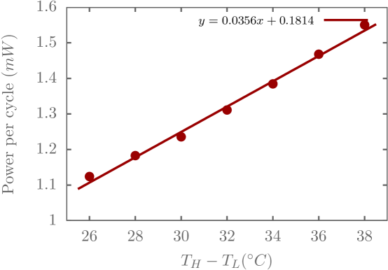
The power produced per cycle, , is plotted against in Fig. 16. It follow a linear trend similar to , which follows from Eq. (8).
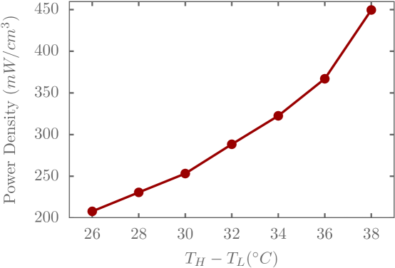
The power density per unit volume, expressed in Eq. (8), increases quadratically in , as seen in the plot of Fig. 17. As increases from 26 to , the power density increases from to .
We finally note that, for the considered range of , the power generated per unit surface area ranges from 0.4 to 0.65 , as presented in Fig. LABEL:fig:powerPerAreaVSDT of Appendix C. These values are compared with power density values of energy harvested from other environmental sources in Table 4.
| Energy source | Method | Characteristics | Harvested Power | Efficiency |
| Density () | ||||
| Light | Photovoltaic | Outdoor | 10 | 5-30 % |
| Indoor | 0.01 | |||
| Ambient air flow | Microturbines | 1 | ||
| Mechanical vibration | Piezoelectricity | machine () | 0.1-0.8 | 1-10 % |
| human () | ||||
| Mechanical vibration | Electromagnetic | machine () | 2 | |
| human () | ||||
| Thermal | Thermoelectric | machine | 1-10 | 0.15 - 10 % |
| human | ||||
| Thermal | Pyroelectric | = 26-38 °C | 0.4 - 0.65 | 5.4-6.74% |
| (This work) | ||||
| RF | Electromagnetic | background | (0.001-0.1) | |
| directed | 1 | 33 % |
Next, we investigate impact of , the separation between the HTR and the LTR. The temperatures of the HTR and the LTR are kept at and respectively. The thickness of the pyroelectric capacitor is selected to be . Other dimensions are listed in Table 5.
| case # | |||||||||||
|---|---|---|---|---|---|---|---|---|---|---|---|
| 1 | 15 | 3.5 | 0.305 | 480 | 10 | 5 | 1880 | 13 | 5 | 1 | 20 |
| 2 | 16 | 3.5 | 0.305 | 475 | 10 | 5 | 1880 | 14 | 5 | 1 | 20 |
| 3 | 17 | 3 | 0.305 | 470 | 10 | 5 | 1880 | 15 | 5 | 1 | 20 |
| 4 | 18 | 2.75 | 0.300 | 465 | 9 | 5 | 1840 | 16 | 5 | 1 | 20 |
| 5 | 19 | 2.75 | 0.300 | 465 | 9 | 5 | 1800 | 17 | 5 | 1 | 20 |
| 6 | 20 | 2.5 | 0.285 | 460 | 9 | 5 | 1840 | 18 | 5 | 1 | 20 |
| 7 | 21 | 2.5 | 0.305 | 460 | 9 | 5 | 1880 | 19 | 5 | 1 | 20 |
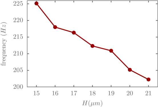
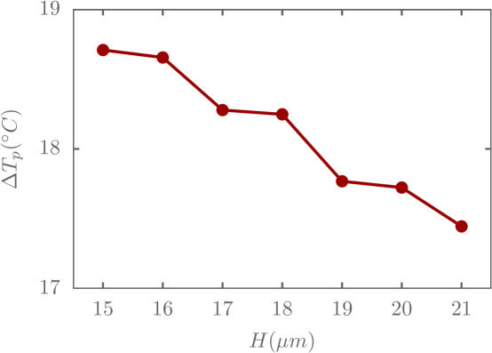
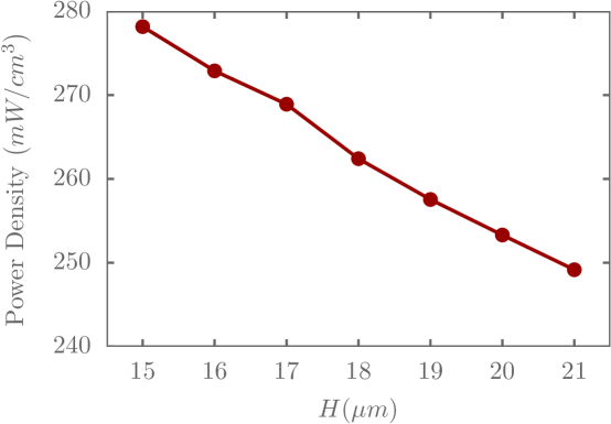
Fig. 18 shows that as increases, the operating frequency decreases. This decrease is, however, small because the gap separating the capacitor from either reservoir is kept constant by adjusting the capacitor thickness according to . As such, the distance traveled per cycle is the same for all cases and the slight change in frequency is attributed to the combined effect of a thicker capacitor and shorter bimetallic beams. As increases from 15 to 21 , the peak to peak change in the average capacitor temperature over a cycle decrease by 1.2 , according to Fig. 19. Since both and decrease as is increased, the power generated per unit volume decreases by , as shown in Fig. 20.
9 Conclusion
In this study, a new design of a MEMS pyroelectric energy harvester is proposed. During cyclic operation of the device, the pyroelectric capacitor plate remains parallel to the thermal reservoirs, which not only increases the rate of heat transfer across the gap, but also ensures nearly uniform temperature within the capacitor. This operation is enabled by the use of tethers of low torsional stiffness to connect the bimetal cantilevers to the plate. Investigation of various times scales key to thermo-mechanical operation of the device uncovered the conditions for self-sustained oscillations, and the conditions for these oscillations to take place at the mechanical resonance frequency (in the absence of gas damping). The physically-based reduced order model was employed to identify the length of the bimetal cantilever beams as a key design parameter. When embedded within an optimization algorithm, the model was used to arrive at device dimensions for nearly optimal power generation while operating in the self-sustained oscillations/contact-free operation regime. As the temperature difference between the two reservoirs increases from 26 to 38 , the power density harvested increased from 0.4 to 0.65 .
The proposed design along with the design methodology presented fill a gap in the under-explored area of MEMS pyroelectric energy harvesters, which brings us one step closer to realization of these devices.
Acknowledgments
This work was supported by the Munib and Angela Masri Institute of Energy and Natural Resources, Award Number 103352. The authors would like to thank Prof. Daniel Tartakovsky for his insightful comments.
References
- [1] Hunter S R, Lavrik N V, Bannuru T, Mostafa S, Rajic S and Datskos P G 2011 Development of mems based pyroelectric thermal energy harvesters SPIE Defense, Security, and Sensing (International Society for Optics and Photonics) pp 80350V–80350V
- [2] Hunter S R, Lavrik N V, Mostafa S, Rajic S and Datskos P G 2012 Review of pyroelectric thermal energy harvesting and new mems-based resonant energy conversion techniques SPIE Defense, Security, and Sensing (International Society for Optics and Photonics) pp 83770D–83770D
- [3] Bowen C R, Taylor J, LeBoulbar E, Zabek D, Chauhan A and Vaish R 2014 Energy & Environmental Science 7 3836–3856
- [4] Pandya S, Wilbur J, Kim J, Gao R, Dasgupta A, Dames C and Martin L W 2018 Nature materials 17 432
- [5] Fang J, Frederich H and Pilon L 2010 Journal of Heat Transfer 132 092701
- [6] Yang Y, Guo W, Pradel K C, Zhu G, Zhou Y, Zhang Y, Hu Y, Lin L and Wang Z L 2012 Nano letters 12 2833–2838
- [7] Lulec S Z, Adiyan U, Yaralioglu G G, Leblebici Y and Urey H 2016 Sensors and Actuators A: Physical 237 147–154
- [8] Lavrik N V, Sepaniak M J and Datskos P G 2004 Review of scientific instruments 75 2229–2253
- [9] Arlett J, Myers E and Roukes M 2011 Nature nanotechnology 6 203
- [10] Muriuki M G, Clark W W, Chen Q M and Wang Q M 2003 Design and analysis of a piezoelectric cantilever beam resonator Smart Structures and Materials 2003: Smart Electronics, MEMS, BioMEMS, and Nanotechnology vol 5055 (International Society for Optics and Photonics) pp 36–48
- [11] Puchades I and Fuller L F 2011 Journal of Microelectromechanical Systems 20 601–608
- [12] Nayfeh A H and Younis M I 2003 Journal of Micromechanics and Microengineering 14 170
- [13] Walraven J A 2003 Failure mechanisms in mems null (IEEE) p 828
- [14] Van Spengen W M 2003 Microelectronics Reliability 43 1049–1060
- [15] Patton S and Zabinski J 2002 Tribology International 35 373–379
- [16] Neil Mathur R S 2007 Teaching and Learning Packages (University of Cambridge) URL http://www.doitpoms.ac.uk/tlplib/piezoelectrics/index.php
- [17] Neil Mathur R S 2007 Teaching and Learning Packages (University of Cambridge) URL http://www.doitpoms.ac.uk/tlplib/pyroelectricity/credits.php
- [18] Whatmore R 1986 Reports on progress in physics 49 1335
- [19] Fuflyigin V, Salley E, Osinsky A and Norris P 2000 Applied Physics Letters 77 3075–3077
- [20] Akasaki I and Hashimoto M 1967 Solid State Communications 5 851–853
- [21] Accuratus 2013 Aluminum nitride, ain ceramic properties URL http://accuratus.com/alumni.html
- [22] Stan G, Botea M, Boni G, Pintilie I and Pintilie L 2015 Applied Surface Science 353 1195–1202
- [23] Engelmark F, Westlinder J, Iriarte G F, Katardjiev I V and Olsson J 2003 IEEE Transactions on Electron Devices 50 1214–1219
- [24] Issa L and Lakkis I 2014 Journal of Fluids Engineering 136 051201–051201–9 URL http://dx.doi.org/10.1115/1.4026199
- [25] Chu W H, Mehregany M and Mullen R L 1993 Journal of Micromechanics and Microengineering 3 4
- [26] Young W C and Budynas R G 2002 Roark’s formulas for stress and strain vol 7 (McGraw-Hill New York)
- [27] Veijola T 2002 Proceedings Modeling and Simulation of Microsystems 104–107
- [28] Veijola T, Kuisma H, Lahdenperä J and Ryhänen T 1995 Sensors and Actuators A: Physical 48 239–248
- [29] Blech J 1983 Journal of lubrication technology 105 615–620
- [30] Rasheduzzaman M, Pillai P B, Mendoza A N C and Souza M M D 2016 2016 10th International Symposium on Communication Systems, Networks and Digital Signal Processing (CSNDSP) 1–6
- [31] Vullers R, van Schaijk R, Doms I, Hoof C V and Mertens R 2009 Solid-State Electronics 53 684 – 693 ISSN 0038-1101 papers Selected from the 38th European Solid-State Device Research Conference – ESSDERC’08 URL http://www.sciencedirect.com/science/article/pii/S0038110109000720
- [32] Paradiso J A and Starner T 2005 IEEE Pervasive Computing 4 18–27 ISSN 1536-1268